

ProductPRODUCT
Featured products
Contact Us
- GE
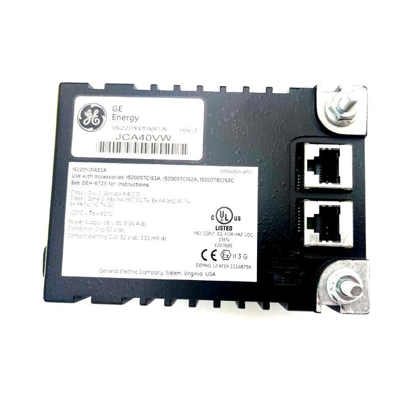
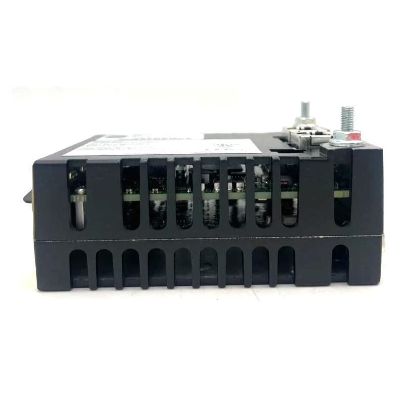
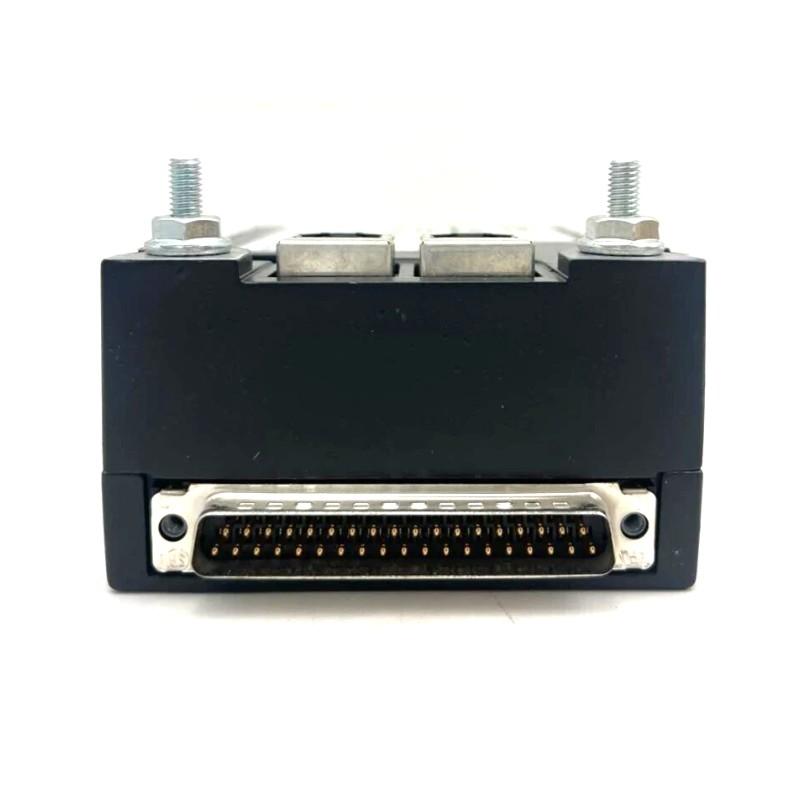
- IS220YDOAS1AJ
- Discrete Contact Input I/O Module
- USA
- 138 x 86 x 56 mm
- 0.907 kg
- Xiamen, China
- New & In Stock
- T/T, PayPal, Western Union
- 1 Year
- 1-3 Working Days
- DHL, UPS, TNT, FedEx and EMS.
- 24-Hour Service
- COO
- 5
Our advantage

Global Logistics
We have a 10-year logistics and express cooperation agreement, so our products can be shipped to any place in the world.

Brand new and original
Our products are imported in bulk from the place of origin. Because of the cooperative relationship, our products are all original and 100% new.

24-hour service
We provide 7*24 hours service to our customers. We will be there whenever you need us.

Price advantage
All our products are priced very favorably because we have our own warehouse and supply.
| Company Information | |||
| [email protected] | |||
| Mobile | +8615980777398 | ||
| +8615980777398 | |||
| 15980777398 |
Product Overview
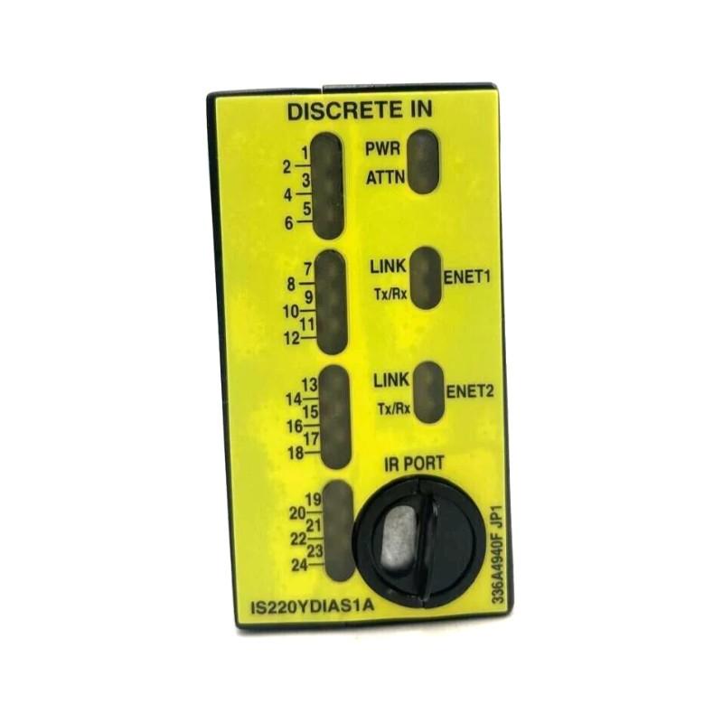
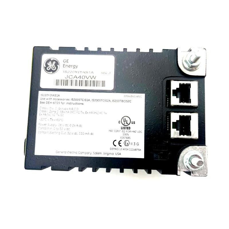
The GE IS220YDOAS1AJ Discrete Contact Input I/O Module is an industrial control component intended for integration into compatible automation systems that require discrete field-signal interfaces. Discrete contact signals are commonly used to represent equipment states, switch positions, relay conditions, and other binary operating information.
In industrial automation, contact inputs allow a controller to determine whether a field device is in an active or inactive state. This information can be used in programmed sequences, equipment-status monitoring, permissive checks, and alarm logic. When incorporated into a suitable control architecture, discrete I/O interfaces help connect field-level electrical conditions with automated process decisions.
The GE IS220YDOAS1AJ has specified dimensions of 138 × 86 × 56 mm and a listed weight of 0.907 kg. These values are useful for cabinet-layout planning, installation preparation, handling, and replacement assessment.
The exact electrical characteristics, input-channel arrangement, contact-sensing requirements, supported signal levels, terminal assignments, and I/O functionality must be confirmed against the specific hardware revision and host-system configuration before installation.
Technical Specifications
| Parameter | Specification |
|---|---|
| Manufacturer | General Electric (GE) |
| Model | IS220YDOAS1AJ |
| Product Type | Discrete Contact Input I/O Module |
| Product Family | GE IS220 Series |
| Primary Function | Discrete contact signal interfacing |
| Signal Category | Discrete / binary signals |
| Dimensions | 138 × 86 × 56 mm |
| Weight | 0.907 kg |
| Installation | Compatible industrial control equipment |
| System Role | Field-contact signal interface |
| Typical Applications | Equipment-status monitoring, contact-state acquisition, control sequencing, alarms, and industrial automation |
Note: Exact channel counts, electrical ratings, supported input arrangements, and terminal assignments should be verified for the installed module.
Understanding the GE IS220YDOAS1AJ
The GE IS220YDOAS1AJ is identified as a discrete contact input I/O module. In a typical automation environment, contact-based signals originate from devices such as auxiliary contacts, selector switches, limit switches, pushbuttons, and relay contacts.
These devices provide information about physical or electrical conditions. The control system receives the corresponding status through an appropriate input interface and evaluates it against the configured control logic.
A simplified signal path is:
Field Contact → Input Interface → Control System → Programmed Logic → Machine Response
For example, an auxiliary contact may indicate that a motor starter has changed state. The controller can use this information to update equipment status, confirm a sequence step, or identify a discrepancy between a command and the reported condition.
The actual capabilities and wiring arrangement of the IS220YDOAS1AJ depend on its specific configuration and compatible host equipment.
Discrete Contact Input Operating Principle
A discrete contact circuit represents a condition through distinct electrical states. Depending on the field device and circuit design, a contact may be open or closed, and the associated interface detects the resulting electrical condition.
A typical operating sequence includes:
- A field device changes contact state.
- The electrical condition reaches the input interface.
- The interface detects the applicable input state.
- The controller receives or reads the status.
- Programmed logic evaluates the signal.
- The system updates equipment status or initiates an appropriate response.
The contact state alone does not always establish whether equipment is safe or operational. Correct interpretation depends on the circuit design, configured logic, and intended behavior of the field device.
Role in Industrial Control Systems
Discrete contact inputs provide a connection between field-device conditions and controller logic. They allow an automation system to monitor equipment without relying exclusively on operator observation.
Common applications include:
- Monitoring motor or drive auxiliary contacts
- Detecting limit-switch activation
- Reading selector-switch positions
- Monitoring relay contact states
- Confirming equipment-ready conditions
- Tracking machine sequence steps
- Generating alarms from discrete status changes
- Supporting control permissives and interlocks
The module’s actual role should be established from the host-system design rather than inferred solely from its product name.
Industrial Applications
Motor and Drive Status Monitoring
Auxiliary contacts can report whether associated equipment has reached a particular electrical state. A controller can compare this feedback with the issued command to identify discrepancies.
Machine Position Detection
Limit switches and position contacts can provide discrete indications that a moving mechanism has reached a defined point.
Automated Assembly
Assembly machines may use contact-based signals to confirm fixture positions, guard conditions, and completion of individual sequence steps.
Material Handling
Conveyor and transfer systems can use discrete status signals to monitor position switches, equipment states, and selected operating conditions.
Process Equipment
Industrial process systems may monitor relay contacts, valve-position contacts, and other discrete signals as part of equipment supervision.
Alarm and Event Monitoring
Contact-state changes can be used to trigger alarms or record operating events when the control logic and monitoring system are configured accordingly.
Safety-related applications require appropriately rated and validated safety equipment. A conventional contact-input interface should not be assumed to provide a certified safety function unless that capability is explicitly confirmed.
Contact Signal Acquisition and Logic Processing
A contact input becomes useful when its physical state is interpreted correctly by the control system.
For example, a machine may require a guard-status contact to be in the expected state before a cycle can begin. The controller evaluates the input together with other permissive conditions before allowing the sequence to proceed.
A typical logic structure may include:
Input State → Validity Check → Sequence Condition → Control Decision
The program may also compare an expected contact state with a command or another feedback signal. If the expected transition does not occur within a defined interval, the system may generate a diagnostic message or alarm.
These behaviors depend on the controller program and should not be treated as built-in functions of the input module itself.
Installation and System Integration
Correct installation helps ensure that contact states are detected consistently and that the module operates within its intended system configuration.
Verify the Model Number
Confirm the complete identification:
GE IS220YDOAS1AJ
Check the hardware revision and intended installation position before installing or replacing the module.
Inspect the Module
Examine the housing, connectors, and accessible interfaces for signs of damage, corrosion, contamination, or deformation.
Confirm Host-System Compatibility
Verify that the module is supported by the installed control hardware, interface arrangement, and configuration.
Review the Wiring Diagram
Identify the correct terminals, signal references, and contact-circuit requirements from the documentation applicable to the exact module.
Secure the Installation
Follow the mounting requirements of the host equipment. Provide sufficient clearance for wiring, inspection, and replacement.
Check the Complete Signal Path
Before returning the system to service, verify the field contact, wiring, input interface, controller status, and associated logic.
Wiring and Electrical Considerations
Contact inputs may be used with different circuit arrangements. The correct wiring depends on the supported input design, external electrical conditions, and requirements of the host system.
Before connecting field circuits, confirm:
- Supported contact-input arrangement
- Required external signal or sensing supply, if applicable
- Electrical limits
- Common or reference connections
- Terminal assignments
- Field-device contact ratings
- Cable routing requirements
- Grounding and shielding practices, where applicable
Do not assume that a contact can be connected directly to any voltage source. Applying an incompatible voltage or wiring arrangement may damage equipment or cause incorrect input states.
Use suitable test instruments and approved procedures when checking live circuits.
Commissioning Procedure
A structured commissioning process can help identify wiring and configuration problems before normal operation.
Step 1: Confirm identification. Verify the model number and hardware revision.
Step 2: Inspect installation. Check mounting, connectors, and wiring.
Step 3: Verify electrical compatibility. Confirm that the field circuits match the module’s documented requirements.
Step 4: Operate the field contact. Change the contact state using an approved test procedure.
Step 5: Observe the reported input. Compare the physical contact state with the status available in the control system.
Step 6: Check the control logic. Confirm that the controller interprets the signal as intended.
Step 7: Test alarms and sequences. Verify the programmed response under controlled conditions.
Step 8: Record results. Document the final wiring, configuration, and any corrective work.
Where contact states are associated with moving machinery or hazardous processes, testing must follow the site’s approved isolation and commissioning procedures.
Troubleshooting the GE IS220YDOAS1AJ
Input problems can originate from the field contact, wiring, electrical reference, module interface, controller configuration, or application logic. Diagnosing these elements separately helps prevent unnecessary replacement.
Contact Changes but Input Status Does Not
Possible causes include:
- Defective or incorrectly operated field contact
- Open or damaged wiring
- Incorrect terminal connection
- Incompatible electrical conditions
- Missing or incorrect circuit reference
- Loose connector
- Configuration or interface problem
Check the contact and electrical signal using the documented circuit requirements before concluding that the module has failed.
Input Remains Permanently Active
Potential causes include a contact that remains closed, a wiring short, an incorrect reference connection, or a problem within the input circuit.
Compare the physical contact condition with the electrical signal and the state reported by the controller.
Input Remains Permanently Inactive
Possible causes include an open contact circuit, broken conductor, incorrect wiring, an inactive field device, or an incompatible signal condition.
Trace the signal path from the field device to the control-system indication.
Intermittent Input State
Intermittent behavior may result from:
- Loose terminals
- Worn contact surfaces
- Damaged cables
- Vibration
- Electrical interference
- Moisture or contamination
- Unstable electrical references
Inspect the field device and wiring under controlled conditions while observing the reported input state.
Several Inputs Become Abnormal
If multiple signals fail together, investigate shared wiring, common references, external supplies, connectors, interface connections, and host-system diagnostics. A simultaneous problem across several signals may indicate a common cause rather than multiple independent field-device failures.
Preventive Maintenance
Routine maintenance should focus on the complete contact-signal circuit.
Inspect Field Contacts
Check switches, relays, and auxiliary contacts for mechanical wear, unreliable operation, or damage according to the field device’s maintenance requirements.
Check Wiring
Inspect conductors for damaged insulation, loose terminals, abrasion, and signs of moisture ingress.
Inspect Connectors
Ensure that connectors are secure and free from visible damage or contamination.
Review Input Trends and Diagnostics
Where the control system provides suitable diagnostic information, investigate recurring or intermittent input faults.
Verify Circuit Identification
Maintain accurate labels and wiring records so that future troubleshooting does not depend on assumptions about terminal assignments.
Maintain Environmental Conditions
Protect the control equipment from excessive dust, moisture, vibration, and temperatures outside the applicable equipment limits.
Replacement and Compatibility Considerations
When replacing the GE IS220YDOAS1AJ, verify the complete model designation and relevant revision information.
Important checks include:
- Exact part number
- Hardware revision
- Host-system compatibility
- Connector configuration
- Contact-input electrical requirements
- Terminal arrangement
- Field wiring
- Configuration requirements
- Installation position
The specified dimensions are 138 × 86 × 56 mm, and the listed weight is 0.907 kg.
Physical similarity alone does not establish functional interchangeability. Before substituting another module, confirm that its electrical characteristics and system interfaces meet the requirements of the existing installation.
Physical Dimensions and Cabinet Planning
The listed dimensions of 138 × 86 × 56 mm provide a reference for cabinet layout and mechanical installation planning.
Engineers should consider:
- Mounting arrangement
- Connector accessibility
- Cable-entry direction
- Wiring bend radius
- Space for maintenance
- Separation from sources of electrical interference
- Access for inspection and replacement
The listed weight of 0.907 kg is useful for handling and installation preparation. The mounting arrangement should be assessed as part of the complete control assembly.
Integration with HMI and Supervisory Systems
When connected to a compatible controller and properly configured, discrete contact states can be presented on operator interfaces or supervisory systems.
Depending on the application, displayed information may include:
- Equipment running or stopped status
- Switch and limit-position states
- Machine-ready conditions
- Sequence progress
- Fault indications
- Interlock status
- Alarm and event information
Accurate display depends on correct field wiring, input mapping, controller logic, and HMI configuration. The input module itself does not determine how signals are presented to operators.
Key Advantages
- Discrete contact interfacing: Supports the acquisition of binary field-device states in a compatible control architecture.
- Automation integration: Input information can be used by control logic for equipment monitoring and sequence management.
- Status visibility: Contact states can support operator displays and alarm processing when properly configured.
- Maintenance support: Systematic input diagnostics help distinguish field-device faults from wiring or interface problems.
- Defined physical characteristics: Dimensions of 138 × 86 × 56 mm and a listed weight of 0.907 kg support installation planning.
- Replacement planning: The complete model designation provides a basis for checking compatibility with the existing system.
Technical FAQs
What is the GE IS220YDOAS1AJ?
The GE IS220YDOAS1AJ is identified as a Discrete Contact Input I/O Module for use in compatible industrial control systems.
What are the dimensions of the IS220YDOAS1AJ?
The listed dimensions are 138 × 86 × 56 mm.
How much does the module weigh?
The listed weight is 0.907 kg.
What is a discrete contact input used for?
A discrete contact input allows a control system to monitor binary conditions represented by field contacts, such as switch positions, auxiliary contacts, and equipment-status signals.
What causes a contact input to remain inactive?
Potential causes include an open circuit, damaged wiring, an inactive field device, incorrect terminal connections, incompatible electrical conditions, or an interface problem.
Can another GE module replace the IS220YDOAS1AJ?
A different module should not be assumed to be interchangeable. Confirm the complete part number, revision, electrical requirements, connector arrangement, and host-system compatibility before replacement.
What should be checked before wiring?
Verify the supported contact arrangement, electrical limits, terminal assignments, reference connections, and field-device requirements using the documentation for the exact hardware.
How can intermittent contact-input faults be diagnosed?
Inspect the field contact, wiring, terminals, electrical reference, and connectors while monitoring the input state. Check shared circuit conditions if multiple signals are affected.
Conclusion
The GE IS220YDOAS1AJ Discrete Contact Input I/O Module is intended for industrial control applications that require discrete contact-state information to be incorporated into an automation system. Such signals can support equipment-status monitoring, machine sequencing, alarm logic, and operating-condition checks.
With listed dimensions of 138 × 86 × 56 mm and a weight of 0.907 kg, the module’s physical specifications are useful for installation preparation, cabinet planning, and replacement logistics.
Reliable operation depends on correct field-device wiring, compatible electrical conditions, appropriate system configuration, and accurate control logic. Before installation or replacement, verify the complete GE IS220YDOAS1AJ model designation and confirm its electrical and functional compatibility with the intended host system.