

ProductPRODUCT
Featured products
Contact Us
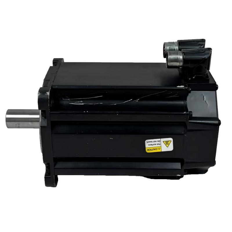
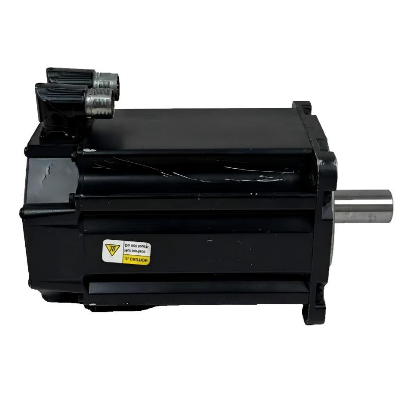
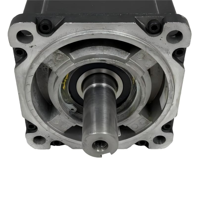
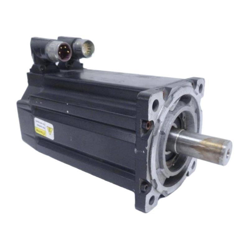
- Allen Bradley
- MPL-B520K-MJ74AA
- Low-Inertia Brushless Servo Motors Product
- USA
- 138 mm × 87 mm × 105 mm
- 13.9kg
- Xiamen, China
- New & In Stock
- T/T, PayPal, Western Union
- 1 Year
- 1-3 Working Days
- DHL, UPS, TNT, FedEx and EMS.
- 24-Hour Service
- COO
- 12
Our advantage

Global Logistics
We have a 10-year logistics and express cooperation agreement, so our products can be shipped to any place in the world.

Brand new and original
Our products are imported in bulk from the place of origin. Because of the cooperative relationship, our products are all original and 100% new.

24-hour service
We provide 7*24 hours service to our customers. We will be there whenever you need us.

Price advantage
All our products are priced very favorably because we have our own warehouse and supply.
| Company Information | |||
| [email protected] | |||
| Mobile | +8615980777398 | ||
| +8615980777398 | |||
| 15980777398 |
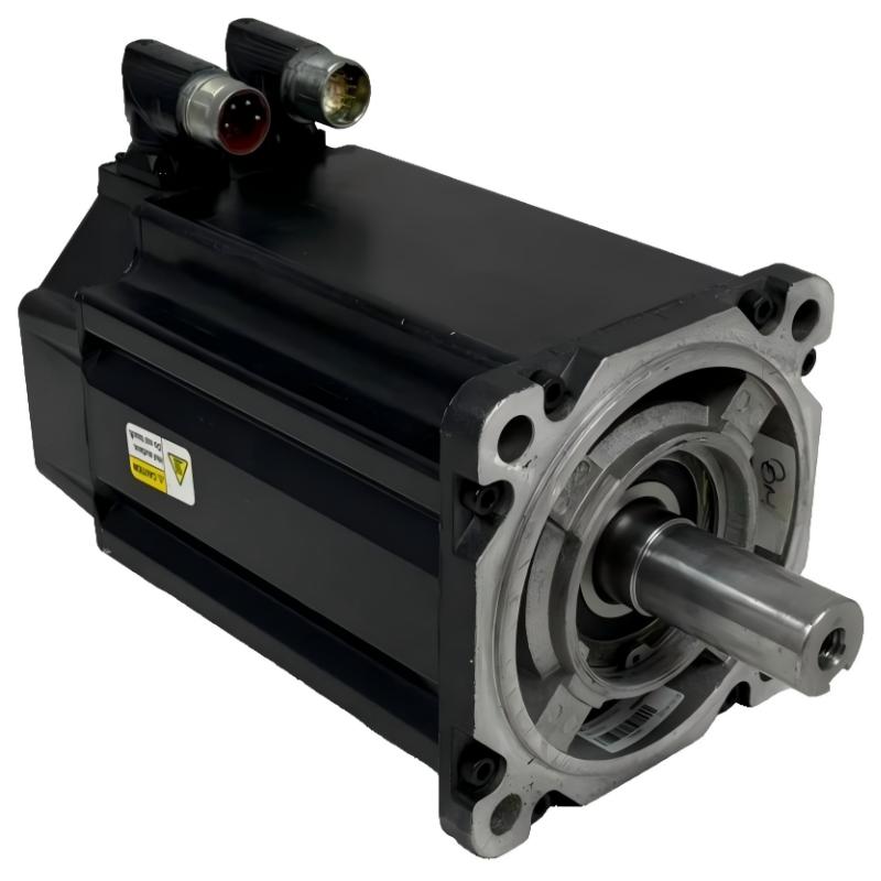
Allen-Bradley MPL-B520K-MJ74AA Servo Motor – Technical Specifications, Product Introduction, Applications, Advantages and Model Selection Guide
1. Product Overview
The MPL-B520K-MJ74AA is a low-inertia brushless AC rotary servo motor in the Allen-Bradley MP-Series MPL family.
It is a 460 V class, 4000 rpm, 3.5 kW-class servo motor with a multi-turn high-resolution absolute encoder, keyed shaft, SpeedTEC DIN connector, and integral 24 V DC holding brake.
The motor uses a 165 mm frame and a 50.8 mm magnetic stack. Its continuous stall torque is approximately 10.7 N·m, while its peak torque is approximately 23.2 N·m. The rated continuous output power is approximately 3.5 kW.
The combination of high operating speed, low rotor inertia, multi-turn feedback, and integrated brake makes this motor suitable for industrial machinery requiring accurate positioning, rapid acceleration and deceleration, and mechanical holding capability.
The 24 V DC brake is one of the most important differences between this model and the no-brake MPL-B520K-MJ72AA. The brake makes the MJ74AA configuration more suitable for applications where the motor axis must be held when servo torque is removed.
The motor uses a conventional keyed shaft extension, allowing it to interface with a wide range of couplings, gearboxes, pulleys, screw drives, rollers, and other industrial transmission components.
The right-angle SpeedTEC DIN connector is rotatable approximately 180°, providing additional flexibility when routing motor cables inside compact machinery.
2. Brand and Product Series
| Item | Specification |
|---|---|
| Brand | Allen-Bradley |
| Product Family | MP-Series |
| Product Series | MPL Low-Inertia Brushless Servo Motors |
| Product Type | Rotary servo motor |
| Model | MPL-B520K-MJ74AA |
| Voltage Class | 460 V AC |
| Motor Type | Low-inertia brushless AC servo motor |
| Frame Size | 165 mm |
| Magnetic Stack | 50.8 mm |
| Rated Speed | 4000 rpm |
| Continuous Torque | Approx. 10.7 N·m |
| Peak Torque | Approx. 23.2 N·m |
| Rated Output | Approx. 3.5 kW |
| Feedback | Multi-turn high-resolution absolute encoder |
| Shaft | Keyed shaft extension |
| Brake | 24 V DC integral holding brake |
| Connector | SpeedTEC DIN, right-angle |
| Connector Rotation | Approx. 180° |
| Mounting | IEC metric |
| Approx. Weight | Approx. 13.9 kg |
The MPL designation identifies the low-inertia servo motor family.
The B520K portion identifies the 460 V class, 165 mm frame, 50.8 mm stack, and 4000 rpm configuration.
The MJ74AA suffix identifies the particular combination of multi-turn feedback, keyed shaft, connector arrangement, and 24 V DC brake.
3. Detailed Technical Parameters
| Parameter | MPL-B520K-MJ74AA |
|---|---|
| Model | MPL-B520K-MJ74AA |
| Brand | Allen-Bradley |
| Series | MP-Series MPL |
| Motor Type | Low-inertia brushless AC servo motor |
| Voltage Class | 460 V AC |
| AC System Class | 480 V AC class |
| Rated Speed | 4000 rpm |
| Maximum Speed | 4000 rpm class |
| Frame Size | 165 mm / 6.50 in |
| Magnetic Stack Length | 50.8 mm / 2.0 in |
| Continuous Stall Torque | 10.7 N·m |
| Peak Stall Torque | 23.2 N·m |
| Rated Continuous Power | 3.5 kW |
| Rotor Inertia | Approx. 0.000783 kg·m² |
| Feedback | Multi-turn high-resolution encoder |
| Feedback Type | Absolute multi-turn |
| Feedback Resolution | 1024 Sin/Cos cycles/rev class |
| Feedback Protocol | Hiperface-type feedback |
| Shaft | Keyed shaft extension |
| Shaft Seal | No shaft seal |
| Brake | 24 V DC integral brake |
| Connector | SpeedTEC DIN |
| Connector Position | Right-angle |
| Connector Rotation | Approximately 180° |
| Mounting | IEC metric |
| Mounting Hole Style | Free mounting holes, Type FF |
| Frame Dimension | 165 mm |
| Magnetic Stack Dimension | 50.8 mm |
| Approx. Weight | 13.9 kg |
| Motor Construction | Permanent-magnet synchronous servo motor |
| Application | Industrial closed-loop motion control |
The published motor data places the MPL-B520K-MJ74AA at approximately 10.7 N·m continuous torque, 23.2 N·m peak torque, and 3.5 kW continuous rated output.
The motor’s rotor inertia is approximately 0.000783 kg·m², which is relatively low for this power and frame class and is an important characteristic for high-dynamic applications.
4. Dimensions and Weight
The main mechanical dimensions of the motor are defined by the 165 mm frame and 50.8 mm magnetic stack.
| Mechanical Parameter | Specification |
|---|---|
| Model | MPL-B520K-MJ74AA |
| Frame Size | 165 mm |
| Frame Size in Inches | 6.50 in |
| Magnetic Stack | 50.8 mm |
| Magnetic Stack in Inches | 2.0 in |
| Mounting Standard | IEC metric |
| Mounting Hole Configuration | Free mounting holes, Type FF |
| Shaft Configuration | Keyed shaft extension |
| Connector | SpeedTEC DIN, right-angle |
| Connector Rotation | Approx. 180° |
| Brake | 24 V DC |
| Approximate Weight | 13.9 kg |
| Approximate Weight in Pounds | Approx. 30.6 lb |
| Overall Mechanical Envelope | Verify with the applicable dimensional drawing |
The approximate 13.9 kg weight includes the brake-equipped configuration and should be considered when designing the machine mounting structure.
The exact overall length, shaft projection, flange dimensions, bolt-circle dimensions, connector clearance, and mounting-hole details should be taken from the applicable mechanical drawing before manufacturing the machine frame.
5. Product Introduction
The MPL-B520K-MJ74AA is designed for industrial servo applications in which the motor must perform controlled position, velocity, and torque movement.
Unlike a conventional motor used mainly for continuous rotation, this servo motor is intended to operate as part of a closed-loop motion-control system.
The servo drive receives feedback from the motor encoder and continuously regulates the motor according to the commanded motion profile.
This allows the motor to perform:
- Rapid acceleration
- Controlled deceleration
- Precise positioning
- Speed regulation
- Direction reversal
- Electronic synchronization
- Repeated indexing
- Coordinated multi-axis movement
The motor’s 4000 rpm speed rating makes it suitable for relatively high-speed motion.
The multi-turn high-resolution encoder provides detailed rotor-position information over multiple revolutions.
The integral 24 V DC brake adds mechanical holding capability when the servo system is not providing normal motor torque.
6. Low-Inertia Motor Construction
Low rotor inertia is a major characteristic of the MPL series.
The rotor inertia of the B520K motor is approximately 0.000783 kg·m².
This is important in applications where the motor repeatedly changes speed.
For example, a packaging machine may accelerate a mechanism, move it rapidly, decelerate to a precise position, stop, and then immediately repeat the same operation.
In such a motion profile, the motor must repeatedly accelerate and decelerate both the machine load and its own rotor.
A lower rotor inertia reduces the torque required to accelerate the motor’s rotating mass.
The resulting system can achieve fast dynamic response when the servo drive, mechanical transmission, and load are correctly matched.
7. 4000 rpm High-Speed Capability
The motor is rated for approximately 4000 rpm operation.
This makes the B520K configuration particularly useful for machinery where motor speed is an important part of the machine cycle.
High motor speed can be used directly or combined with a mechanical reduction system.
For example, a gearbox can allow the motor to operate at high speed while the machine output shaft operates at a lower speed and higher torque.
The actual operating speed should always be selected according to the load, transmission, duty cycle, motor temperature, and servo-drive operating limits.
8. Continuous Torque
The continuous stall torque is approximately 10.7 N·m.
This is the primary torque value for continuous-duty sizing.
If the machine requires approximately 5 N·m continuously, the motor has substantial torque margin.
If the machine requires approximately 10 N·m continuously, the motor is operating relatively close to its continuous capability and should be evaluated carefully for RMS torque, ambient temperature, speed, duty cycle, and cooling.
Continuous torque should therefore be evaluated together with the actual machine motion profile rather than as an isolated specification.
9. Peak Torque
The motor provides approximately 23.2 N·m peak torque.
Peak torque is available for short-duration acceleration, deceleration, transient loading, and dynamic machine movements.
For example, a machine might require:
- 6 N·m during steady operation
- 18 N·m during acceleration
- 8 N·m during constant-speed travel
- Negative torque during deceleration
In this situation, the peak torque capability becomes important.
Peak torque should not be used as the continuous operating rating.
If the application repeatedly operates at high torque, the RMS torque and thermal duty cycle must be calculated.
10. Rated Output Power
The motor provides approximately 3.5 kW continuous rated output.
This puts the B520K in a useful mid-power range within the MPL family.
The motor is larger in frame size than many 130 mm-class servo motors but uses a relatively short 50.8 mm magnetic stack.
This configuration is particularly useful where the machine requires high speed but does not require the very high continuous torque associated with longer-stack motors.
11. Multi-Turn High-Resolution Encoder
The MPL-B520K-MJ74AA uses a multi-turn high-resolution absolute encoder.
The encoder provides detailed position information while the motor rotates through multiple revolutions.
This is useful for applications where the motor shaft may rotate many times while the machine controller still needs accurate position information.
Typical applications include:
- Ball-screw axes
- Gearbox-driven axes
- Rotary indexing
- Winding systems
- Long-travel positioning
- Conveyor positioning
- Material handling
- Automated assembly
The high-resolution feedback also helps the servo drive regulate velocity and position more precisely.
12. Absolute Multi-Turn Feedback
The absolute multi-turn feedback configuration is an important advantage for complex motion systems.
A single revolution can contain many individual feedback positions, while multi-turn tracking allows the system to distinguish the motor’s position over multiple revolutions.
This can simplify position management in applications where the motor rotates continuously or through many turns.
For example, a screw-driven linear axis can require several complete motor revolutions to move a relatively small linear distance.
Multi-turn feedback is therefore well suited to this type of application.
13. Keyed Shaft Extension
The motor uses a keyed shaft extension.
The keyed shaft is a conventional industrial connection method.
It provides positive torque transmission through the shaft key and matching hub or coupling.
Typical applications include:
- Gearboxes
- Timing pulleys
- Flexible couplings
- Ball screws
- Rollers
- Belt drives
- Rotary indexing mechanisms
- Conveyor systems
- Industrial transmission assemblies
Correct alignment is essential.
The coupling should not be forced onto the shaft by impact or excessive mechanical force.
14. Integral 24 V DC Brake
The 24 V DC brake is one of the defining features of the MJ74AA configuration.
The brake provides a mechanical holding function when appropriately energized and controlled.
This makes the motor more suitable for applications where the load needs to remain stationary when normal servo torque is removed.
Typical examples include:
- Vertical axes
- Lifting mechanisms
- Z-axis positioning
- Elevating platforms
- Vertical transfer mechanisms
- Machine slides where mechanical holding is required
The brake should not be treated as a replacement for the machine’s complete safety system.
The actual brake-control strategy should be designed according to the machine’s functional and safety requirements.
15. Brake Function in Vertical Axes
A vertical servo axis can move under gravity when motor torque is removed.
A brake-equipped motor provides a mechanical holding mechanism that can help prevent unwanted movement.
A typical sequence may involve:
- Servo torque is established.
- The motor reaches the commanded position.
- The brake is released.
- The axis moves under servo control.
- The axis stops.
- Servo torque is maintained as required.
- The brake is applied when the axis must be mechanically held.
The exact sequence depends on the drive, controller, safety system, and machine design.
Brake timing should be configured carefully to prevent the axis from dropping or creating an unnecessary mechanical shock.
16. SpeedTEC DIN Connector
The motor uses a SpeedTEC DIN connector in a right-angle configuration.
The connector can be rotated approximately 180 degrees.
This allows greater flexibility when routing motor cables.
The cable can be directed away from:
- Moving mechanisms
- Machine frames
- Guards
- Adjacent motors
- Gearboxes
- Cable carriers
- Other electrical components
The connector should not be subjected to continuous mechanical pulling or bending loads.
17. IEC Metric Mounting
The motor uses an IEC metric mounting configuration with free mounting holes.
This is suitable for machine structures designed around metric dimensions.
The mounting surface should be rigid and properly aligned.
Servo motors can produce rapid acceleration and deceleration forces, so the machine structure must be capable of handling the resulting reaction forces.
A flexible motor mounting can produce vibration and reduce positioning accuracy.
18. Main Product Advantages
18.1 4000 rpm Operating Speed
The 4000 rpm rating makes the motor suitable for high-speed machine axes.
This is useful for short-cycle applications and fast indexing.
18.2 3.5 kW Power Class
The 3.5 kW output class provides useful capacity for medium-power industrial servo axes.
18.3 10.7 N·m Continuous Torque
The continuous torque rating covers a broad range of industrial motion applications.
18.4 23.2 N·m Peak Torque
The higher peak torque capability supports rapid acceleration and transient load conditions.
18.5 Low Rotor Inertia
The low rotor inertia helps the motor respond quickly to changes in commanded speed.
18.6 Multi-Turn Feedback
The multi-turn high-resolution encoder is suitable for applications requiring position tracking across multiple motor revolutions.
18.7 Integrated 24 V DC Brake
The brake makes the motor particularly useful for vertical and holding applications.
18.8 Keyed Shaft
The keyed shaft provides a familiar mechanical connection for industrial machinery.
18.9 Rotatable Right-Angle Connector
The approximately 180° rotatable connector provides flexibility during machine installation.
18.10 IEC Metric Mounting
The metric mounting arrangement simplifies integration into conventional industrial machine frames.
19. Typical Applications
The MPL-B520K-MJ74AA can be used in a wide range of industrial motion-control applications.
The most appropriate applications are generally those requiring:
- High-speed servo motion
- Accurate positioning
- Multi-turn position feedback
- Rapid acceleration and deceleration
- Mechanical holding
- Repeated indexing
- Coordinated multi-axis motion
20. Packaging Machinery
Packaging machinery frequently requires rapid and repeatable servo movement.
The MPL-B520K-MJ74AA can be used for:
- Film feeding
- Product indexing
- Label positioning
- Rotary cutting
- Sealing mechanisms
- Carton positioning
- Conveyor synchronization
- Product transfer
The 4000 rpm speed capability can support high machine cycle rates.
The encoder provides position feedback for synchronization with other servo axes.
The integral brake is useful where a mechanism needs to remain stationary during a machine stop or power-off condition.
21. Material Handling Systems
Material-handling machines often require controlled acceleration and deceleration.
Applications can include:
- High-speed conveyors
- Transfer mechanisms
- Sorting systems
- Product feeders
- Positioning stations
- Pick-and-place equipment
- Rotary transfer systems
The motor’s low-inertia characteristics are useful for repeated short movements.
22. Vertical Positioning Systems
The integrated brake makes this motor especially relevant to vertical applications.
Examples include:
- Z-axis mechanisms
- Vertical slides
- Elevators
- Lifting mechanisms
- Vertical conveyors
- Automated storage systems
- Tool positioning
- Vertical transfer equipment
For these applications, the brake should be evaluated as part of the overall machine safety architecture.
23. Automated Assembly Machinery
Automated assembly systems often require precise positioning and repeatable movement.
Potential applications include:
- Part insertion
- Component positioning
- Assembly indexing
- Automated fastening
- Tool positioning
- Rotary transfer
- Machine fixtures
- Component alignment
The multi-turn encoder provides detailed position information for coordinated motion.
24. Machine Tools
The motor can be used for selected machine-tool axes and auxiliary mechanisms.
Potential applications include:
- Feed axes
- Rotary tables
- Tool positioning
- Automatic fixtures
- Workpiece positioning
- Auxiliary mechanisms
The exact selection depends on the required torque, speed, inertia, acceleration, and duty cycle.
25. Printing and Converting Equipment
Printing and converting equipment frequently requires accurate synchronization.
The motor can be considered for:
- Web handling
- Roller positioning
- Film feeding
- Slitting
- Rotary cutting
- Registration
- Tension-control systems
The multi-turn feedback is useful when the motor must maintain a precise rotational relationship with other machine axes.
26. Textile Machinery
The motor is also suitable for selected textile applications.
Potential applications include:
- Yarn feeding
- Winding
- Spooling
- Material positioning
- Cutting
- Rotary mechanisms
- Tension-related motion
The 4000 rpm capability can be useful in high-speed textile machinery.
27. Winding and Spooling Systems
Winding systems often require precise speed and position control.
The motor can be used in:
- Cable winding
- Film winding
- Wire handling
- Spooling systems
- Reel positioning
- Material winding
These applications require careful consideration of changing load inertia.
As the reel diameter changes, the reflected inertia and torque requirements can change significantly.
28. Screw-Driven Linear Motion
The motor can drive a ball screw or other screw mechanism.
In this configuration, motor rotation is converted into linear movement.
The multi-turn encoder is useful because the motor can rotate through many revolutions while the linear mechanism moves relatively short distances.
The system should be evaluated based on:
- Screw pitch
- Required linear speed
- Required linear force
- Acceleration
- Load inertia
- Screw efficiency
- Transmission ratio
29. Gearbox Applications
A gearbox can be installed between the motor and load.
This allows the motor to operate at a higher speed while producing a lower output speed and higher output torque.
Gearbox selection should consider:
- Gear ratio
- Rated torque
- Peak torque
- Backlash
- Efficiency
- Reflected inertia
- Positioning accuracy
A low-backlash gearbox is generally preferred for precision servo applications.
30. Belt-Driven Applications
The keyed shaft can drive a timing pulley or other belt transmission.
Typical applications include:
- Linear positioning
- Conveyor systems
- Packaging
- Pick-and-place
- Transfer systems
- Automated assembly
The pulley ratio determines the relationship between motor speed and linear speed.
Radial shaft loading and belt tension must remain within the applicable mechanical limits.
31. Rotary Indexing Applications
Rotary indexing systems require fast movement followed by accurate stopping.
The motor’s combination of:
4000 rpm speed
10.7 N·m continuous torque
23.2 N·m peak torque
low rotor inertia
multi-turn feedback
makes it suitable for many rotary indexing systems.
The integrated brake can provide additional holding capability when the indexed mechanism must remain stationary.
32. High-Speed Motion Applications
The motor is particularly suitable for machines with frequent dynamic changes.
A typical motion cycle may be:
Acceleration → High-Speed Travel → Deceleration → Positioning → Holding → Restart
The low-inertia rotor supports rapid acceleration.
The high-resolution feedback supports accurate position control.
The brake provides mechanical holding when required.
This combination gives the MJ74AA a broad application range in industrial automation.
33. Load Inertia Considerations
The motor’s rotor inertia is approximately 0.000783 kg·m².
The total system inertia includes:
- Motor rotor
- Coupling
- Gearbox
- Pulley
- Screw
- Conveyor
- Load
- Other rotating components
For geared systems, the load inertia reflected to the motor changes according to the transmission ratio.
Correct inertia matching is important for servo tuning.
An excessively large load inertia can reduce acceleration performance and make the servo loop more difficult to tune.
34. Torque Sizing
Motor selection should be based on the complete torque profile.
The machine designer should determine:
- Continuous torque
- Peak torque
- Acceleration torque
- Deceleration torque
- Friction torque
- Gravity torque
- RMS torque
The motor should have sufficient continuous torque for the thermal load and sufficient peak torque for the dynamic load.
The 10.7 N·m continuous and 23.2 N·m peak ratings should therefore be considered separately.
35. Acceleration and Deceleration
The basic relationship between torque, inertia, and acceleration is:
T = J × α
Where:
- T is torque
- J is total reflected inertia
- α is angular acceleration
This relationship explains why the B520K’s low rotor inertia is useful in dynamic applications.
For the same load, a lower-inertia motor requires less torque to accelerate its own rotor.
The remaining torque can therefore be used to accelerate the machine load.
36. RMS Torque and Thermal Loading
For a cyclic servo application, RMS torque should be calculated.
A machine can have very different torque values during:
- Acceleration
- Constant-speed operation
- Deceleration
- Dwell
- Reversal
The motor may tolerate a high peak torque for a short period but still overheat if the average thermal load is too high.
For continuous production machinery, RMS torque should therefore be checked against the motor’s continuous rating.
37. Servo Drive Selection
The servo drive must support:
- 460 V class motor operation
- Multi-turn high-resolution feedback
- 4000 rpm operation
- Continuous motor current
- Peak motor current
- 24 V brake control
- Required regenerative energy
The drive must also be compatible with the selected motion controller and machine communication architecture.
38. Brake Control Considerations
The integrated brake requires correct electrical and mechanical control.
The brake should not be used as a dynamic stopping device unless the applicable system design specifically permits such operation.
Normal machine deceleration should generally be performed through controlled servo torque.
The brake is primarily relevant to holding the axis when the motor is not expected to provide continuous servo torque.
Brake timing is particularly important on vertical axes.
39. Vertical-Axis Brake Sequence
For a vertical machine axis, a typical control concept may be:
- Establish servo torque.
- Confirm servo-ready status.
- Release the motor brake.
- Execute the commanded movement.
- Decelerate to the required position.
- Maintain the required servo torque.
- Apply the brake when mechanical holding is required.
The exact sequence must be determined by the machine control architecture.
40. Mechanical Alignment
The motor should be aligned correctly with the driven machine.
Poor alignment can cause:
- Excessive bearing load
- Coupling wear
- Vibration
- Positioning errors
- Increased temperature
- Reduced service life
A flexible coupling can compensate for limited alignment error, but it should not be used to compensate for a poorly constructed machine.
41. Cable Routing
The right-angle connector can be rotated approximately 180°.
This provides useful flexibility for cable routing.
The cable should be installed so that it does not experience:
- Excessive bending
- Abrasion
- Crushing
- Continuous tensile force
- Sharp bends
- Connector-side mechanical stress
In applications with continuous cable movement, the cable should be selected for the required flexing environment.
42. Maintenance
The motor itself requires relatively limited routine maintenance, but the complete servo system should be inspected periodically.
Important inspection points include:
- Motor mounting
- Shaft coupling
- Bearings
- Cable condition
- Connector condition
- Brake operation
- Encoder feedback
- Motor temperature
- Vibration
- Gearbox condition
- Belt condition
- Positioning accuracy
If positioning errors develop, the motor should not automatically be assumed to be defective.
Mechanical backlash, coupling wear, encoder wiring, drive tuning, grounding, and machine resonance can produce similar symptoms.
43. Environmental Considerations
The motor’s actual environmental suitability depends on the specific configuration and installation conditions.
Important factors include:
- Ambient temperature
- Dust
- Moisture
- Oil
- Coolant
- Chemical exposure
- Washdown requirements
- Shaft contamination
- Cable routing
- Installation orientation
Where the motor is exposed to moisture or contamination, the applicable protection configuration should be verified before installation.
44. Machine Design Considerations
The B520K motor has a relatively substantial 165 mm frame.
The machine structure should therefore provide adequate space for:
- Motor body
- Shaft
- Coupling
- Connector
- Cable bend radius
- Brake wiring
- Service access
The approximately 13.9 kg motor weight should also be considered when designing removable machine modules.
45. Product Advantages for Machine Builders
The MPL-B520K-MJ74AA offers a combination of features that is particularly useful for industrial machine builders.
The 4000 rpm speed supports fast machine cycles.
The 3.5 kW power class provides useful output for medium-power servo axes.
The 10.7 N·m continuous torque supports continuous machine loads.
The 23.2 N·m peak torque provides additional dynamic capability.
The multi-turn encoder provides accurate position feedback over multiple revolutions.
The keyed shaft is compatible with conventional industrial transmission components.
The 24 V DC brake provides a mechanical holding function.
The rotatable right-angle connector simplifies cable routing.
The IEC metric mounting is convenient for metric machine structures.
46. Five Same-Series or Closely Related Models
The following models are useful for comparing different B520K and closely related MPL configurations.
| Model | Speed | Continuous Torque | Peak Torque | Rated Power | Feedback | Shaft | Brake | Frame / Stack | Approx. Weight |
|---|---|---|---|---|---|---|---|---|---|
| MPL-B520K-MJ74AA | 4000 rpm | 10.7 N·m | 23.2 N·m | 3.5 kW | Multi-turn high-resolution | Keyed | 24 V DC | 165 / 50.8 mm | 13.9 kg |
| MPL-B520K-MJ72AA | 4000 rpm | 10.7 N·m | 23.2 N·m | 3.5 kW | Multi-turn high-resolution | Keyed | No | 165 / 50.8 mm | Approx. 9.8 kg |
| MPL-B520K-MK74AA | 4000 rpm | 10.7 N·m | 23.2 N·m | 3.5 kW | Multi-turn high-resolution | Keyless | 24 V DC | 165 / 50.8 mm | 13.9 kg |
| MPL-B520K-MK72AA | 4000 rpm | 10.7 N·m | 23.2 N·m | 3.5 kW | Multi-turn high-resolution | Keyless | No | 165 / 50.8 mm | 11.3 kg |
| MPL-B540K-MJ74AA | 4000 rpm | Approx. 19.4 N·m | Approx. 48.6 N·m | 5.4 kW | Multi-turn high-resolution | Keyed | 24 V DC | 165 mm / longer stack | Approx. 15 kg |
Model Selection Notes
The MPL-B520K-MJ72AA is the closest no-brake alternative.
The MPL-B520K-MK74AA provides the same general B520K performance class but uses a keyless shaft.
The MPL-B520K-MK72AA combines keyless shaft construction with no brake.
The MPL-B540K-MJ74AA provides substantially more continuous and peak torque and is suitable when the B520K torque capacity is insufficient.
47. Five Popular Allen-Bradley Servo Models for Comparison
| Model | Speed | Continuous Torque | Peak Torque | Rated Power | Feedback | Shaft | Brake | Frame / Stack | Approx. Weight |
|---|---|---|---|---|---|---|---|---|---|
| MPL-B430P-MJ74AA | 5000 rpm | Approx. 6.55 N·m | Approx. 19.8 N·m | Approx. 2.2 kW | Multi-turn high-resolution | Keyed | 24 V DC | 115 mm class | Approx. 5.5 kg |
| MPL-B4530F-MJ74AA | 3000 rpm | Approx. 8.25 N·m | Approx. 20.3 N·m | Approx. 2.6 kW class | Multi-turn high-resolution | Keyed | 24 V DC | 130 / 76.2 mm | Approx. 7.3 kg |
| MPL-B4540F-MJ74AA | 3000 rpm | Approx. 10.2 N·m | Approx. 27.1 N·m | Approx. 2.6 kW | Multi-turn high-resolution | Keyed | 24 V DC | 130 / 101.6 mm | Approx. 8.6 kg |
| MPL-B4560F-MJ74AA | 3000 rpm | Approx. 14.1 N·m | Approx. 34.4 N·m | 3.2 kW | Multi-turn high-resolution | Keyed | 24 V DC | 130 / 152.4 mm | Approx. 11.8 kg |
| MPL-B540K-MJ74AA | 4000 rpm | Approx. 19.4 N·m | Approx. 48.6 N·m | 5.4 kW | Multi-turn high-resolution | Keyed | 24 V DC | 165 mm / longer stack | Approx. 15 kg |
These models provide useful reference points across the MPL family.
The MPL-B430P-MJ74AA is aimed at a smaller and faster motor class.
The MPL-B4530F-MJ74AA and MPL-B4540F-MJ74AA are useful choices when a smaller frame is preferred.
The MPL-B4560F-MJ74AA provides more continuous and peak torque in a 130 mm frame class.
The MPL-B540K-MJ74AA is the more appropriate choice when the application requires substantially more torque and power.
48. B520K Family Selection Guide
| Machine Requirement | Recommended Model |
|---|---|
| Multi-turn + keyed shaft + 24 V brake | MPL-B520K-MJ74AA |
| Multi-turn + keyed shaft + no brake | MPL-B520K-MJ72AA |
| Multi-turn + keyless shaft + 24 V brake | MPL-B520K-MK74AA |
| Multi-turn + keyless shaft + no brake | MPL-B520K-MK72AA |
| Single-turn + keyed shaft + no brake | MPL-B520K-SJ72AA |
| Single-turn + keyed shaft + brake | MPL-B520K-SJ74AA |
| Single-turn + keyless shaft + no brake | MPL-B520K-SK72AA |
| Single-turn + keyless shaft + brake | MPL-B520K-SK74AA |
| Higher torque requirement | MPL-B540K family |
| Smaller motor requirement | MPL-B4540F / MPL-B4560F family |
49. Model Number Interpretation
The model number MPL-B520K-MJ74AA identifies the principal configuration of the motor.
| Model Code | Configuration |
|---|---|
| MPL | MPL low-inertia brushless servo motor family |
| B | 460 V class |
| 5 | 165 mm frame |
| 20 | 50.8 mm magnetic stack |
| K | 4000 rpm speed class |
| M | Multi-turn high-resolution absolute encoder |
| J | Keyed shaft extension |
| 7 | SpeedTEC DIN right-angle connector, rotatable |
| 4 | 24 V DC brake |
| AA | Standard configuration designation |
The 4 in the configuration is particularly important because it identifies the brake-equipped version.
This differentiates the MJ74AA from the otherwise closely related MJ72AA, which does not include the integral brake.
50. MJ74AA Versus MJ72AA
The closest comparison is between the MPL-B520K-MJ74AA and MPL-B520K-MJ72AA.
| Feature | MPL-B520K-MJ74AA | MPL-B520K-MJ72AA |
|---|---|---|
| Speed | 4000 rpm | 4000 rpm |
| Continuous Torque | 10.7 N·m | 10.7 N·m |
| Peak Torque | 23.2 N·m | 23.2 N·m |
| Rated Power | 3.5 kW | 3.5 kW |
| Feedback | Multi-turn high-resolution | Multi-turn high-resolution |
| Shaft | Keyed | Keyed |
| Brake | 24 V DC | None |
| Frame | 165 mm | 165 mm |
| Stack | 50.8 mm | 50.8 mm |
| Approx. Weight | 13.9 kg | Approx. 9.8 kg |
| Typical Application | Holding / vertical / general servo axes | Horizontal / non-braking axes |
The motor performance is fundamentally similar between the two configurations.
The main difference is the integrated brake.
The MJ74AA should therefore be selected when the machine requires motor-mounted holding capability.
51. MJ74AA Versus MK74AA
The MPL-B520K-MK74AA is another close alternative.
| Feature | MPL-B520K-MJ74AA | MPL-B520K-MK74AA |
|---|---|---|
| Speed | 4000 rpm | 4000 rpm |
| Continuous Torque | 10.7 N·m | 10.7 N·m |
| Peak Torque | 23.2 N·m | 23.2 N·m |
| Power | 3.5 kW | 3.5 kW |
| Feedback | Multi-turn | Multi-turn |
| Shaft | Keyed | Keyless |
| Brake | 24 V DC | 24 V DC |
| Frame | 165 mm | 165 mm |
| Stack | 50.8 mm | 50.8 mm |
| Approx. Weight | 13.9 kg | Approx. 13.9 kg |
The choice is primarily mechanical.
If the machine uses a conventional keyed coupling, the MJ74AA is the natural configuration.
If the machine uses a clamping or keyless coupling, the MK74AA may be more appropriate.
52. Advantages for Vertical Applications
The integrated brake is a significant advantage for vertical axes.
A vertical axis may contain a load that can move downward when motor torque is removed.
The brake can provide mechanical holding capability while the servo system is not actively controlling the axis.
Potential applications include:
- Vertical lifts
- Z-axis slides
- Elevator mechanisms
- Vertical transfer systems
- Automated storage equipment
- Tool positioning
- Vertical assembly mechanisms
The brake must still be incorporated into the machine’s complete safety and control architecture.
53. Advantages for High-Cycle Machinery
High-cycle machines require motors that can repeatedly accelerate and decelerate without excessive thermal loading.
The low-inertia B520K configuration is well suited to this type of motion.
The motor can respond quickly to changes in command while the encoder provides feedback to the servo drive.
The brake is useful during planned machine stops where the axis needs to remain mechanically held.
54. Advantages for Multi-Axis Machines
The multi-turn high-resolution encoder makes the motor suitable for coordinated servo systems.
Several axes can operate together to maintain:
- Position synchronization
- Speed synchronization
- Electronic gearing
- Electronic camming
- Coordinated indexing
- Registration
The actual capabilities depend on the servo drive and motion controller.
55. Machine Tool Applications
For machine tools, the motor can be considered for:
- Feed axes
- Rotary tables
- Tool positioning
- Fixture positioning
- Automatic workpiece handling
- Auxiliary machine axes
The brake is especially useful for axes where the machine requires mechanical holding after motion.
56. Packaging Applications
For packaging machines, the motor can be used for:
- Feeding
- Indexing
- Cutting
- Sealing
- Product positioning
- Film transport
- Label positioning
The high-speed capability is useful where production rate is important.
The multi-turn encoder provides position feedback for synchronization.
The brake provides additional holding capability during machine stops.
57. Material Handling Applications
The motor can be applied to:
- Conveyor positioning
- Transfer systems
- Sorting mechanisms
- Product feeders
- Lift mechanisms
- Rotary transfer systems
For lifting applications, the brake is an important selection feature.
For horizontal conveyor applications, the brake requirement depends on whether the load must remain mechanically fixed after power removal.
58. Winding Applications
Winding machines can require both high speed and accurate position control.
The B520K motor can be considered for:
- Cable winding
- Film winding
- Wire winding
- Reel positioning
- Spooling
The changing diameter of the winding material changes the mechanical load characteristics.
The motor and drive should therefore be sized based on the complete operating range.
59. Installation Considerations
Before installing the motor, verify:
- Frame dimensions
- Mounting-hole pattern
- Shaft dimensions
- Coupling compatibility
- Connector clearance
- Brake wiring
- Feedback cable
- Motor cable
- Drive compatibility
- Mechanical alignment
- Load inertia
- Environmental requirements
The motor should be mounted on a rigid machine structure.
The shaft should be aligned correctly with the driven component.
60. Brake Wiring Considerations
The brake requires an appropriate 24 V DC control supply.
The brake-control circuit should be designed so that the brake does not release unexpectedly.
For vertical applications, the machine should establish sufficient servo torque before releasing the brake.
The control sequence should also prevent the brake from being applied while the motor is still carrying an uncontrolled dynamic load unless the application is specifically designed for that operating condition.
61. Motor Replacement Considerations
When replacing an existing servo motor with an MPL-B520K-MJ74AA, the following specifications should be checked:
| Replacement Parameter | Required Check |
|---|---|
| Motor Family | MPL-compatible |
| Voltage | 460 V class |
| Speed | 4000 rpm |
| Continuous Torque | 10.7 N·m |
| Peak Torque | 23.2 N·m |
| Power | 3.5 kW |
| Feedback | Multi-turn high-resolution |
| Shaft | Keyed |
| Brake | 24 V DC |
| Connector | SpeedTEC DIN |
| Frame | 165 mm |
| Stack | 50.8 mm |
| Weight | Approx. 13.9 kg |
| Mounting | IEC metric |
A motor with similar power should not automatically be considered a direct replacement.
Feedback type, brake configuration, shaft type, connector, and mechanical dimensions must all be matched.
62. Comparison With Smaller MPL Motors
Compared with the smaller MPL-B4530F and MPL-B4540F families, the B520K offers a different combination of speed, power, and frame size.
The B520K provides:
- 4000 rpm operation
- 3.5 kW output
- 10.7 N·m continuous torque
- 23.2 N·m peak torque
- 165 mm frame
The smaller B45-series motors can be preferable when machine space and motor weight are more important.
The B520K is more appropriate when additional power capacity or the specific 4000 rpm B520K configuration is required.
63. Comparison With MPL-B4560F
The MPL-B4560F family provides approximately 14.1 N·m continuous torque and approximately 34.4 N·m peak torque at 3000 rpm.
The B520K provides approximately 10.7 N·m continuous torque and 23.2 N·m peak torque at 4000 rpm.
Therefore, the choice is not simply about which motor is larger.
The B520K emphasizes:
higher speed + moderate torque + low inertia
while the B4560F emphasizes:
higher torque + 3000 rpm operation
The machine motion profile should determine the correct choice.
64. Comparison With MPL-B540K
The MPL-B540K provides substantially more torque than the B520K.
| Specification | MPL-B520K-MJ74AA | MPL-B540K-MJ74AA |
|---|---|---|
| Rated Speed | 4000 rpm | 4000 rpm |
| Continuous Torque | 10.7 N·m | Approx. 19.4 N·m |
| Peak Torque | 23.2 N·m | Approx. 48.6 N·m |
| Rated Power | 3.5 kW | Approx. 5.4 kW |
| Frame | 165 mm | 165 mm |
| Brake | 24 V DC | 24 V DC |
| Shaft | Keyed | Keyed |
| Feedback | Multi-turn high-resolution | Multi-turn high-resolution |
| Approx. Weight | 13.9 kg | Approx. 15 kg class |
If the B520K does not provide enough continuous or peak torque, the B540K is a logical next step within the same general family.
65. Servo Tuning Considerations
The motor should be tuned after the mechanical system is fully assembled.
The main tuning factors include:
- Motor inertia
- Load inertia
- Gear ratio
- Coupling stiffness
- Belt stiffness
- Mechanical resonance
- Friction
- Backlash
- Acceleration
- Deceleration
- Position loop
- Velocity loop
A rigid machine structure generally provides a better foundation for high-performance servo control.
66. Dynamic Response
The B520K motor is designed for dynamic servo applications.
The low rotor inertia allows the servo system to change speed quickly.
The high-resolution encoder allows the drive to monitor actual rotor position.
The peak torque capability provides additional acceleration capacity.
The combination of these features is useful for:
- Indexing
- Pick-and-place
- Packaging
- Automated assembly
- High-speed transfer
- Rotary positioning
- Coordinated motion
67. Regenerative Energy
High-speed deceleration can generate regenerative energy.
When a machine rapidly reduces speed, energy from the rotating motor and mechanical load is returned toward the servo drive.
This energy must be managed by the drive system.
Applications involving high inertia, high speed, or frequent deceleration should be evaluated carefully for regenerative loading.
This is particularly relevant to machines with repeated 4000 rpm acceleration and deceleration cycles.
68. Environmental and Thermal Considerations
Motor temperature depends on:
- Continuous torque
- RMS torque
- Speed
- Duty cycle
- Ambient temperature
- Mounting conditions
- Cooling
- Machine enclosure
The motor should not be selected based only on peak torque.
A motor that repeatedly operates close to its peak torque can generate excessive thermal loading.
The continuous torque and RMS torque should therefore be checked during machine design.
69. Technical Advantages at a Glance
| Feature | Advantage |
|---|---|
| 4000 rpm | High-speed motion capability |
| 3.5 kW | Medium-power servo class |
| 10.7 N·m continuous torque | Suitable for many industrial axes |
| 23.2 N·m peak torque | High short-duration acceleration capability |
| 0.000783 kg·m² rotor inertia | Fast dynamic response |
| Multi-turn encoder | Multi-revolution position tracking |
| High-resolution feedback | Fine position and velocity control |
| Keyed shaft | Conventional mechanical interface |
| 24 V DC brake | Mechanical holding capability |
| SpeedTEC DIN | Industrial servo connection |
| 180° connector rotation | Flexible cable routing |
| 165 mm frame | Robust mounting structure |
| 50.8 mm stack | Compact magnetic stack |
| Approx. 13.9 kg | Manageable for this motor class |
| IEC metric mounting | Convenient metric machine integration |
70. Recommended Applications by Configuration
| Application | Suitability of MPL-B520K-MJ74AA | Main Reason |
|---|---|---|
| Horizontal positioning | High | High speed and multi-turn feedback |
| Vertical positioning | High | Integral 24 V brake |
| Packaging | High | Dynamic high-speed motion |
| Rotary indexing | High | 4000 rpm and low inertia |
| Material handling | High | Fast acceleration/deceleration |
| Automated assembly | High | Accurate feedback |
| Machine-tool axis | High | Servo positioning |
| Winding | High | Speed and position control |
| Screw-driven axis | High | Multi-turn feedback |
| Belt-driven axis | High | Keyed shaft |
| High-speed conveyor | High | 4000 rpm operation |
| Very high torque axis | Conditional | Consider B540K or larger |
| Small compact machine | Conditional | 165 mm frame may be too large |
| Vertical safety-critical axis | Application-specific | Brake must be integrated into safety design |
71. Overall Product Assessment
The MPL-B520K-MJ74AA is a 4000 rpm, 3.5 kW-class, low-inertia servo motor with multi-turn high-resolution feedback, a keyed shaft, and an integral 24 V DC brake.
Its main performance specifications are:
- 165 mm frame
- 50.8 mm magnetic stack
- 4000 rpm rated speed
- 10.7 N·m continuous torque
- 23.2 N·m peak torque
- 3.5 kW rated output
- 0.000783 kg·m² rotor inertia
- Multi-turn high-resolution absolute encoder
- Keyed shaft
- 24 V DC brake
- SpeedTEC DIN right-angle connector
- Approx. 13.9 kg weight
The motor is particularly well suited to industrial machinery where high-speed dynamic motion must be combined with accurate multi-turn position feedback and mechanical holding capability.
The integral brake makes the MJ74AA configuration especially useful for vertical axes and other mechanisms where the load should remain mechanically held when servo torque is removed.
The keyed shaft provides a conventional mechanical connection for industrial transmission components.
The low-inertia rotor supports rapid acceleration and deceleration, while the 4000 rpm speed rating makes the motor suitable for high-cycle machinery.
The multi-turn high-resolution encoder provides detailed position information over multiple revolutions, making the motor appropriate for screw-driven linear axes, rotary indexing systems, winding equipment, packaging machinery, material-handling systems, and coordinated multi-axis automation.
For applications that do not require a brake, the MPL-B520K-MJ72AA is the closest alternative.
For applications requiring a keyless shaft, the MPL-B520K-MK74AA is a suitable configuration to evaluate.
For applications requiring substantially greater continuous and peak torque, the MPL-B540K family provides a higher-capacity alternative.
For applications where machine size is more important and lower torque is acceptable, the MPL-B4530F and MPL-B4540F families provide smaller-frame options.
The MPL-B520K-MJ74AA is therefore best characterized as a high-speed, low-inertia, multi-turn servo motor with a keyed shaft and integrated 24 V DC holding brake, intended for industrial motion systems where accurate positioning, rapid dynamic response, and mechanical holding are all important.
For final machine selection, the motor should be evaluated against the complete motion profile, including continuous torque, RMS torque, peak torque, acceleration, deceleration, load inertia, transmission ratio, operating speed, feedback requirements, brake requirements, environmental conditions, and exact mechanical mounting dimensions.