

ProductPRODUCT
Featured products
Contact Us
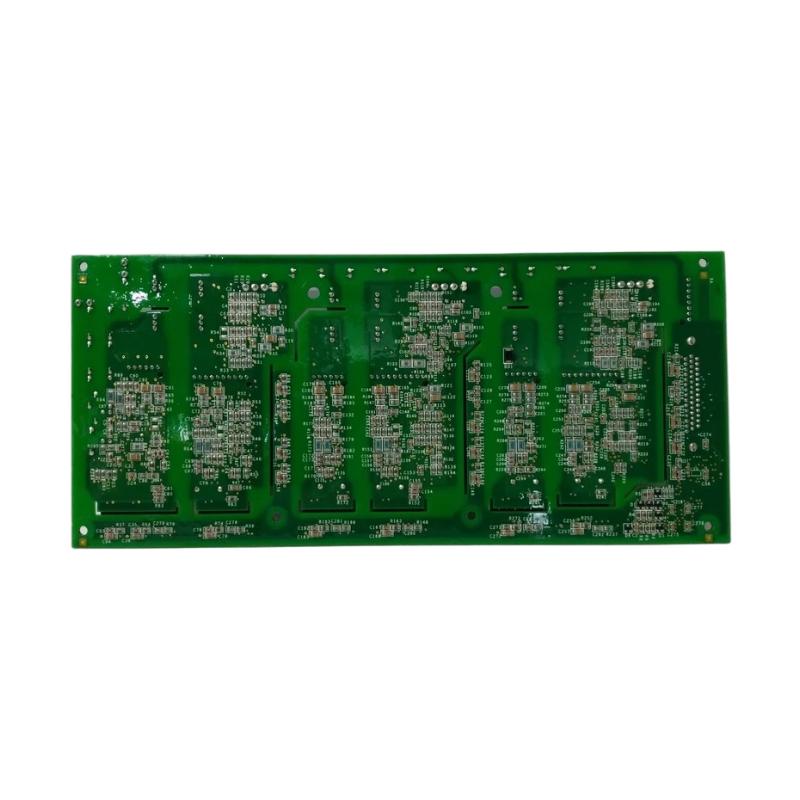
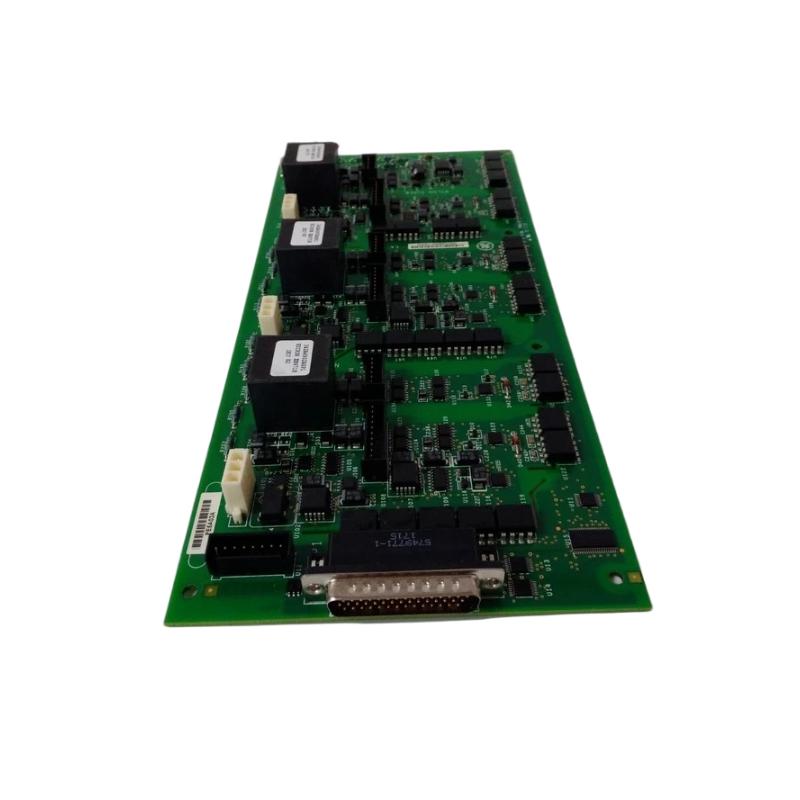
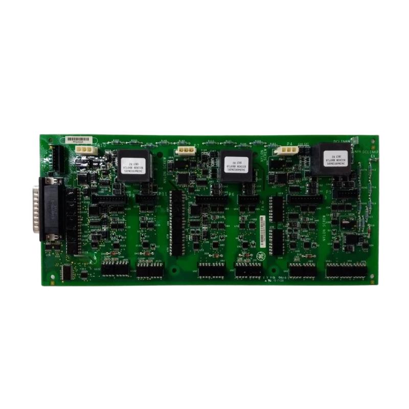
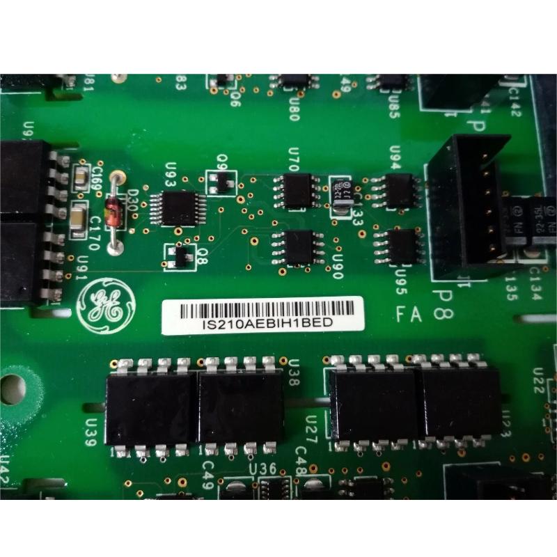
- GE
- IS210AEBIH1BED
- Bridge Interface Board
- USA
- 280 x 20 x 140 mm
- 0.45 kg
- Xiamen, China
- New & In Stock
- T/T, PayPal, Western Union
- 1 Year
- 1-3 Working Days
- DHL, UPS, TNT, FedEx and EMS.
- 24-Hour Service
- COO
- 5
Our advantage

Global Logistics
We have a 10-year logistics and express cooperation agreement, so our products can be shipped to any place in the world.

Brand new and original
Our products are imported in bulk from the place of origin. Because of the cooperative relationship, our products are all original and 100% new.

24-hour service
We provide 7*24 hours service to our customers. We will be there whenever you need us.

Price advantage
All our products are priced very favorably because we have our own warehouse and supply.
| Company Information | |||
| [email protected] | |||
| Mobile | +8615980777398 | ||
| +8615980777398 | |||
| 15980777398 |
Product Overview
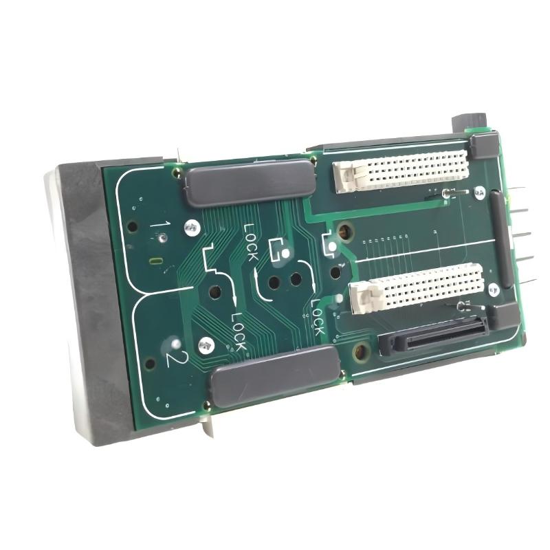
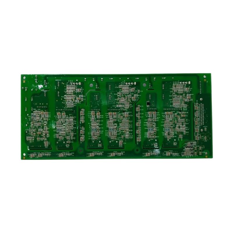
The GE IS210AEBIH1BED Bridge Interface Board is a specialized electronic circuit board designed for use within GE industrial control and automation systems. As part of the GE IS210 family, the board provides an interface between related control-system circuitry and associated bridge or power-interface functions, helping establish reliable signal connections within a larger industrial control architecture.
Bridge interface boards are commonly used where multiple electronic assemblies must exchange control, feedback, or interface signals in a coordinated manner. In an industrial control system, the interface between control electronics and power-related equipment is critical because reliable signal transmission is required for monitoring, protection, regulation, and system coordination.
The GE IS210AEBIH1BED has listed dimensions of 280 × 20 × 140 mm and a weight of approximately 0.45 kg. Its relatively narrow board profile allows it to be installed within compact industrial control equipment while maintaining the physical connections required by the host system.
The exact electrical function of an individual IS210 board depends on the equipment configuration in which it is installed. Therefore, the complete board identification, revision, connector arrangement, and host-system application should always be verified before installation or replacement.
Technical Specifications
| Parameter | Specification |
|---|---|
| Manufacturer | General Electric (GE) |
| Model | IS210AEBIH1BED |
| Product Type | Bridge Interface Board |
| Product Family | GE IS210 Series |
| Primary Function | Bridge interface and signal interconnection |
| Application | Industrial Control and Automation |
| Board Type | Interface / Control Circuit Board |
| Dimensions | 280 × 20 × 140 mm |
| Weight | 0.45 kg |
| Installation | Compatible GE industrial control equipment |
| System Role | Interface between associated control-system assemblies |
| Typical Application | Industrial control, monitoring, interface and system integration |
What Is the GE IS210AEBIH1BED?
The GE IS210AEBIH1BED is a GE industrial circuit board identified as a Bridge Interface Board. It is designed to operate as part of a larger control architecture rather than as an independent controller.
In complex industrial automation equipment, individual circuit boards normally perform specialized functions. Some boards provide processing, others handle I/O, communications, feedback, excitation, protection, or signal conditioning. Interface boards provide the electrical interconnection required for these different functional sections to operate together.
The IS210AEBIH1BED therefore forms part of the communication and signal-interface layer within its compatible GE control equipment.
A simplified system relationship can be represented as:
Control Logic → Interface Board → Bridge / Associated Circuitry → Field or Power Equipment
The actual signal path depends on the specific GE system and hardware configuration.
Function and Working Principle
Signal Interconnection
The primary role of an interface board is to provide a controlled connection between different sections of an industrial control system.
The IS210AEBIH1BED can form part of an electrical pathway through which control, status, feedback, or other system signals are exchanged between associated assemblies.
Bridge Interface Function
The term Bridge Interface Board indicates that the board is associated with an interface between control electronics and bridge-related circuitry.
In industrial power and control equipment, bridge circuits may be associated with power conversion, excitation, switching, or other controlled electrical functions. The interface electronics provide the necessary connection between the control architecture and these associated circuits.
The exact electrical characteristics should be confirmed against the documentation for the specific host system.
Signal Management
Reliable signal management is essential for industrial control applications. A properly functioning interface board helps maintain the electrical connection between the relevant system assemblies.
Depending on the application, signals passing through the interface architecture may support:
- Control commands
- Status information
- Feedback signals
- Protection information
- Monitoring signals
- System coordination signals
The exact signal types depend on the host equipment.
System Coordination
Industrial control systems often contain several boards operating together. An interface board helps these assemblies function as a coordinated system rather than as isolated electronic components.
This architecture makes it possible for processing boards, interface assemblies, power electronics, sensors, and other system components to exchange the information required for normal operation.
Role in GE Industrial Control Systems
The IS210AEBIH1BED Bridge Interface Board can be considered part of the interface layer of a GE industrial control system.
A typical industrial architecture may contain several functional levels:
Operator Interface → Control Processor → Interface Electronics → Power / Field Equipment
At the board level, the interface assembly helps connect the control logic with associated electrical equipment.
This type of architecture is particularly important in applications where reliable coordination between low-level control electronics and higher-power equipment is required.
A correctly functioning interface board can contribute to:
- Reliable signal transmission
- Control-system coordination
- Equipment monitoring
- Protection-system communication
- Feedback processing
- Stable operation of associated equipment
The exact contribution of the IS210AEBIH1BED depends on the GE platform and system in which it is installed.
Industrial Applications
Power Generation
GE industrial control systems are widely associated with power-generation equipment. Interface boards can be used within control architectures where control electronics must communicate with electrical conversion, excitation, turbine, generator, or auxiliary equipment.
The IS210AEBIH1BED may therefore be encountered in industrial environments where bridge-related control functions form part of the overall system.
Generator Control
Generator systems require coordinated monitoring and control of electrical and mechanical operating conditions. Interface circuitry can provide the connection between control logic and associated electrical assemblies.
Excitation and Electrical Control
Interface boards can also form part of larger electrical-control architectures in which bridge or power-control circuitry must receive commands and return feedback to the main control system.
Industrial Automation
Beyond power-generation equipment, specialized interface boards can support complex industrial automation systems where multiple electronic assemblies must exchange signals reliably.
Retrofit and Maintenance Applications
Older industrial control systems can remain in service for many years. Replacement interface boards are therefore important for maintenance, repair, and system refurbishment.
When servicing an existing installation, the exact IS210AEBIH1BED identification should be matched before replacement.
System Integration
The IS210AEBIH1BED should be regarded as one component within a larger GE control-system architecture.
A typical integration structure may include:
| System Component | General Function |
|---|---|
| Control Processor | Executes control logic |
| Interface Board | Connects associated electronic assemblies |
| Bridge / Power Circuitry | Performs associated electrical function |
| Feedback Circuitry | Provides operating information |
| I/O Assemblies | Connect field signals |
| Communication Interfaces | Exchange system data |
| Operator Interface | Provides monitoring and control |
| Power Supply | Provides required electrical power |
The exact combination of components varies according to the host equipment.
Because different GE systems can use boards with similar physical construction, compatibility should never be determined from dimensions or appearance alone.
Installation Guidelines
Proper installation is important when replacing the GE IS210AEBIH1BED Bridge Interface Board.
Verify the Part Number
Before removing the existing board, record the complete identification:
- IS210AEBIH1BED
- Board revision
- Board labels
- Connector locations
- Cable connections
- Host equipment identification
- Existing board position
The complete part number should be compared with the replacement board.
Disconnect System Power
The associated equipment should be placed into an appropriate maintenance condition before board replacement. Power isolation and discharge procedures must follow the applicable GE equipment maintenance requirements.
Electronic control equipment can contain hazardous voltages even after normal operation has stopped.
Record Connections
Before removing the original board, technicians should document cable and connector locations.
Photographs, wiring records, and equipment drawings can help reduce the possibility of incorrect reconnection.
Inspect Connectors
Connectors should be inspected for:
- Bent contacts
- Contamination
- Corrosion
- Mechanical damage
- Loose connections
- Signs of overheating
A damaged connector can produce symptoms that appear to be caused by the circuit board.
Install the Replacement Board
The replacement board should be installed in the correct physical position using appropriate handling procedures.
Avoid unnecessary contact with exposed electronic components and protect the board from electrostatic discharge.
Commissioning Procedure
After installation, the system should be commissioned carefully.
Step 1: Verify Board Installation
Confirm that the board is correctly seated and mechanically secured.
Step 2: Check Connectors
Verify every connector and cable against the original installation documentation.
Step 3: Inspect the Assembly
Look for loose cables, damaged connectors, foreign objects, or visible signs of abnormal conditions.
Step 4: Restore Power
Restore system power according to the applicable equipment startup procedure.
Step 5: Check System Diagnostics
Review available control-system diagnostics for board-related alarms, communication problems, or other abnormal conditions.
Step 6: Verify Normal Operation
Operate the equipment under controlled conditions and confirm that the associated control and monitoring functions behave as expected.
Troubleshooting the IS210AEBIH1BED
A suspected interface-board problem should be investigated as part of the complete control system.
No Signal or Communication
If an associated system does not receive the expected signal, inspect:
- Board connectors
- Signal cables
- Power supply
- Related interface assemblies
- Control-system configuration
- Associated bridge circuitry
- Diagnostic indications
A connection problem can produce symptoms similar to a failed board.
Intermittent Operation
Intermittent behavior may be caused by:
- Loose connectors
- Damaged cables
- Vibration
- Contamination
- Electrical interference
- Thermal conditions
- Board-level component degradation
Inspect the physical connections before replacing the board.
Unexpected System Alarm
If a system alarm appears after board replacement, verify:
- Correct board model
- Correct board revision
- Correct connector locations
- Correct cable routing
- Correct system configuration
- Associated equipment condition
A mismatch between the installed board and the host-system configuration can result in abnormal operation.
Board Appears Inactive
If the board does not appear to operate, verify the associated power and interface conditions before concluding that the board has failed.
The fault may originate from another assembly supplying power or signals to the interface board.
Preventive Maintenance
Regular inspection can help reduce unexpected control-system downtime.
Inspect Connectors
Connectors should be checked periodically for looseness, contamination, corrosion, and mechanical damage.
Check Wiring
Associated cables should be inspected for:
- Cuts
- Abrasion
- Loose connections
- Excessive bending
- Heat damage
- Insulation deterioration
Monitor System Diagnostics
Historical alarms and diagnostic records can provide useful information about developing problems.
Maintain Cabinet Conditions
The control cabinet should be maintained in a clean and controlled environment. Excessive dust, moisture, heat, and vibration can negatively affect electronic assemblies.
Avoid Unnecessary Board Handling
Circuit boards should not be removed or exchanged unnecessarily. Frequent handling increases the risk of connector damage and electrostatic discharge.
Physical Dimensions and Weight
The listed physical dimensions of the GE IS210AEBIH1BED are:
280 × 20 × 140 mm
The listed weight is:
0.45 kg
These dimensions are useful for:
- Spare-parts inventory planning
- Cabinet layout
- Replacement preparation
- Shipping arrangements
- Maintenance planning
- Equipment documentation
The 20 mm dimension indicates the board’s relatively narrow physical profile, which can be useful in compact control assemblies.
Physical dimensions alone, however, should not be used to determine electrical compatibility.
Replacement Considerations
When sourcing a replacement GE IS210AEBIH1BED, the complete identification should be checked carefully.
Important information includes:
- Full model number
- Revision designation
- Board labels
- Connector arrangement
- Host equipment
- Existing installation position
- Associated boards
- System configuration
GE industrial control boards can have similar physical dimensions while serving completely different functions.
Therefore, a board should not be considered interchangeable simply because its size or connector arrangement appears similar.
For maintenance inventory, the full IS210AEBIH1BED designation should be recorded rather than relying on a shortened model number.
Related GE Control Components
The IS210AEBIH1BED may be integrated into a larger GE industrial control environment containing components such as:
- GE IS200 series circuit boards
- GE IS210 series interface boards
- Control processor boards
- I/O interface boards
- Communication boards
- Feedback boards
- Excitation-control assemblies
- Power interface assemblies
- Terminal boards
- Industrial control power supplies
The exact compatible components depend on the host equipment and system revision.
When designing a replacement strategy, the entire control-system architecture should be considered rather than evaluating the interface board independently.
Engineering Best Practices
For reliable use of the GE IS210AEBIH1BED Bridge Interface Board, several engineering practices are recommended.
Maintain Accurate Part Records
Record the complete board number and revision in the maintenance database.
Keep Critical Spares Available
For equipment where downtime is costly, maintaining an appropriately identified spare interface board can reduce repair time.
Document Cable Connections
Clear cable documentation makes future replacement work faster and reduces wiring errors.
Control Environmental Conditions
Electronic assemblies should be protected from excessive heat, moisture, dust, vibration, and contamination.
Use Controlled Commissioning
After replacement, verify system behavior progressively instead of immediately returning the equipment to full operating conditions.
Investigate Root Causes
If a board repeatedly fails, investigate power quality, thermal conditions, vibration, wiring, connected equipment, and environmental conditions rather than repeatedly replacing the board without determining the underlying cause.
Key Advantages
The GE IS210AEBIH1BED Bridge Interface Board offers several practical characteristics for industrial control applications:
- Specialized bridge interface functionality
- Integration within GE industrial control architectures
- Compact 280 × 20 × 140 mm physical design
- Listed weight of 0.45 kg
- Suitable for complex electronic control assemblies
- Supports coordinated operation between associated system components
- Useful for maintenance and replacement applications
- Designed for integration into compatible GE control equipment
Technical FAQs
What is the GE IS210AEBIH1BED?
The GE IS210AEBIH1BED is a Bridge Interface Board used as part of compatible GE industrial control and automation equipment.
What is the primary function of the IS210AEBIH1BED?
Its primary role is to provide bridge-related interface and signal interconnection functionality within the associated control-system architecture.
What are the dimensions of the IS210AEBIH1BED?
The listed dimensions are 280 × 20 × 140 mm.
How much does the IS210AEBIH1BED weigh?
The listed weight is approximately 0.45 kg.
Is the IS210AEBIH1BED a PLC?
No. It is a specialized industrial circuit board rather than a general-purpose PLC CPU.
Can another GE IS210 board replace the IS210AEBIH1BED?
A different IS210 board should not be assumed to be interchangeable. The complete model number, revision, connector arrangement, and host-system requirements must be verified.
What can cause an interface-board fault?
Potential causes include connector problems, damaged wiring, environmental conditions, power issues, electrical interference, associated equipment faults, or failure of components on the board itself.
What should be checked before replacing the board?
Technicians should verify the full board number, revision, connectors, cables, host equipment, system configuration, and associated circuitry before replacement.
Where is the IS210AEBIH1BED used?
It is intended for compatible GE industrial control equipment where bridge interface functionality is required. The exact application depends on the host system.
Conclusion
The GE IS210AEBIH1BED Bridge Interface Board is a specialized electronic interface component designed for integration into compatible GE industrial control systems. Its role is centered on providing reliable interconnection between associated control electronics and bridge-related circuitry, allowing different sections of the industrial control architecture to operate together.
With listed dimensions of 280 × 20 × 140 mm and a weight of 0.45 kg, the board provides a compact form factor suitable for integration into industrial electronic assemblies.
For replacement, maintenance, or system refurbishment, technicians should verify the complete IS210AEBIH1BED identification, revision, connector arrangement, and host-system compatibility before installation. Proper wiring, controlled commissioning, environmental management, and systematic troubleshooting are essential for maintaining reliable operation of the associated GE industrial control equipment.