

ProductPRODUCT
Featured products
Contact Us
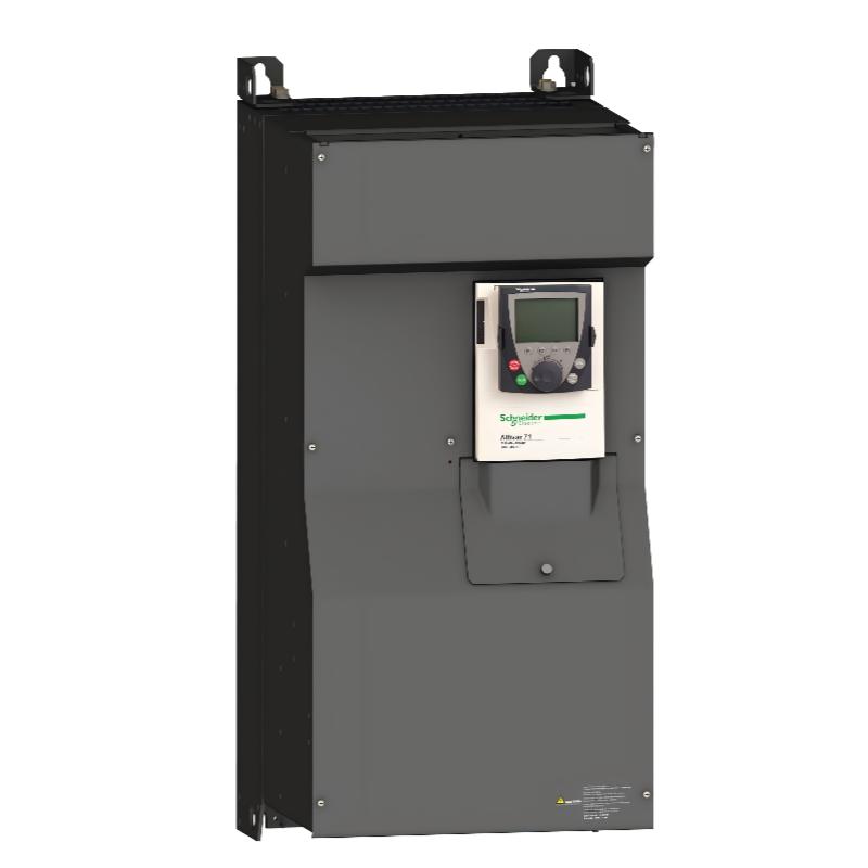
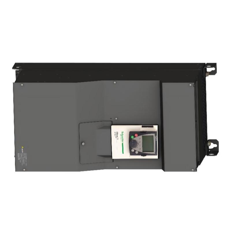
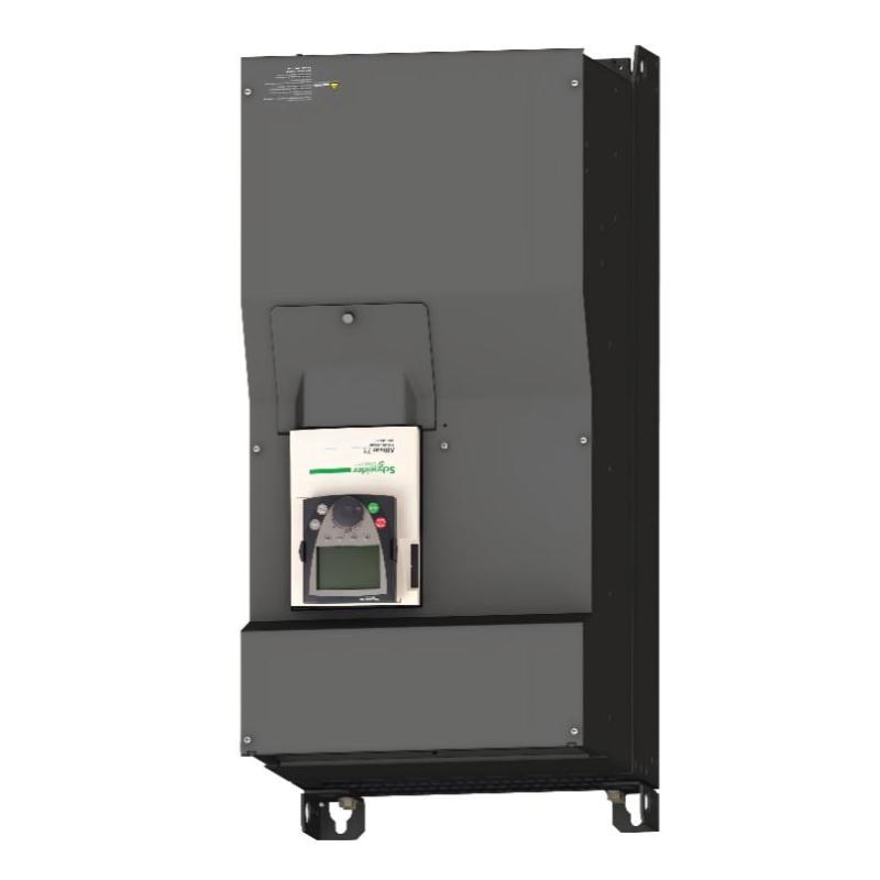
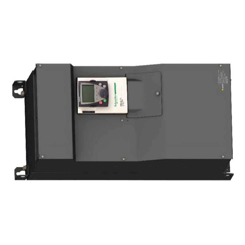
- Schneider
- ATV71HC13N4
- Transmission Drive
- France
- 1190 × 340 × 377 mm
- 116 kg
- Xiamen, China
- New & In Stock
- T/T, PayPal, Western Union
- 1 Year
- 1-3 Working Days
- DHL, UPS, TNT, FedEx and EMS.
- 24-Hour Service
- COO
- 5
Our advantage

Global Logistics
We have a 10-year logistics and express cooperation agreement, so our products can be shipped to any place in the world.

Brand new and original
Our products are imported in bulk from the place of origin. Because of the cooperative relationship, our products are all original and 100% new.

24-hour service
We provide 7*24 hours service to our customers. We will be there whenever you need us.

Price advantage
All our products are priced very favorably because we have our own warehouse and supply.
| Company Information | |||
| [email protected] | |||
| Mobile | +8615980777398 | ||
| +8615980777398 | |||
| 15980777398 |
Product Overview
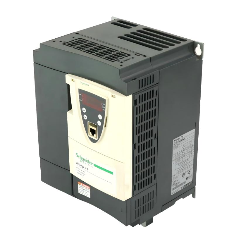
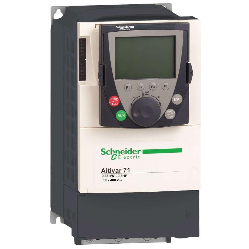
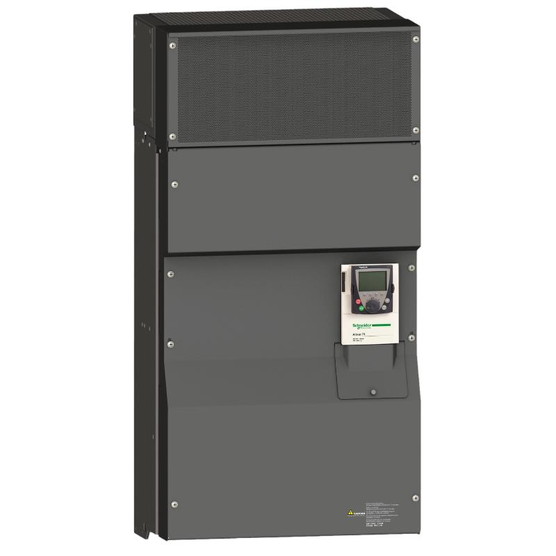
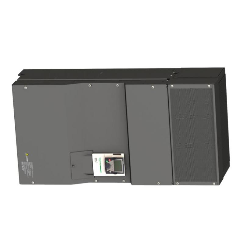
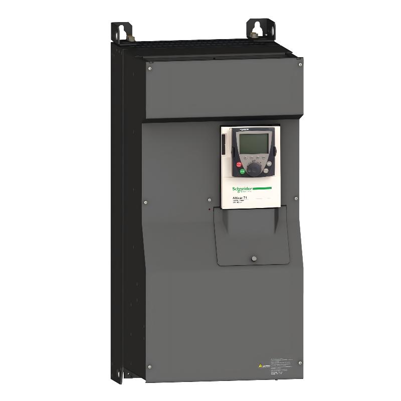
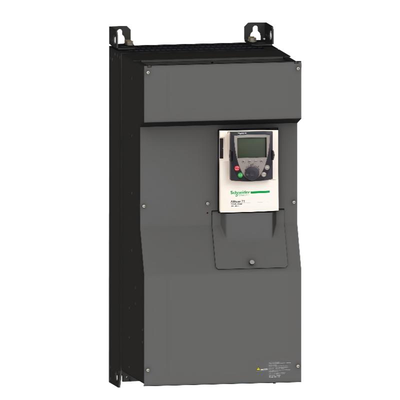
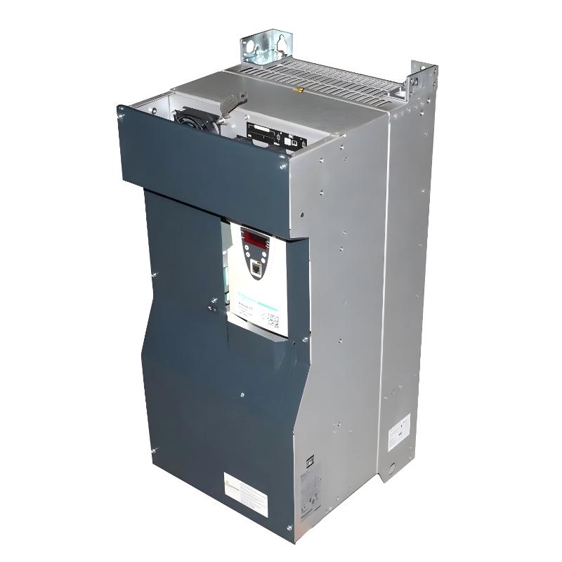
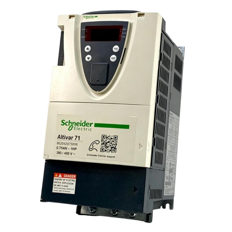
The Schneider ATV71HC13N4 Transmission Drive is a high-power industrial motor control solution belonging to the Schneider Electric Altivar 71 family. Designed for demanding transmission and variable-speed applications, this drive provides controlled operation of three-phase AC motors used in large industrial machines, conveyors, pumps, fans, compressors, material-handling equipment, and process machinery.
The purpose of a transmission drive is to provide a controlled interface between the electrical power system and the mechanical transmission system. Instead of operating a motor at a fixed electrical frequency, the drive allows motor speed and torque to be managed according to the requirements of the connected equipment. This can improve machine flexibility while reducing mechanical stress during starting, acceleration, speed changes, and stopping.
The ATV71HC13N4 is intended for high-power industrial applications where substantial motor capacity and robust drive-system performance are required. Its large physical format reflects the requirements of high-power power-electronic equipment. The listed dimensions are 1190 × 340 × 377 mm, and the listed weight is 116 kg.
Because of its size and weight, the ATV71HC13N4 requires careful engineering during cabinet design, transportation, lifting, installation, ventilation, and electrical connection. It is best suited to fixed industrial installations where the drive forms part of a complete motor-control and automation architecture.
Technical Specifications
| Parameter | Specification |
|---|---|
| Manufacturer | Schneider Electric |
| Model | ATV71HC13N4 |
| Product Series | Altivar 71 |
| Product Type | Transmission Drive / Variable Speed Drive |
| Motor Control | Adjustable AC Motor Speed and Torque Control |
| Motor Type | Three-Phase AC Motors |
| Application Class | High-Power Industrial Motor Control |
| Dimensions | 1190 × 340 × 377 mm |
| Weight | 116 kg |
| Installation | Industrial Cabinet / Fixed Installation |
| Control Application | Motor Speed, Torque and Process Control |
| Typical Applications | Conveyors, Pumps, Fans, Compressors, Material Handling and Process Machinery |
Detailed electrical ratings and configuration parameters should be verified from the exact product identification, hardware revision, motor nameplate, and application requirements.
What Is the Schneider ATV71HC13N4?
The Schneider ATV71HC13N4 is a high-power Transmission Drive designed to regulate the operation of industrial AC motors.
In a conventional fixed-speed motor installation, the motor is generally connected to a fixed electrical supply and operates around a predetermined speed. A variable speed drive introduces an additional layer of control between the power source and motor.
The general system arrangement can be represented as:
Industrial Power Supply → Protection Equipment → ATV71HC13N4 → AC Motor → Transmission System → Machine Load
The transmission system may include gearboxes, couplings, belts, shafts, pulleys, rollers, pumps, fans, or other mechanical components.
The drive controls the motor while the mechanical transmission transfers the resulting power to the final load.
This makes the ATV71HC13N4 particularly useful when a machine needs controlled acceleration, adjustable speed, controlled torque, or coordinated operation with an automation controller.
Transmission Drive Working Principle
The operating principle of the ATV71HC13N4 is based on controlled power conversion.
AC Input
The drive receives electrical power from the industrial power system.
Power Conversion
The incoming electrical energy passes through the drive’s power-conversion stages to create a controlled intermediate electrical supply.
Inverter Switching
The inverter section uses controlled semiconductor switching to produce an adjustable output for the motor.
Frequency and Voltage Regulation
By controlling the characteristics of the motor supply, the drive can regulate motor speed and influence torque behavior.
Mechanical Transmission
The motor transfers mechanical energy through the transmission system to the driven machine.
Process Response
The drive can change motor operating conditions according to commands from an operator, PLC, controller, or other automation system.
This allows the complete transmission system to respond to changing production requirements.
Speed and Torque Control
Large industrial transmission systems often experience changing loads.
For example, a conveyor may start with no material and then progressively become loaded. A pump may experience different flow requirements. A fan may need to change airflow according to process demand.
The ATV71HC13N4 provides a controlled method of managing motor operation under these changing conditions.
Potential benefits include:
- Adjustable motor speed
- Controlled acceleration
- Controlled deceleration
- Improved torque management
- Reduced mechanical shock
- Smoother machine operation
- Better process flexibility
- Improved coordination between motor and machine
The appropriate control mode should be selected according to the motor, mechanical load, and required machine behavior.
Role in Industrial Automation
The ATV71HC13N4 can serve as the power-control layer between an industrial automation controller and a high-power mechanical system.
A typical architecture is:
Sensors → PLC / Controller → ATV71HC13N4 → Motor → Transmission → Machine
Sensors can provide information about:
- Speed
- Pressure
- Flow
- Position
- Temperature
- Level
- Load
- Production conditions
The PLC or controller processes this information and determines the required motor command.
The ATV71HC13N4 then translates the control command into appropriate motor operation.
This architecture allows the automation controller to focus on process logic while the drive handles the electrical motor-control function.
Industrial Applications
Conveyor and Transmission Systems
Large conveyors frequently require controlled acceleration and adjustable operating speed.
A transmission drive can reduce sudden mechanical loading on:
- Belts
- Gearboxes
- Shafts
- Couplings
- Rollers
- Bearings
This is particularly valuable for conveyors with high inertia or substantial transported loads.
Pumping Equipment
Large pumps can benefit from adjustable motor speed when process flow or pressure requirements change.
Variable speed operation can help match pump output to actual process demand.
Industrial Fans
High-capacity ventilation and air-handling systems may require different airflow levels throughout the production cycle.
Drive-based speed regulation allows the fan motor to operate according to the required ventilation level.
Compressors
Industrial compressors can require controlled starting and stable operation under changing process conditions.
A properly configured drive can form part of a complete compressor-control architecture.
Material Handling
Heavy material-handling equipment often has significant mechanical inertia.
Controlled acceleration and deceleration can help reduce mechanical stress while improving operating smoothness.
Process Machinery
The ATV71HC13N4 can be incorporated into industrial process equipment where motor speed and torque need to be controlled according to process requirements.
PLC Integration
A PLC can supervise the ATV71HC13N4 as part of an automated industrial system.
Depending on the control architecture, commands may include:
- Start
- Stop
- Enable
- Speed reference
- Direction
- Operating mode
- Fault reset
- Process-specific control commands
The drive can also provide status and diagnostic information to the controller.
Typical information used by the automation system may include:
- Drive ready status
- Running status
- Fault status
- Warning status
- Operating state
- Speed information
- Diagnostic conditions
The actual interface and communication method should be selected according to the installed drive configuration.
HMI and SCADA Integration
High-power drives are often installed in systems where operators need centralized visibility of machine performance.
An HMI can provide operators with information such as:
- Motor running status
- Drive operating status
- Speed reference
- Actual operating values
- Alarm information
- Fault information
- Maintenance-related information
For larger plants, multiple drives can be monitored through a SCADA system.
Centralized monitoring makes it easier to identify abnormal conditions and coordinate maintenance activities.
Installation Guidelines
The ATV71HC13N4 is a large industrial drive with listed dimensions of 1190 × 340 × 377 mm and a weight of 116 kg.
Installation should therefore be planned as a major mechanical and electrical engineering task.
Before installation, verify:
- Cabinet dimensions
- Mounting structure
- Floor or enclosure loading capacity
- Lifting equipment
- Cable entry arrangement
- Ventilation
- Electrical clearances
- Grounding
- Power distribution
- Motor cable routing
- Environmental conditions
The mounting structure must be capable of safely supporting the listed 116 kg weight.
Appropriate lifting and handling equipment should be used when moving and positioning the drive.
Cabinet Design and Thermal Management
High-power drives produce heat during operation. Proper thermal management is therefore essential.
The cabinet should be designed to maintain suitable operating conditions for the drive and associated equipment.
Important factors include:
Airflow
Adequate airflow should be provided to prevent excessive heat accumulation.
Heat Sources
Transformers, contactors, reactors, braking equipment, and other heat-producing components should be positioned carefully.
Ventilation
The cabinet ventilation arrangement should account for the drive’s operating heat load.
Dust Control
Dust can accumulate on cooling surfaces and reduce thermal performance.
Environmental Conditions
The installation should be protected from excessive moisture, conductive dust, corrosive materials, and excessive vibration.
Power and Motor Wiring
The general system arrangement is:
Incoming Supply → Electrical Protection → ATV71HC13N4 → Motor → Transmission
The protective devices and cable sizes should be selected for the complete electrical system.
Before energizing the drive, technicians should verify:
- Incoming power connections
- Motor terminals
- Grounding
- Cable insulation
- Terminal tightness
- Protection devices
- Control circuits
- Interlock circuits
Motor cables should be selected according to motor characteristics, current requirements, cable length, installation method, and applicable electrical standards.
EMC and Cable Routing
High-power variable speed drives use high-speed switching devices. Electromagnetic compatibility should therefore be considered during system design.
Recommended engineering practices include:
- Separate control and power wiring
- Route motor cables carefully
- Use appropriate shielded cables where required
- Maintain suitable grounding
- Avoid unnecessary cable loops
- Separate communication cables from high-power conductors
- Minimize parallel routing between sensitive signal cables and motor cables
Correct cable management can help reduce electrical interference and improve the stability of control and communication systems.
Motor and Application Configuration
Correct parameter configuration is important for reliable operation.
Before commissioning, engineers should collect the motor’s nameplate information, including the applicable:
- Motor power
- Rated voltage
- Rated current
- Rated frequency
- Rated speed
- Motor connection
- Application load characteristics
The drive should then be configured according to the selected control strategy.
For a transmission application, particular attention should be given to acceleration, deceleration, operating speed, torque requirements, and mechanical inertia.
Commissioning Procedure
A systematic commissioning procedure can reduce startup problems.
Step 1: Mechanical Inspection
Verify that the drive is securely mounted and that the support structure can safely carry the 116 kg listed weight.
Step 2: Electrical Inspection
Check power wiring, motor wiring, grounding, protection devices, and control circuits.
Step 3: Motor Verification
Compare motor nameplate information with the intended drive configuration.
Step 4: Parameter Configuration
Enter the applicable motor and application parameters.
Step 5: Control Configuration
Configure the source of the start command and speed reference.
Step 6: Direction Test
Perform a controlled low-speed test and verify the motor rotation direction.
Step 7: Acceleration Test
Test the configured acceleration behavior and monitor the motor and transmission system.
Step 8: Load Test
Gradually apply the mechanical load and observe drive and motor performance.
Step 9: Automation Test
Verify PLC commands, HMI functions, alarms, interlocks, communication, and emergency stopping functions.
Troubleshooting the ATV71HC13N4
Troubleshooting should consider the drive, motor, transmission, mechanical load, power supply, and control system as one complete system.
Drive Does Not Start
Possible areas to inspect include:
- Incoming power
- Start command
- Enable condition
- Active fault
- External interlock
- Speed reference
- Motor configuration
- PLC logic
The control command should be traced from the PLC or operator interface to the drive.
Motor Does Not Rotate
Check:
- Motor wiring
- Motor terminals
- Drive output
- Mechanical coupling
- Motor condition
- Mechanical obstruction
- Control command
A mechanical problem can produce symptoms similar to an electrical drive fault.
Motor Speed Is Incorrect
Potential causes include:
- Incorrect speed reference
- Incorrect parameter settings
- PLC scaling
- Communication configuration
- Motor data
- Mechanical transmission problems
The complete command chain should be inspected.
Drive Trips During Acceleration
Possible causes include:
- Excessive mechanical inertia
- Heavy load
- Incorrect acceleration configuration
- Motor problems
- Supply problems
- Mechanical obstruction
- Incorrect application settings
The transmission and driven equipment should be inspected together with the drive.
Excessive Heating
Check:
- Cabinet ventilation
- Cooling airflow
- Ambient temperature
- Motor load
- Drive loading
- Motor condition
- Dust accumulation
Thermal problems should be corrected before prolonged operation.
Preventive Maintenance
High-power transmission drives benefit from systematic preventive maintenance.
Cooling System Inspection
Check ventilation paths and cooling equipment regularly.
Cabinet Cleaning
Remove accumulated dust and contamination using appropriate maintenance procedures.
Terminal Inspection
Inspect electrical terminals for looseness, discoloration, corrosion, or overheating.
Cable Inspection
Inspect motor, power, control, and communication cables for mechanical damage.
Mechanical Inspection
Because the drive controls a transmission system, maintenance should also include gearboxes, couplings, shafts, bearings, belts, and other mechanical components.
Fault History Review
Review drive warnings and fault records where available.
Repeated alarms can indicate developing problems that should be addressed before a major failure occurs.
Replacement and Spare-Part Planning
Replacement planning for the ATV71HC13N4 should cover both electrical compatibility and mechanical handling.
Before ordering a replacement, verify:
- Complete model number
- Product series
- Hardware revision
- Motor characteristics
- Electrical supply
- Control architecture
- Communication requirements
- Cabinet dimensions
- Mounting arrangement
- Cable configuration
- Environmental conditions
The listed physical dimensions are 1190 × 340 × 377 mm, and the listed weight is 116 kg.
These values should be considered when planning transportation, storage, lifting, cabinet installation, and maintenance access.
A drive with similar dimensions should not automatically be considered electrically compatible.
Compatible System Components
The ATV71HC13N4 can be integrated with a range of industrial control and power-system components.
| Component | Typical Function |
|---|---|
| Three-Phase AC Motor | Provides mechanical power |
| Gearbox / Transmission | Transfers and adapts mechanical power |
| PLC Controller | Executes machine and process logic |
| HMI | Provides operator monitoring and control |
| SCADA System | Provides supervisory monitoring |
| Circuit Breaker | Electrical circuit protection |
| Motor Protection Equipment | Supports motor protection |
| Sensors | Provides process feedback |
| Encoder / Feedback Device | Provides speed or position feedback where required |
| Industrial Network | Transfers control and diagnostic information |
| Braking Equipment | Supports controlled deceleration |
| Contactor / Disconnect | Provides switching and isolation |
| Cooling Equipment | Supports thermal management |
The actual system configuration depends on the machine and process requirements.
Recommended Related Schneider Electric Models
| Model | Product Family | General Application |
|---|---|---|
| ATV71H075N4Z | Altivar 71 | Compact variable-speed applications |
| ATV71HU15N4 | Altivar 71 | Industrial motor speed control |
| ATV71HU22N4 | Altivar 71 | Medium-power industrial applications |
| ATV71HC11N4 | Altivar 71 | High-power motor control |
| ATV71HC13N4 | Altivar 71 | High-power transmission applications |
| ATV630D90N4 | Altivar Process ATV600 | Process-oriented motor control |
| ATV650D90N4 | Altivar Process ATV600 | High-power process applications |
| ATV650D110N4 | Altivar Process ATV600 | Large industrial process systems |
These models belong to Schneider Electric variable speed drive families, but they should not be treated as direct replacements without verifying electrical ratings, application requirements, control architecture, and physical installation conditions.
Engineering Considerations
The successful use of a large transmission drive depends on more than selecting a suitable motor power class.
Mechanical Inertia
High-inertia equipment may require carefully configured acceleration and deceleration profiles.
Transmission Characteristics
Gearboxes, belts, couplings, and shafts influence how motor torque reaches the final machine.
Load Profile
The continuous and peak load characteristics should be evaluated during drive selection.
Braking
Applications with frequent stopping or high mechanical inertia may require additional braking considerations.
Cabinet Construction
The cabinet must accommodate the listed 1190 × 340 × 377 mm dimensions while providing suitable structural support.
Handling
The listed 116 kg weight requires appropriate lifting and transportation procedures.
Thermal Design
The heat produced by the drive and surrounding equipment must be included in the cabinet thermal calculation.
Maintenance Access
Sufficient space should be provided around the drive for inspection, testing, cable access, and service activities.
Key Advantages
The Schneider ATV71HC13N4 Transmission Drive provides several advantages for demanding industrial applications:
- High-power Altivar 71 drive platform
- Adjustable AC motor speed control
- Controlled acceleration and deceleration
- Suitable for transmission and process machinery
- Support for motor torque management
- Integration into PLC-based automation systems
- HMI and SCADA integration capability
- Suitable for large conveyor systems
- Applicable to pumps, fans and compressors
- Suitable for heavy material-handling equipment
- Listed dimensions of 1190 × 340 × 377 mm
- Listed weight of 116 kg
- Designed for fixed industrial installation environments
Technical FAQs
What is the Schneider ATV71HC13N4?
The Schneider ATV71HC13N4 is a high-power Transmission Drive / Variable Speed Drive from the Altivar 71 family, designed for industrial AC motor control.
What is the main function of the ATV71HC13N4?
Its main function is to regulate the operating speed and torque of an AC motor and provide controlled motor operation for demanding industrial machinery.
What are the dimensions of the ATV71HC13N4?
The listed dimensions are 1190 × 340 × 377 mm.
How much does the ATV71HC13N4 weigh?
The listed weight is 116 kg.
What applications are suitable for the ATV71HC13N4?
Typical applications include large conveyors, pumps, industrial fans, compressors, material-handling systems, transmission equipment, and other high-power industrial machinery.
Can the ATV71HC13N4 be integrated with a PLC?
Yes. The drive can be incorporated into a PLC-based automation architecture for motor control, status monitoring, fault management, and process coordination.
Why is transmission control important?
A controlled motor drive can provide smoother acceleration and deceleration and can help match motor operation to the requirements of the mechanical transmission and driven equipment.
What should be checked before commissioning?
Engineers should verify motor nameplate information, electrical wiring, grounding, protection, control signals, drive parameters, mechanical transmission condition, and cabinet ventilation.
What can cause repeated drive faults?
Repeated faults may result from excessive mechanical load, incorrect configuration, electrical supply problems, motor problems, insufficient cooling, mechanical obstruction, or incorrect control-system settings.
Can another Altivar model directly replace the ATV71HC13N4?
Not automatically. Electrical ratings, motor requirements, control functions, communication interfaces, dimensions, mounting, and application characteristics must all be evaluated before selecting a replacement.
Conclusion
The Schneider ATV71HC13N4 Transmission Drive is a high-power industrial motor-control solution designed for demanding variable-speed and transmission applications. As part of the Altivar 71 family, it can serve as the interface between a high-power AC motor and the mechanical transmission system, providing controlled acceleration, deceleration, speed regulation, and torque management.
The listed dimensions of 1190 × 340 × 377 mm and weight of 116 kg make mechanical installation and thermal management important engineering considerations. The drive requires an appropriately designed cabinet, adequate structural support, suitable ventilation, proper power and motor wiring, and safe handling procedures.
Within a modern automation system, the ATV71HC13N4 can operate together with PLC controllers, HMIs, SCADA systems, sensors, communication networks, protection equipment, and mechanical transmission components. This allows high-power motor operation to be coordinated with automated production and process-control strategies.
For installation, commissioning, troubleshooting, and replacement, the complete ATV71HC13N4 identification should be verified together with the motor, electrical supply, mechanical load, control architecture, and environmental conditions. When these factors are properly considered, the drive can provide reliable and flexible motor control for demanding industrial transmission systems.