

ProductPRODUCT
Featured products
Contact Us
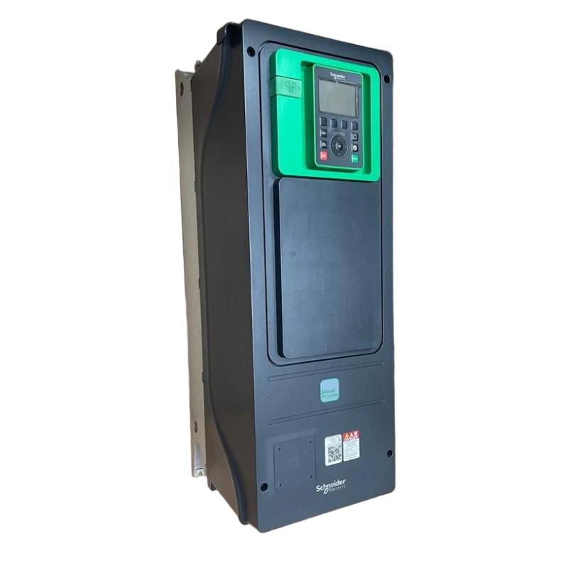
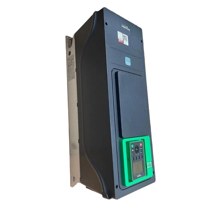
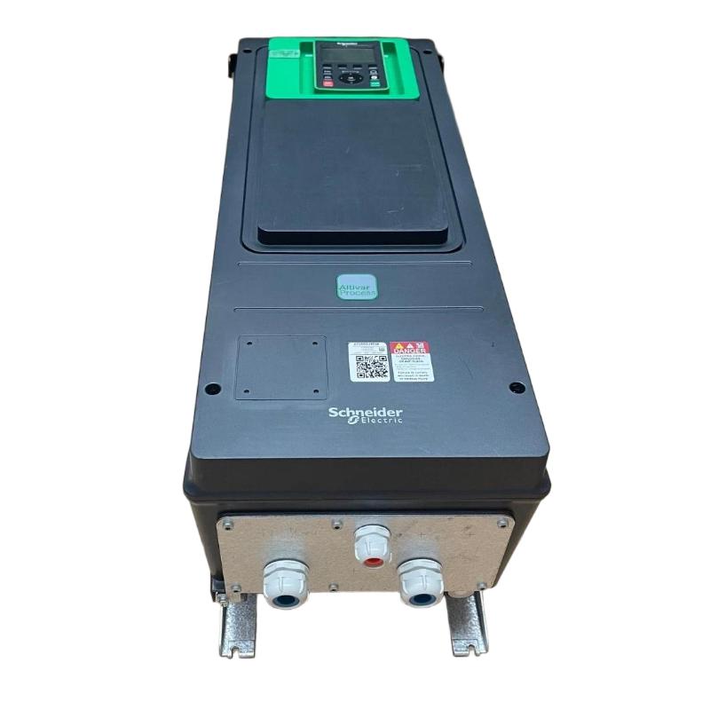
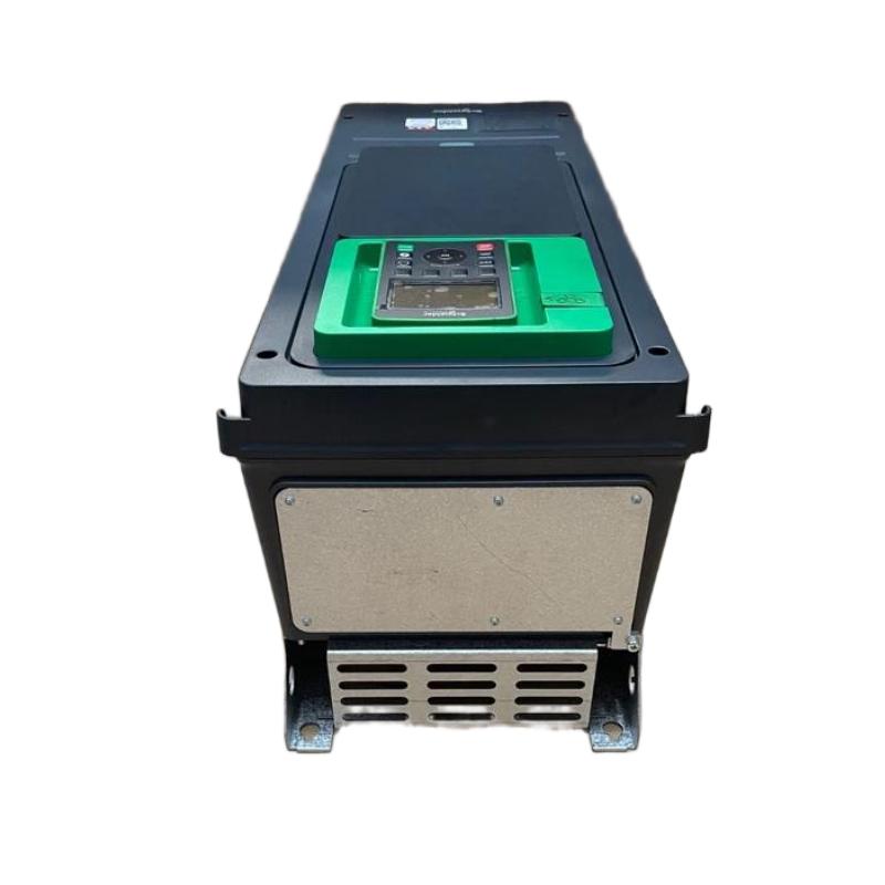
- Schneider
- ATV650U15N4
- Variable Speed Drive
- France
- 264 x 678 x 272 mm
- 10.5 kg
- Xiamen, China
- New & In Stock
- T/T, PayPal, Western Union
- 1 Year
- 1-3 Working Days
- DHL, UPS, TNT, FedEx and EMS.
- 24-Hour Service
- COO
- 4
Our advantage

Global Logistics
We have a 10-year logistics and express cooperation agreement, so our products can be shipped to any place in the world.

Brand new and original
Our products are imported in bulk from the place of origin. Because of the cooperative relationship, our products are all original and 100% new.

24-hour service
We provide 7*24 hours service to our customers. We will be there whenever you need us.

Price advantage
All our products are priced very favorably because we have our own warehouse and supply.
| Company Information | |||
| [email protected] | |||
| Mobile | +8615980777398 | ||
| +8615980777398 | |||
| 15980777398 |
Product Overview
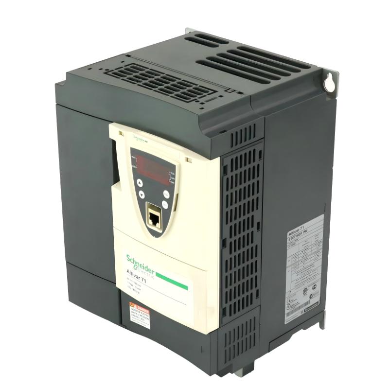
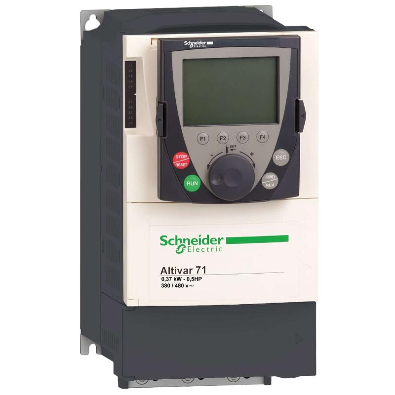
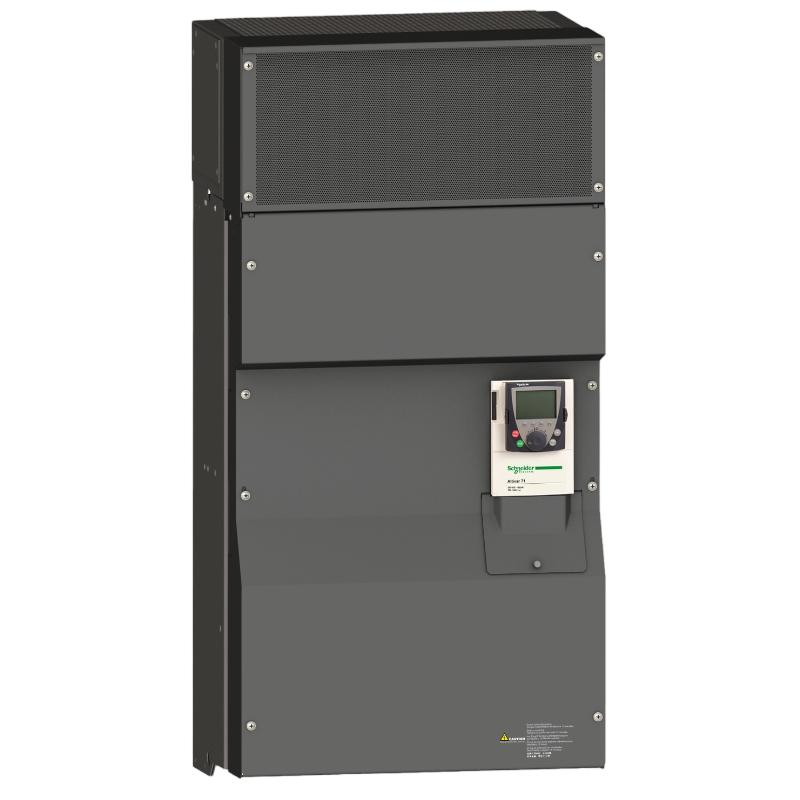
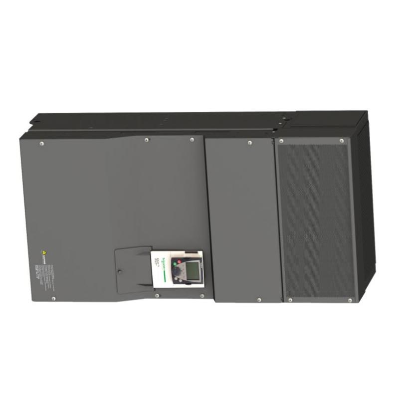
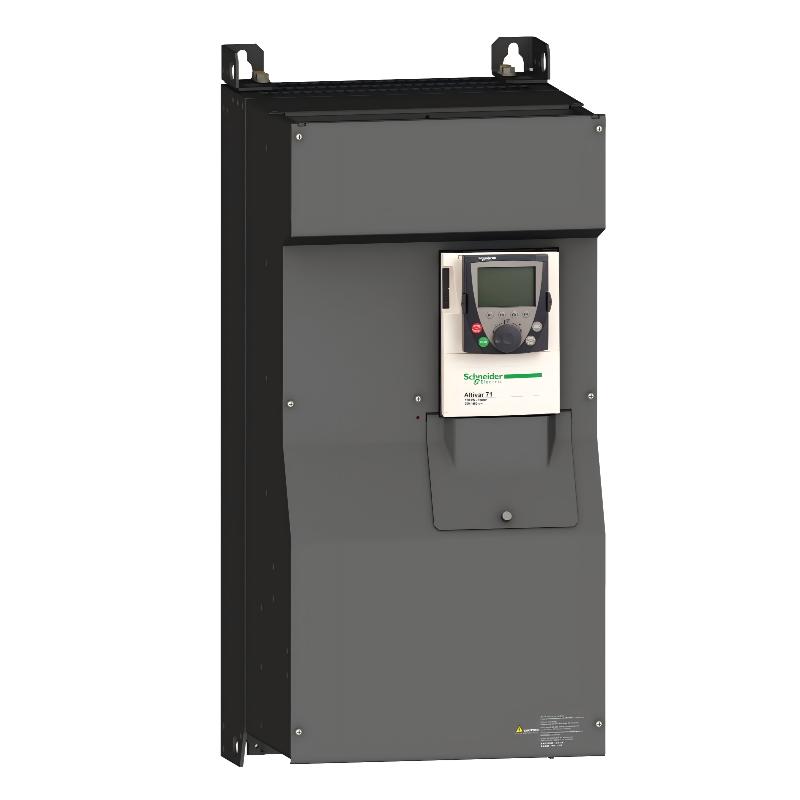
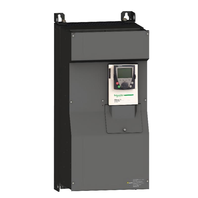
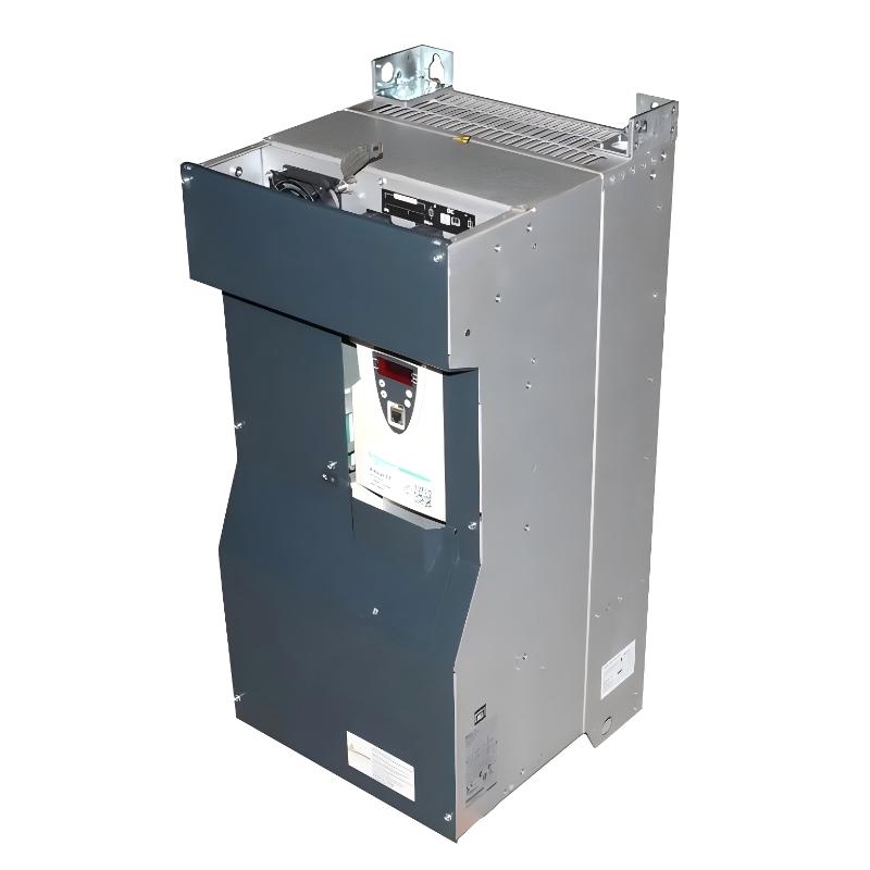
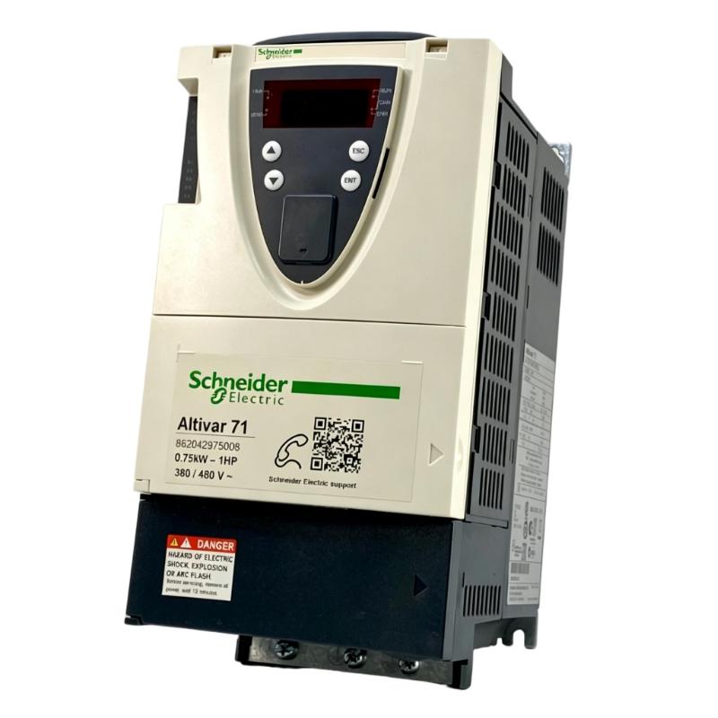
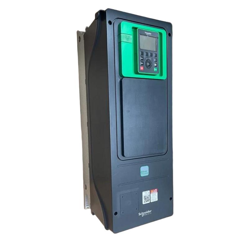
The Schneider Electric ATV650U15N4 Variable Speed Drive is an industrial motor control solution within the Altivar Process ATV650 series, designed for applications requiring adjustable motor speed, dependable process control, energy optimization, and integration with industrial automation systems. It provides an electronic interface between an AC power supply and a compatible motor, allowing motor operation to be adjusted according to process requirements.
The ATV650U15N4 belongs to the 1.5 kW motor power class and is suitable for a variety of industrial applications, including pumps, fans, ventilation equipment, HVAC systems, water-treatment equipment, and general process machinery. Instead of operating a motor continuously at a fixed speed, the drive can adjust motor output according to the required operating condition, helping improve process flexibility and potentially reduce energy consumption in suitable applications.
For installation and equipment planning, the specified physical dimensions of the Schneider ATV650U15N4 are 264 × 678 × 272 mm, with a specified weight of 10.5 kg. These parameters are important when designing electrical cabinets, planning equipment transportation, and preparing maintenance or replacement procedures.
As part of the Altivar Process family, the ATV650U15N4 can be integrated into larger industrial automation architectures. Depending on the configured system and available interfaces, it can exchange commands, operating information, alarms, and diagnostic data with PLC, DCS, HMI, and SCADA systems.
Technical Specifications
| Parameter | Specification |
|---|---|
| Manufacturer | Schneider Electric |
| Model | ATV650U15N4 |
| Product Family | Altivar Process ATV650 |
| Product Type | Variable Speed Drive / Variable Frequency Drive |
| Motor Power Class | 1.5 kW |
| Application | Industrial AC motor speed control |
| Primary Function | Variable-speed motor operation |
| Control Functions | Start/stop, acceleration, deceleration, speed regulation |
| Automation Integration | PLC, DCS, HMI, SCADA |
| Typical Loads | Pumps, fans, HVAC and process equipment |
| Installation | Industrial cabinet / suitable enclosure |
| Cooling | Forced-air cooling architecture |
| Dimensions | 264 × 678 × 272 mm |
| Weight | 10.5 kg |
Exact input/output ratings, overload characteristics, terminals, communication options, protection specifications, environmental limits, and accessory compatibility should be verified against the actual product nameplate and applicable configuration documentation.
What Is the Schneider ATV650U15N4?
The ATV650U15N4 is an Altivar Process Variable Speed Drive designed to control the operating speed of suitable AC motors.
An AC motor connected directly to a fixed-frequency supply generally operates around a predetermined speed. However, many industrial processes do not require constant motor speed. Pump demand, airflow, pressure, circulation, and other process variables can change throughout the production cycle.
A variable speed drive allows the motor to respond to those changing requirements.
The basic system can be represented as:
AC Power → ATV650U15N4 → Controlled AC Output → Motor → Process Load
The drive converts and electronically controls the electrical power delivered to the motor. By adjusting output frequency and voltage according to the configured motor-control strategy, the drive can regulate motor operation.
How the ATV650U15N4 Works
The operating principle of the ATV650U15N4 is based on power-electronic conversion.
Input Power
The drive receives electrical power from the industrial AC supply.
Rectification
The incoming AC is processed through the input stage and converted into DC energy.
DC-Link Stage
The DC-link section provides an intermediate energy-storage and filtering stage for the inverter.
Inverter Conversion
The inverter uses electronic switching to generate a controlled AC output for the motor.
Motor Control
The drive regulates the electrical conditions supplied to the motor, allowing its operating speed and acceleration characteristics to be controlled.
Process Response
The motor transfers mechanical power to the connected equipment. The drive can modify motor operation when the process controller changes the required operating point.
This arrangement provides considerably more flexibility than direct fixed-speed motor operation.
Motor Speed and Process Control
The main advantage of the Schneider ATV650U15N4 is its ability to adjust motor operation to actual process demand.
For example, a pump may need high flow during one stage of production and lower flow during another. Running the pump continuously at full speed may result in unnecessary energy consumption and less precise process control.
With variable-speed control, the motor can operate at a more appropriate speed.
The drive can support application functions such as:
- Motor start and stop
- Adjustable acceleration
- Adjustable deceleration
- Variable operating speed
- Process-based motor control
- Motor monitoring
- Alarm handling
- Fault diagnostics
- Remote control
- Operating-status feedback
The exact functionality depends on the drive configuration and application design.
Role in Industrial Automation
The ATV650U15N4 can function as the motor-control layer within a larger automation system.
A simplified architecture is:
PLC / DCS → Control Network → ATV650U15N4 → AC Motor → Process Equipment
The PLC or DCS can determine the desired operating condition and transmit the appropriate command or reference to the drive.
The drive then controls the motor while providing relevant operating and diagnostic information back to the automation system.
Typical information can include:
- Run status
- Stop status
- Speed reference
- Drive operating state
- Alarm status
- Fault information
- Process-related data
- Maintenance information
This allows motor operation to be coordinated with the rest of the production system.
Energy Efficiency and Operating Optimization
Variable-speed drives can provide energy-saving opportunities when used with suitable loads, especially pumps and fans where process demand varies.
A fixed-speed motor can continue operating at maximum speed even when the process requires less output. Reducing motor speed can allow the equipment to operate closer to the actual process requirement.
The ATV650U15N4 can therefore contribute to:
- Reduced unnecessary full-speed operation
- Improved process efficiency
- Adjustable motor output
- Reduced mechanical stress
- Controlled starting and stopping
- Better process response
- Improved operating flexibility
Actual energy savings depend on the load profile, motor characteristics, operating hours, process requirements, and control strategy.
Industrial Applications
Pumping Systems
The ATV650U15N4 is suitable for consideration in pump systems where variable flow or pressure is required.
Potential applications include:
- Industrial water circulation
- Process-water systems
- Cooling-water systems
- Utility pumps
- Fluid-transfer systems
- Water-treatment equipment
The drive can adjust pump motor speed according to the required operating condition.
Industrial Fans
Fan systems frequently experience changing airflow requirements. Variable-speed control allows the fan motor to operate at different speeds instead of remaining at a fixed operating point.
HVAC Equipment
The drive can be incorporated into suitable HVAC installations involving pumps and fans.
Motor speed can be adjusted according to changing system requirements, helping improve operating flexibility.
Water and Wastewater Systems
Water and wastewater facilities use many motor-driven systems, including pumps, ventilation equipment, and process machinery. Variable-speed operation can be integrated into automated control strategies.
General Process Machinery
The ATV650U15N4 can also be applied to suitable industrial equipment where controlled AC motor speed is required.
Before selection, engineers should verify motor compatibility, load characteristics, environmental conditions, and required control performance.
PLC Integration
A PLC can control the ATV650U15N4 through an appropriate command and communication architecture.
A typical control sequence may operate as follows:
- Process sensors provide operating information.
- The PLC evaluates the process condition.
- The controller determines the required motor operating point.
- A command or speed reference is sent to the drive.
- The ATV650U15N4 controls the motor.
- The motor changes speed.
- Process feedback is returned to the controller.
- The controller adjusts the drive reference when required.
This creates a coordinated control loop between the process, controller, and motor.
For network integration, engineers should verify the exact communication protocol, interface, addressing, parameter mapping, and installed options applicable to the specific ATV650U15N4 configuration.
DCS and SCADA Integration
Industrial process plants often use DCS and SCADA systems to coordinate and monitor motor-driven equipment.
The ATV650U15N4 can be integrated into these systems through suitable control and communication infrastructure.
A centralized operator interface can provide information such as:
- Drive operating status
- Motor status
- Speed reference
- Alarm conditions
- Fault information
- Process feedback
- Maintenance-related information
This improves visibility of motor-driven equipment throughout the facility.
HMI Integration
An HMI can provide operators with a convenient interface for monitoring and controlling the drive.
Depending on the system configuration, the HMI may display:
- Motor run status
- Drive status
- Speed command
- Operating condition
- Alarm information
- Fault information
- Process values
Access to critical parameters should be controlled to prevent unauthorized configuration changes.
Installation Guidelines
Correct installation is essential for reliable operation of the ATV650U15N4.
Before installation, verify:
- Drive model
- Motor rating
- Motor electrical characteristics
- Power-supply requirements
- Load type
- Cabinet dimensions
- Cooling requirements
- Grounding
- EMC requirements
- Communication requirements
- Protective devices
The drive should be securely mounted in a suitable industrial enclosure or cabinet.
Cabinet Mounting and Thermal Management
The specified dimensions of the ATV650U15N4 are:
264 × 678 × 272 mm
The specified weight is:
10.5 kg
These parameters should be included in the cabinet design.
Adequate space should be provided around the drive for:
- Mounting
- Power wiring
- Motor wiring
- Control wiring
- Communication connections
- Cooling airflow
- Inspection
- Maintenance
- Replacement
Thermal management is particularly important in cabinets containing multiple power-electronic devices.
The cabinet should prevent excessive heat accumulation and should maintain suitable airflow around the drive.
Power and Motor Wiring
Electrical installation should be performed by qualified personnel.
Before energizing the system, verify:
- Incoming power connections
- Motor connections
- Grounding
- Protective equipment
- Control wiring
- Communication wiring
- Terminal connections
- Cable routing
Motor cables should be routed appropriately to reduce interference with low-level control and communication circuits.
EMC and Cable Management
The inverter section of a variable speed drive uses high-frequency switching. Therefore, cable routing and grounding should be considered carefully.
Recommended practices include:
- Proper grounding
- Appropriate motor cable selection
- Shielding where required
- Separation of power and signal cables
- Separation of motor cables from sensitive communication wiring
- Proper cabinet bonding
- Minimization of unnecessary cable loops
The final EMC design should consider the complete electrical installation.
Commissioning Procedure
A systematic commissioning procedure can help prevent startup problems.
Step 1: Verify the Drive
Confirm the installed unit is the correct ATV650U15N4 model.
Step 2: Inspect the Equipment
Check for physical damage, contamination, loose connections, or installation problems.
Step 3: Confirm Motor Information
Verify the motor nameplate information and ensure it is appropriate for the application.
Step 4: Check Wiring
Inspect power, motor, control, grounding, and communication connections.
Step 5: Configure Motor Parameters
Enter the required motor and application information.
Step 6: Confirm the Control Source
Determine whether the drive will be controlled locally, through terminals, a PLC, DCS, or another automation system.
Step 7: Perform a Controlled Start
Start the motor under safe conditions.
Step 8: Verify Direction
Confirm that the motor rotates in the required direction.
Step 9: Test the Operating Range
Gradually increase motor operation while observing drive status and process behavior.
Step 10: Verify Diagnostics
Confirm that alarms and faults are correctly displayed locally and, where applicable, through the automation system.
Troubleshooting the ATV650U15N4
Drive Does Not Start
Possible causes include:
- Missing power
- Active fault
- Incorrect command source
- Missing run command
- External interlock
- Incorrect configuration
- Motor-related condition
The first step should be to inspect the drive’s diagnostic information.
Motor Does Not Rotate
Check:
- Motor wiring
- Run command
- Speed reference
- Motor configuration
- Drive status
- External control signals
- Mechanical load
Incorrect Motor Speed
Unexpected speed may result from:
- Incorrect speed reference
- Incorrect scaling
- Wrong command source
- Parameter configuration
- PLC programming
- Communication settings
The complete command path should be checked.
Drive Overheating
Possible causes include:
- Restricted airflow
- High cabinet temperature
- Blocked ventilation
- Excessive continuous load
- Contaminated cooling path
- Poor cabinet thermal design
The installation environment should be inspected before continued operation.
Communication Failure
If the drive stops communicating with a PLC, DCS, HMI, or SCADA system, check:
- Network cables
- Connectors
- Communication settings
- Device addressing
- Controller configuration
- Drive configuration
- Network diagnostics
Preventive Maintenance
A preventive-maintenance program should cover the drive, cabinet, motor, wiring, and process equipment.
Cabinet Inspection
Check for dust, moisture, heat, vibration, and restricted ventilation.
Electrical Connection Inspection
Loose connections can cause excessive heating and intermittent operation.
Cooling Inspection
Verify that cooling paths remain clear and that cabinet ventilation is adequate.
Fault-History Review
Repeated faults can indicate problems that require investigation rather than repeated resetting.
Cable Inspection
Check motor, control, and communication cables for damage or loose connections.
Operating Trend Monitoring
Changes in operating behavior may indicate developing problems with the motor, load, process, or drive.
Replacement and Spare-Part Planning
When replacing an ATV650U15N4, technicians should verify the complete model number and configuration.
Important identification information includes:
- Complete drive reference
- Motor power
- Supply requirements
- Application type
- Control mode
- Communication requirements
- Installed options
- Cabinet arrangement
- Existing wiring
- Parameter settings
The specified dimensions are 264 × 678 × 272 mm, and the specified weight is 10.5 kg.
These values are useful for transportation, storage, cabinet planning, maintenance access, and replacement logistics.
Compatible System Components
A typical ATV650U15N4 installation may include:
| Component | Typical Function |
|---|---|
| AC Motor | Provides mechanical power |
| PLC | Executes control logic |
| DCS | Provides distributed process control |
| HMI | Provides operator interaction |
| SCADA | Centralized monitoring |
| Pressure Sensor | Measures process pressure |
| Flow Sensor | Measures process flow |
| Temperature Sensor | Provides temperature feedback |
| Circuit Protection | Provides electrical protection |
| Motor Disconnect | Provides maintenance isolation |
| Industrial Network | Transfers control and diagnostic information |
The exact system architecture depends on the application.
Recommended Related Schneider Electric Models
| Model | Product Type | General Application |
|---|---|---|
| ATV650U07N4 | Variable Speed Drive | Small industrial motor applications |
| ATV650U07N4E | Variable Speed Drive | Compact process applications |
| ATV650U15N4 | Variable Speed Drive | Small pumps, fans and process equipment |
| ATV650U22N4 | Variable Speed Drive | HVAC and process applications |
| ATV650U30N4 | Variable Speed Drive | Industrial motor control |
| ATV650U40N4 | Variable Speed Drive | Pumps, fans and process systems |
| ATV650U55N4 | Variable Speed Drive | Higher-power process equipment |
| ATV650U75N4 | Variable Speed Drive | Larger industrial applications |
These products are related members of the Altivar Process family. They should not be considered direct substitutes without checking electrical ratings, physical configuration, options, application requirements, and system compatibility.
Engineering Considerations
When selecting and implementing the ATV650U15N4, engineers should evaluate the complete application rather than motor power alone.
Motor Compatibility
Verify the motor’s electrical characteristics and ensure that the selected drive is appropriate for the motor.
Load Characteristics
Determine whether the load is variable torque, constant torque, cyclic, continuous, or subject to frequent acceleration and deceleration.
Process Requirements
Identify the required operating-speed range and determine whether process feedback is necessary.
Cabinet Design
The specified 264 × 678 × 272 mm dimensions should be included in the enclosure layout.
Thermal Conditions
Evaluate heat generation from the drive and other equipment installed in the cabinet.
Communication Architecture
Define how the drive will exchange information with the PLC, DCS, HMI, or SCADA system.
Maintenance Requirements
Provide sufficient access for inspection, troubleshooting, parameter verification, and replacement.
Key Advantages
- Industrial variable-speed motor control
- Designed for the 1.5 kW motor power class
- Suitable for pumps, fans, HVAC, and process equipment
- Adjustable motor speed
- Controlled acceleration and deceleration
- Supports process-oriented motor operation
- Potential energy optimization in suitable applications
- Suitable for PLC and DCS integration
- Can be incorporated into HMI and SCADA architectures
- Supports operating-status monitoring and diagnostics
- Industrial cabinet installation format
- Specified dimensions of 264 × 678 × 272 mm
- Specified weight of 10.5 kg
- Part of the Schneider Electric Altivar Process ATV650 family
Technical FAQs
What is the Schneider ATV650U15N4?
The Schneider ATV650U15N4 is an Altivar Process Variable Speed Drive designed to control suitable AC motors in industrial process and automation applications.
What motor power class is associated with the ATV650U15N4?
The model is associated with the 1.5 kW motor power class.
What are the dimensions of the ATV650U15N4?
The specified dimensions are 264 × 678 × 272 mm.
What is the weight of the ATV650U15N4?
The specified weight is 10.5 kg.
What applications are suitable for the ATV650U15N4?
Typical applications include pumps, fans, ventilation equipment, HVAC systems, water-treatment equipment, and other suitable industrial process machinery.
Can the ATV650U15N4 be integrated with a PLC?
Yes. The ATV650 platform is designed to operate as part of an industrial automation architecture. The exact communication method should be confirmed for the specific configuration.
Can the ATV650U15N4 be monitored through SCADA?
It can be incorporated into a SCADA monitoring architecture through appropriate communication and control infrastructure.
Why use the ATV650U15N4 instead of a fixed-speed motor starter?
A variable speed drive provides adjustable motor operation. This can improve process control, reduce mechanical stress during starting and stopping, and provide energy-saving opportunities in suitable applications.
What should be checked before replacing an ATV650U15N4?
Verify the complete model designation, motor rating, power requirements, application, control method, communication requirements, installed options, wiring, and physical installation conditions.
Is the ATV650U15N4 interchangeable with other ATV650 models?
Not automatically. Related ATV650 models can have different electrical ratings, physical dimensions, options, and application requirements. Compatibility should be confirmed before substitution.
Conclusion
The Schneider Electric ATV650U15N4 Variable Speed Drive is an industrial motor-control solution within the Altivar Process ATV650 family, designed for applications requiring adjustable AC motor speed, process control, operational flexibility, and automation integration.
Associated with the 1.5 kW motor power class, the ATV650U15N4 is suitable for consideration in pump, fan, HVAC, ventilation, water-treatment, and general industrial process applications. By controlling motor operating speed according to process requirements, it can help improve process efficiency and provide greater control compared with fixed-speed operation.
The specified physical dimensions are 264 × 678 × 272 mm, with a specified weight of 10.5 kg. These parameters are important for cabinet design, transportation, installation, maintenance access, and replacement planning.
The drive can also become part of a broader industrial automation system through integration with PLC, DCS, HMI, and SCADA platforms. Successful implementation depends on correct motor selection, suitable cabinet design, thermal management, proper wiring, EMC practices, parameter configuration, commissioning, and preventive maintenance.
For installation or replacement projects, the complete Schneider ATV650U15N4 model designation and the requirements of the actual application should be verified before commissioning.