

ProductPRODUCT
Featured products








Contact Us
- GE
- IC200ALG431F
- Analog Mixed Module
- USA
- 110 × 66.8 × 50 mm
- 0.33 kg
- Xiamen, China
- New & In Stock
- T/T, PayPal, Western Union
- 1 Year
- 1-3 Working Days
- DHL, UPS, TNT, FedEx and EMS.
- 24-Hour Service
- COO
- 62
Our advantage

Global Logistics
We have a 10-year logistics and express cooperation agreement, so our products can be shipped to any place in the world.

Brand new and original
Our products are imported in bulk from the place of origin. Because of the cooperative relationship, our products are all original and 100% new.

24-hour service
We provide 7*24 hours service to our customers. We will be there whenever you need us.

Price advantage
All our products are priced very favorably because we have our own warehouse and supply.
| Company Information | |||
| [email protected] | |||
| Mobile | +8615980777398 | ||
| +8615980777398 | |||
| 15980777398 |
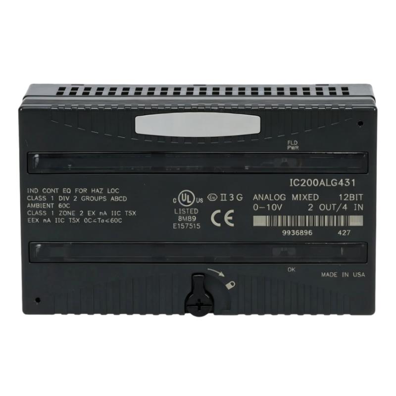
Product Overview
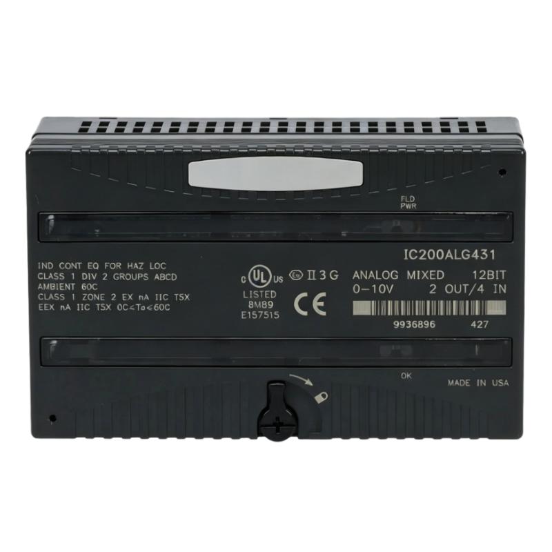
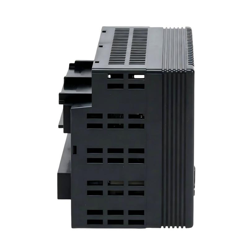
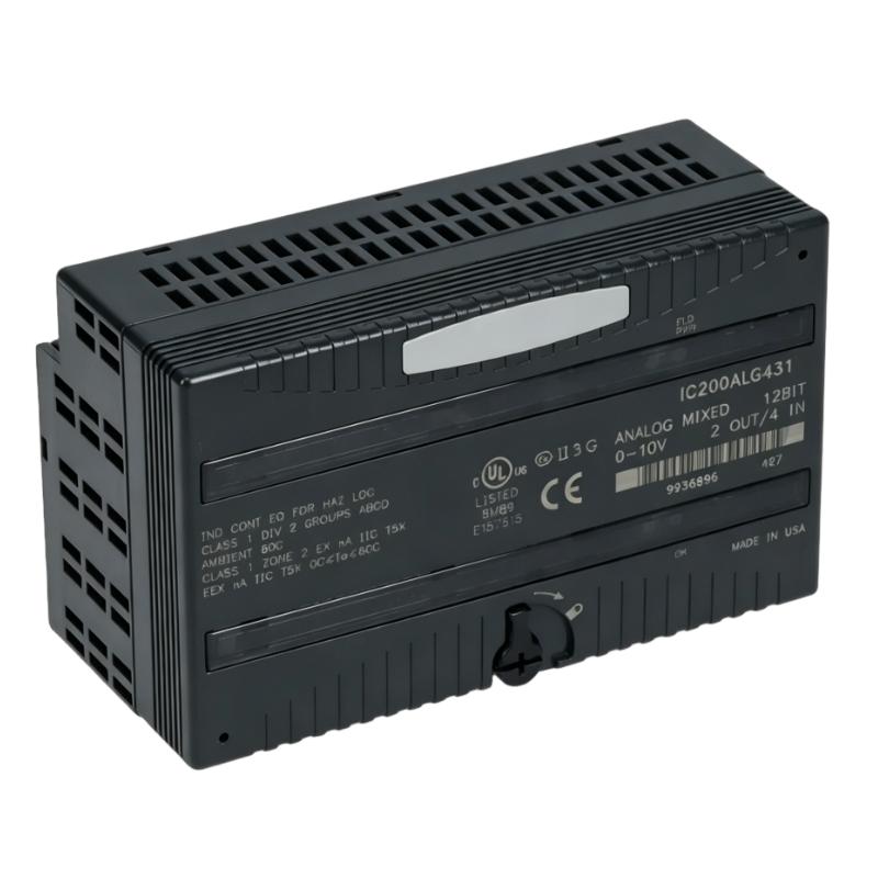
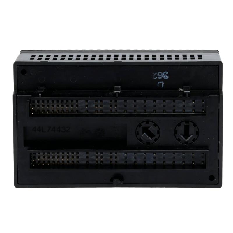
The GE IC200ALG431F VersaMax Analog Mixed Module combines analog input and output functions within a single VersaMax I/O module. It is suited to control panels where both process measurement and analog control signals are required but separate input and output modules would add unnecessary I/O hardware.
In a typical VersaMax installation, the module collects analog signals from field instruments and passes the acquired values to the PLC controller. At the same time, its analog output channels can send control signals to compatible field devices such as valves, actuators, drives, or other analog-controlled equipment.
This mixed I/O arrangement is useful on compact machines, process skids, packaging equipment, utility systems, and distributed control panels. Engineers can use the same module for monitoring a process variable while also generating an analog command based on the PLC control program.
During troubleshooting, the input and output sides should be checked separately. An incorrect process reading may originate from the transmitter or input wiring, while an abnormal output may be associated with the control program, output wiring, or the connected actuator.
Technical Specifications
| Parameter | Specification |
|---|---|
| Model | IC200ALG431F |
| Product Family | GE VersaMax |
| Product Type | Analog Mixed Module |
| Primary Function | Analog signal input and output |
| System Role | Analog I/O interface |
| Application | Industrial automation and process control |
| Dimensions | 110 × 66.8 × 50 mm |
| Weight | 0.33 kg |
Product Features
- Combines analog input and analog output functions in one module
- Suitable for VersaMax PLC-based control systems
- Handles both process measurement and analog control signals
- Reduces the need for separate analog input and output hardware in compact installations
- Suitable for machine and process automation applications
- Supports bidirectional analog signal interaction between the PLC and field equipment
- Practical for distributed I/O and control-panel installations
- Suitable for maintenance and replacement of existing VersaMax systems
Working Principle
The IC200ALG431F handles two directions of analog signal flow. Input channels receive measurement signals from field instruments and make the corresponding process data available to the VersaMax controller. Output channels work in the opposite direction, receiving commands from the controller and sending analog control signals to external equipment.
Field Transmitters → IC200ALG431F → VersaMax Controller → Control Logic
VersaMax Controller → IC200ALG431F → Analog Actuators / Field Equipment
For example, a transmitter can send a process measurement to the module while the PLC calculates a control response and sends the resulting analog command through the output section. This allows measurement and control functions to be handled within the same I/O location.
Role in a GE VersaMax Control Architecture
The IC200ALG431F serves as a combined analog interface between the VersaMax controller and field equipment. Its input channels bring continuous process information into the control system, while its output channels transfer calculated control commands back to compatible devices.
Field Instruments → IC200ALG431F → VersaMax Controller → IC200ALG431F → Control Devices
| System Element | Function |
|---|---|
| Analog Transmitters | Measure process variables and generate analog input signals |
| IC200ALG431F | Handles analog input and output signal interfacing |
| VersaMax Backplane | Provides the module connection within the I/O structure |
| VersaMax Controller | Processes input data and executes control logic |
| HMI / SCADA | Displays process values and operating information |
| Analog Actuators | Receive analog commands from the control system |
Industrial Applications
| Application | Typical Use |
|---|---|
| Machine Automation | Analog measurement and actuator control |
| Process Automation | Monitoring and regulating continuous process variables |
| Packaging Equipment | Sensor feedback and analog device control |
| Manufacturing Lines | Process measurement and proportional control |
| Water Treatment | Monitoring process parameters and controlling equipment |
| Industrial Utilities | Analog monitoring and control of pumps and related equipment |
Installation and Maintenance
- Confirm that the IC200ALG431F is suitable for the existing VersaMax I/O configuration.
- Verify the required analog input and output signal types before wiring.
- Check terminal assignments against the system wiring documentation.
- Inspect field transmitters and sensors connected to the input channels.
- Verify that input signals reach the module correctly.
- Check the output wiring separately from the input wiring during commissioning.
- Confirm that connected actuators accept the expected analog control signal.
- Compare actual field measurements with the values reported by the PLC.
- If an output is incorrect, check the PLC control logic before replacing the module.
- Inspect terminals for loose connections, corrosion, or damaged conductors.
- When replacing the module, document the existing wiring and channel configuration before removal.
- After replacement, test both analog input acquisition and analog output response before returning the equipment to normal operation.
Related Components
| Component | Function |
|---|---|
| GE VersaMax Controller | Executes control logic and processes analog I/O data |
| VersaMax I/O Interface | Connects I/O modules to the controller architecture |
| Analog Transmitter | Provides continuous process measurement signals |
| Analog Actuator | Receives analog control commands |
| Terminal Block | Provides field wiring termination |
| HMI | Displays analog process values and control status |
| SCADA System | Supervises process information and equipment operation |
| VersaMax Digital I/O Modules | Handles discrete signals within the same control system |
Recommended Related Models
| Model / Product Family | Product Type | Typical Application |
|---|---|---|
| GE IC200ALG431F | Analog Mixed Module | Combined analog input and output |
| GE VersaMax Analog Input Modules | Analog Input | Process measurement acquisition |
| GE VersaMax Analog Output Modules | Analog Output | Analog actuator control |
| GE VersaMax Analog Mixed Modules | Mixed Analog I/O | Combined measurement and control |
| GE VersaMax Digital Input Modules | Digital Input | Discrete signal acquisition |
| GE VersaMax Digital Output Modules | Digital Output | Discrete equipment control |
| GE VersaMax CPU Modules | PLC Controller | Program execution and system control |
| GE VersaMax Power Supply Modules | Power Supply | I/O system power distribution |
Key Advantages
- Combines analog input and output functions in a single I/O module
- Suitable for compact VersaMax control architectures
- Supports both process measurement and analog control
- Reduces separate module requirements for mixed analog applications
- Practical for machine, process, and utility control systems
- Simplifies analog signal integration within VersaMax installations
Technical FAQs
When is an analog mixed module preferable to separate analog input and output modules?
It is useful when the application requires both measurement and analog control but does not justify installing separate input and output modules. A mixed module can simplify the I/O arrangement in compact control panels.
How should an abnormal analog input be distinguished from an output problem?
First determine whether the issue affects the signal entering the PLC or the command leaving the PLC. For an input problem, check the transmitter and field wiring. For an output problem, check the PLC command, output wiring, and connected actuator.
Can the IC200ALG431F be used for closed-loop control applications?
Yes, where the connected signal types and system configuration are appropriate. A typical loop can acquire a process measurement through an analog input and use the PLC control program to calculate an analog output command for the associated control device.
What should be checked after replacing the IC200ALG431F?
Verify the module installation, field wiring, channel assignments, input readings, and output behavior. Both directions of analog signal flow should be tested because a mixed module serves measurement and control functions within the same I/O unit.