

ProductPRODUCT
Featured products

Contact Us
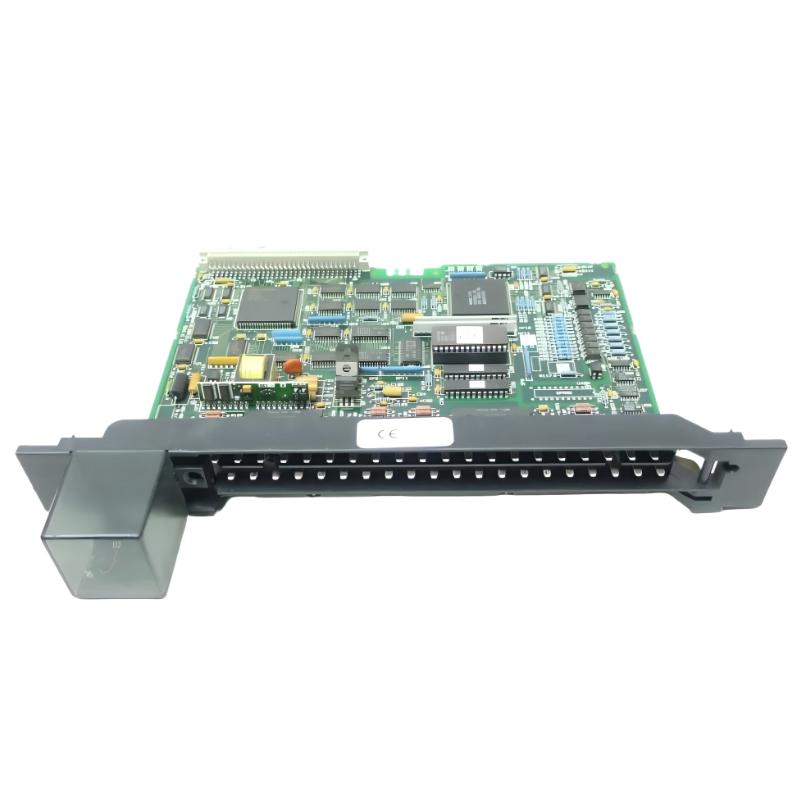
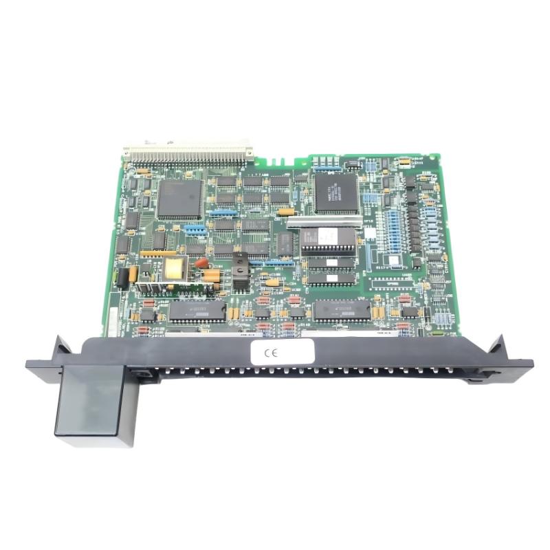
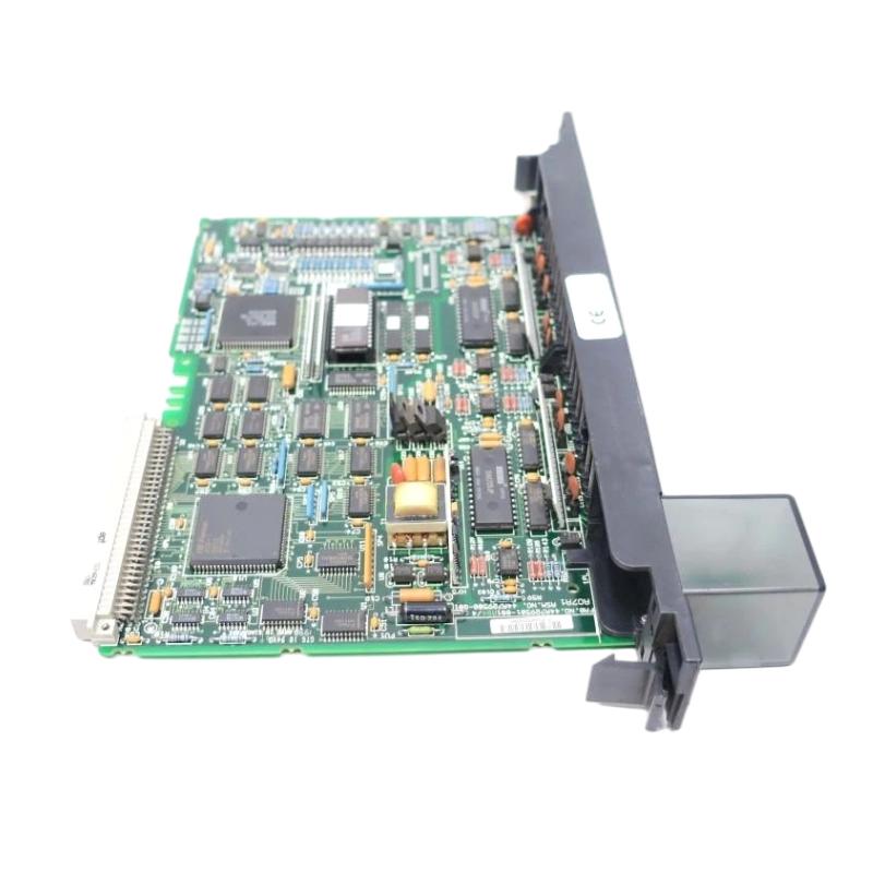
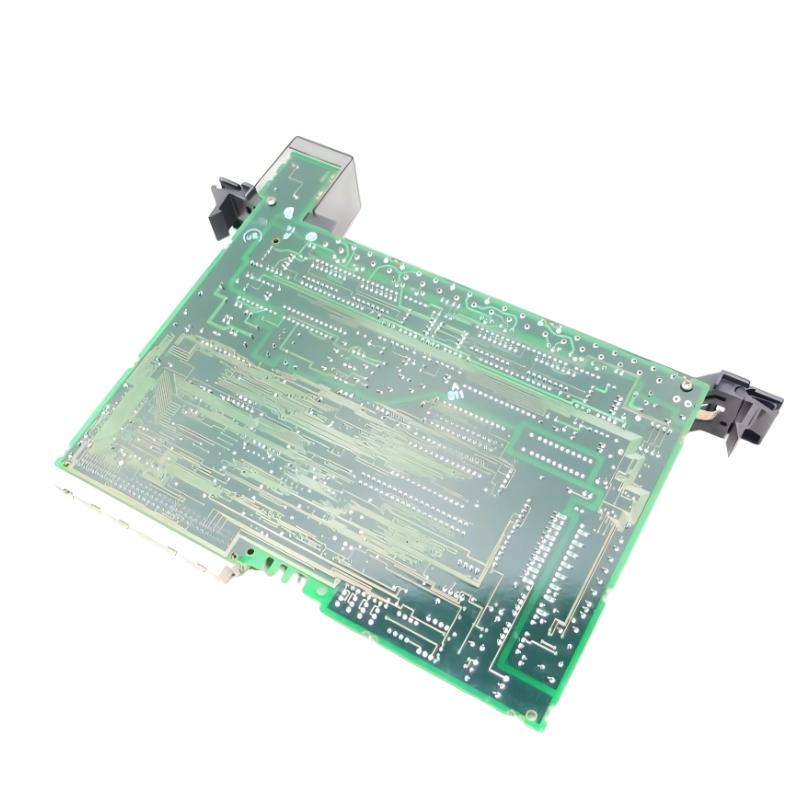
- GE
- IC697ALG234
- I/O Module
- USA
- 138 × 67 × 25 mm
- 0.33 kg
- Xiamen, China
- New & In Stock
- T/T, PayPal, Western Union
- 1 Year
- 1-3 Working Days
- DHL, UPS, TNT, FedEx and EMS.
- 24-Hour Service
- COO
- 53
Our advantage

Global Logistics
We have a 10-year logistics and express cooperation agreement, so our products can be shipped to any place in the world.

Brand new and original
Our products are imported in bulk from the place of origin. Because of the cooperative relationship, our products are all original and 100% new.

24-hour service
We provide 7*24 hours service to our customers. We will be there whenever you need us.

Price advantage
All our products are priced very favorably because we have our own warehouse and supply.
| Company Information | |||
| [email protected] | |||
| Mobile | +8615980777398 | ||
| +8615980777398 | |||
| 15980777398 |
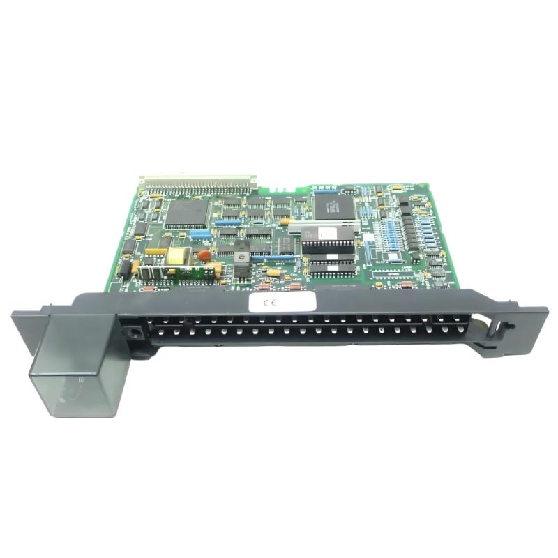
Product Overview
The GE IC697ALG234 I/O Module is an industrial automation module designed for integration into compatible GE PLC control systems. As part of a modular control architecture, an I/O module provides the interface between the controller and field-level equipment, allowing signals from industrial devices to enter the PLC system and control commands to reach connected equipment.
I/O modules are fundamental to PLC-based automation because the CPU itself does not normally connect directly to every field instrument. Instead, the I/O architecture separates controller processing from field signal interfacing. This makes it possible to organize large control systems around dedicated racks, signal modules, communication interfaces, and application-specific hardware.
The supplied physical specifications for the GE IC697ALG234 are 138 × 67 × 25 mm, with a listed weight of 0.33 kg.
Because the exact electrical configuration of an I/O module depends on the host system and application, technicians should verify the applicable signal characteristics, terminal assignments, rack position, and configuration before installation.
Product Identification
| Parameter | Specification |
|---|---|
| Manufacturer | GE |
| Model | IC697ALG234 |
| Product Type | I/O Module |
| Product Category | PLC I/O Interface |
| Primary Function | Field Signal Interface |
| Application | Industrial Automation |
| Dimensions | 138 × 67 × 25 mm |
| Weight | 0.33 kg |
| Installation | Compatible GE PLC Rack |
| System Role | Controller-to-Field Interface |
| Maintenance | Module, Wiring, Configuration, and Diagnostic Inspection |
Technical Specifications
| Technical Item | Specification |
|---|---|
| Brand | GE |
| Model Number | IC697ALG234 |
| Product Type | I/O Module |
| Main Function | Industrial I/O Signal Interface |
| Dimensions | 138 × 67 × 25 mm |
| Weight | 0.33 kg |
| Installation Type | PLC Rack Module |
| Application | Industrial Control |
| System Role | Field I/O Interface |
| Signal Processing | Application-Dependent |
| Maintenance Requirement | Periodic Inspection |
| Primary Service Areas | Module, Field Wiring, Rack, Configuration |
The dimensions and weight above are based on the product information supplied for this model. The exact electrical I/O characteristics, channel assignments, and terminal specifications should be confirmed against the applicable system documentation before wiring.
What Is the GE IC697ALG234?
The GE IC697ALG234 serves as an I/O interface within a compatible GE industrial control architecture.
The general relationship between the PLC and field devices is:
Field Devices
↓
IC697ALG234
↓
PLC Backplane
↓
PLC CPU
↓
Control Logic
↓
Output / Control Devices
Depending on the system architecture, I/O modules can provide the controller with information from field devices or transfer controller commands toward external equipment.
This modular arrangement makes it easier to organize control-system wiring and distribute field interfaces throughout an industrial installation.
Role of an I/O Module in PLC Automation
A PLC control system can generally be divided into several functional layers:
Field Layer
Includes:
- Sensors
- Switches
- Transmitters
- Valves
- Contactors
- Actuators
- Motors
- Other process equipment
I/O Layer
Provides the electrical interface between field equipment and the controller.
Controller Layer
The PLC CPU executes the application program and makes control decisions.
Supervisory Layer
HMIs, engineering workstations, and monitoring systems can display process information and provide operator interaction.
The IC697ALG234 belongs to the I/O layer and therefore plays an important role in connecting field equipment with controller logic.
Main Functions
Field Signal Interface
The module provides an organized connection between external equipment and the PLC system.
Signal Transfer
Field information can be transferred toward the controller, while control information can be transferred toward field devices according to the module’s application.
Modular System Expansion
I/O modules allow a PLC system to be expanded according to the number and type of field signals required.
Control-System Integration
The module works as part of the larger PLC architecture rather than as an independent controller.
Diagnostic Support
Correctly configured I/O modules can help technicians identify field or system conditions through controller diagnostics and application monitoring.
Typical Industrial Applications
Manufacturing Equipment
I/O modules are widely used in:
- Assembly machines
- Production lines
- Packaging equipment
- Material-handling systems
- Automated machinery
Process Automation
Potential applications include:
- Pump control
- Valve control
- Process monitoring
- Equipment status
- Interlock systems
Water and Wastewater
I/O interfaces can connect:
- Pumps
- Valves
- Level instruments
- Pressure instruments
- Equipment status signals
Material Handling
Applications can include:
- Conveyor systems
- Motor control
- Position detection
- Equipment interlocks
- Machine sequencing
Industrial Utility Systems
I/O modules can form part of systems controlling:
- Fans
- Pumps
- Compressors
- Auxiliary equipment
- Plant services
Installation Guide
1. Verify the Host System
Before installing the IC697ALG234, confirm:
- PLC platform
- Rack type
- Rack position
- Module compatibility
- Field-device requirements
- I/O configuration
- Wiring requirements
Do not assume compatibility based only on the module’s physical dimensions.
2. Confirm Module Identification
Verify the module marking:
GE IC697ALG234
Inspect the module for:
- Cracked housing
- Bent contacts
- Damaged connector
- Corrosion
- Contamination
- Signs of overheating
The supplied dimensions are:
138 × 67 × 25 mm
The supplied weight is:
0.33 kg
3. Back Up the PLC Application
Before making hardware changes:
- Back up the PLC program.
- Record the existing rack configuration.
- Document module positions.
- Save current configuration data.
- Record any existing diagnostic conditions.
This allows the original system state to be restored if required.
4. Shut Down the Control System
Before installing the module:
- Stop the controlled process.
- Shut down the PLC according to site procedures.
- Isolate applicable power.
- Apply lockout/tagout requirements.
- Verify that the cabinet is safe to access.
5. Inspect the Rack and Backplane
Check the intended rack position for:
- Bent contacts
- Damaged connectors
- Dust
- Foreign objects
- Corrosion
- Mechanical damage
A poor backplane connection can cause intermittent I/O communication problems.
6. Install the Module
Align the IC697ALG234 with the correct rack position.
Insert the module evenly until it is fully seated.
Do not force the module.
If the module does not fit normally, inspect the rack connector and module contacts before proceeding.
7. Secure the Module
Confirm:
- Module is fully seated
- Retaining hardware is secure
- Connector is properly engaged
- Adjacent modules remain correctly positioned
- Module is mechanically stable
8. Connect Field Wiring
Before connecting field devices:
- Identify each field connection.
- Verify the intended signal path.
- Confirm terminal assignments.
- Check conductor condition.
- Tighten connections according to applicable installation procedures.
- Label field wiring clearly.
Keep control wiring organized and separated from high-energy circuits where appropriate.
9. Check Grounding
Verify the cabinet and field-device grounding arrangement.
Inspect:
- Cabinet grounding
- Signal reference
- Shielding
- Field-device grounding
- Cable routing
Incorrect grounding can result in unstable signals or unexpected I/O behavior.
10. Configure the Module
The PLC hardware configuration should match the actual rack installation.
Verify:
- Module identification
- Rack position
- I/O assignment
- Channel configuration
- Application mapping
- Diagnostic settings where applicable
Incorrect configuration can cause the PLC to interpret the module incorrectly.
11. Restore Power
After installation:
- Inspect all connections.
- Confirm that no tools remain in the cabinet.
- Restore power.
- Start the PLC.
- Observe controller and module diagnostics.
12. Test the I/O
Perform controlled functional testing.
For input signals:
Field Device
→ I/O Module
→ PLC Input
→ Application Logic
For output signals:
PLC Logic
→ I/O Module
→ Field Device
Verify that the observed field behavior corresponds to the PLC command or input condition.
Commissioning Checklist
| Item | Verification |
|---|---|
| IC697ALG234 Identified | Confirmed |
| Host PLC Verified | Confirmed |
| Rack Position Confirmed | Confirmed |
| Application Backed Up | Confirmed |
| Power Isolated | Confirmed |
| Module Inspected | Confirmed |
| Backplane Inspected | Confirmed |
| Field Wiring Identified | Confirmed |
| Terminal Connections Checked | Confirmed |
| Grounding Verified | Confirmed |
| Configuration Verified | Confirmed |
| PLC Restarted | Confirmed |
| Input Signals Tested | Confirmed |
| Output Functions Tested | Confirmed |
| Diagnostics Checked | Confirmed |
Troubleshooting Guide
Module Is Not Recognized
Possible causes include:
- Poor module seating
- Incorrect rack position
- Backplane connection problem
- Hardware configuration mismatch
- Power problem
- Module hardware failure
Start with the physical installation before investigating more complex software issues.
I/O Signals Are Not Updating
If input information does not change in the PLC, inspect:
- Field device
- Field wiring
- Terminal connections
- Module seating
- Channel configuration
- PLC application logic
Determine whether the problem exists at the field device or only inside the controller.
Output Does Not Operate
If the PLC commands an output but the field device does not respond, check:
- PLC output status.
- I/O module status.
- Terminal wiring.
- Field-device power.
- Protective devices.
- Actuator condition.
- Application interlocks.
A module can correctly produce an output command while the external actuator remains inactive because of a field-side problem.
Intermittent I/O Operation
Possible causes include:
- Loose wiring
- Poor connector contact
- Vibration
- Electrical interference
- Power instability
- Temperature fluctuations
- Damaged field cable
Monitor the system during normal operating conditions to reproduce the fault.
Several Channels Fail Simultaneously
When multiple channels fail at the same time, investigate common causes first.
Check:
- Module power
- Rack/backplane connection
- Common field supply
- Grounding
- Configuration
- Shared wiring
- Controller status
A simultaneous multi-channel failure is often associated with a common system element.
I/O Values Are Incorrect
Possible causes include:
- Incorrect field wiring
- Incorrect channel assignment
- Incorrect configuration
- Faulty field device
- Application logic problem
- Electrical interference
Trace the signal from the field device to the PLC rather than replacing the module immediately.
I/O Status Changes Unexpectedly
Unexpected status changes can be caused by:
- Electrical noise
- Loose connections
- Faulty sensors
- Contact bounce
- Poor grounding
- Damaged field wiring
- Incorrect PLC logic
For critical signals, verify the physical field condition independently.
Module Causes PLC Faults
If installing the module results in controller diagnostics, check:
- Module identification
- Rack location
- Hardware configuration
- Backplane condition
- Module condition
- System power
Compare the system behavior before and after installation to isolate the cause.
Communication or Backplane Problems
If the controller intermittently loses the module, inspect:
- Module seating
- Rack connector
- Backplane condition
- Mechanical vibration
- Cabinet temperature
- System power
Intermittent backplane connections can produce symptoms that appear to be software faults.
Preventive Maintenance
Monthly Inspection
Check:
- Module status
- I/O operation
- Cabinet temperature
- Visible contamination
- Field-device status
Quarterly Inspection
Inspect:
- Module seating
- Rack connection
- Terminal connections
- Field wiring
- Grounding
- Cable routing
Annual Maintenance
Perform:
- Detailed module inspection
- I/O functional testing
- Configuration backup
- Wiring inspection
- Cabinet thermal inspection
- Diagnostic review
The inspection interval should be adjusted according to the plant environment.
I/O Troubleshooting Method
A structured troubleshooting procedure can significantly reduce downtime.
Step 1 — Identify the Fault
Determine whether the problem affects:
- One channel
- Multiple channels
- The entire module
- The complete rack
Step 2 — Check the Field Device
Verify the actual physical state of the connected equipment.
Step 3 — Check Wiring
Inspect terminals, conductors, connectors, and common connections.
Step 4 — Check the Module
Review module status and controller diagnostics.
Step 5 — Check Configuration
Verify rack position, I/O assignment, and application mapping.
Step 6 — Check PLC Logic
Confirm that the application program correctly interprets the I/O state.
This sequence helps identify whether the fault is located in the field, wiring, module, rack, configuration, or application.
Replacement Considerations
Before replacing the IC697ALG234, verify:
| Check Item | Purpose |
|---|---|
| Model Number | Confirms correct replacement |
| PLC Platform | Ensures compatibility |
| Rack Position | Confirms physical installation |
| I/O Configuration | Prevents mapping errors |
| Field Wiring | Ensures correct connections |
| Power | Confirms proper system operation |
| Application Logic | Prevents software-related replacement |
| Environmental Conditions | Supports reliable operation |
Compatible System Components
The IC697ALG234 should be evaluated as part of the complete PLC architecture.
| Component | Function |
|---|---|
| PLC CPU | Main Control Processing |
| I/O Module | Field Signal Interface |
| Rack / Backplane | Module Interconnection |
| Power Supply | System Power |
| Field Sensors | Process Measurement |
| Actuators | Physical Control |
| Communication Modules | Network Data Exchange |
| Programming Workstation | Configuration and Diagnostics |
| Cabinet Cooling | Thermal Management |
The exact combination should be verified for the intended GE control-system installation.
Key Advantages
Modular Field Interface
The IC697ALG234 provides an organized interface between the PLC and connected field equipment.
PLC System Integration
The module can be incorporated into a modular control architecture where controller processing and field interfacing are separated.
Compact Construction
The supplied dimensions are 138 × 67 × 25 mm, with a listed weight of 0.33 kg.
Simplified Maintenance
A modular I/O architecture allows technicians to isolate problems by examining the field device, wiring, module, rack, and PLC configuration independently.
Industrial Automation Application
The module is suited to PLC-based industrial control architectures where reliable field-level signal interfacing is required.
Frequently Asked Questions
What is the GE IC697ALG234?
The GE IC697ALG234 is an I/O Module intended for integration into a compatible GE PLC control system.
What are its dimensions?
The supplied dimensions are:
138 × 67 × 25 mm
What is its weight?
The listed weight is:
0.33 kg
What is the purpose of an I/O module?
An I/O module provides the electrical interface between PLC logic and field devices such as sensors, switches, actuators, and other industrial equipment.
Why is the module not recognized by the PLC?
Possible causes include incorrect rack position, poor module seating, backplane problems, configuration mismatch, power issues, or module failure.
Why is an input signal not changing?
Check the field device, wiring, terminal connections, module seating, channel configuration, and PLC application logic.
Why does an output command not activate the equipment?
Check the PLC output state, module status, field wiring, device power, protective equipment, actuator, and application interlocks.
Why are several channels failing at once?
Investigate common factors such as module power, rack connection, shared field supply, grounding, configuration, and common wiring.
Can the IC697ALG234 be replaced while powered?
Unless the specific host system explicitly supports live replacement, power should be isolated before removing or installing the module.
Installation Checklist
| Item | Status |
|---|---|
| Correct IC697ALG234 Identified | ✓ |
| Host PLC Verified | ✓ |
| Rack Position Confirmed | ✓ |
| Application Backed Up | ✓ |
| Power Isolated | ✓ |
| Module Inspected | ✓ |
| Backplane Inspected | ✓ |
| Field Wiring Identified | ✓ |
| Terminal Connections Checked | ✓ |
| Grounding Verified | ✓ |
| Configuration Verified | ✓ |
| PLC Restarted | ✓ |
| I/O Signals Tested | ✓ |
| Field Devices Tested | ✓ |
| Diagnostics Checked | ✓ |
Conclusion
The GE IC697ALG234 I/O Module is a compact PLC interface component designed to connect field-level equipment with a compatible GE industrial automation system. With supplied dimensions of 138 × 67 × 25 mm and a listed weight of 0.33 kg, it can form part of a modular control architecture in which field signals are separated from the main PLC processing functions.
Successful installation requires verification of the host PLC architecture, rack position, backplane condition, field wiring, grounding, configuration, and application logic. Functional testing should be performed after installation to confirm that input signals reach the controller correctly and that output commands produce the intended field response.
For troubleshooting, technicians should isolate the fault systematically by checking the field device, wiring, I/O module, rack connection, configuration, and PLC program. This approach helps prevent unnecessary replacement of functioning hardware and makes it easier to identify the actual source of an I/O problem.