

ProductPRODUCT
Featured products


Contact Us
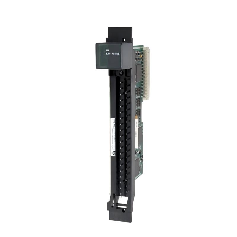
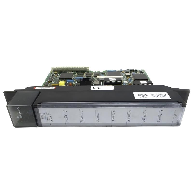
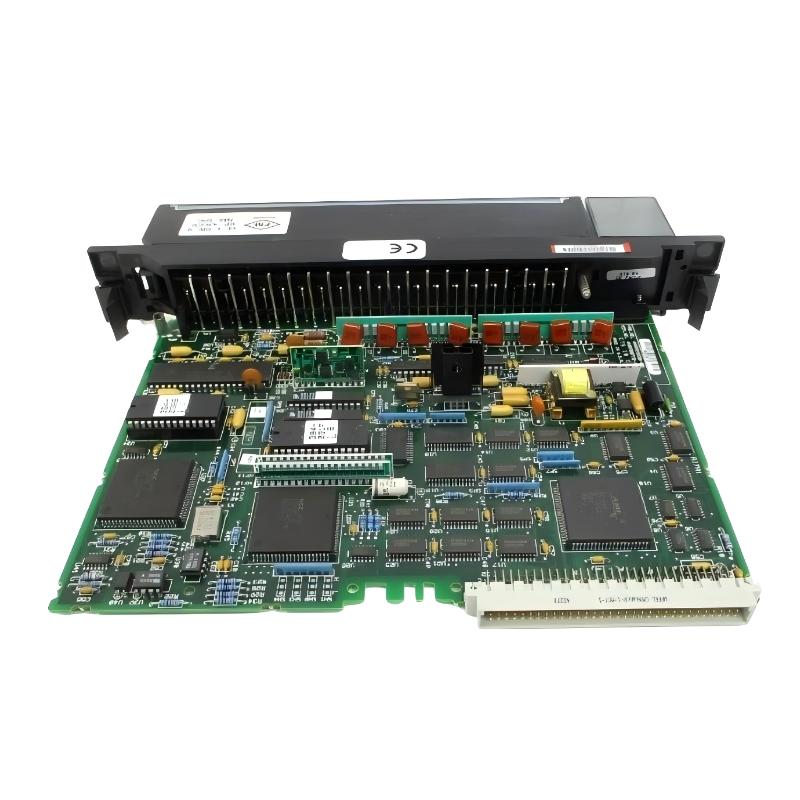
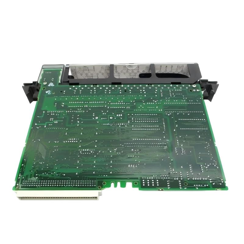
- GE
- IC697ALG230J
- Analog Input Basic Converter Module
- USA
- 138 × 70 × 25 mm
- 0.8 kg
- Xiamen, China
- New & In Stock
- T/T, PayPal, Western Union
- 1 Year
- 1-3 Working Days
- DHL, UPS, TNT, FedEx and EMS.
- 24-Hour Service
- COO
- 58
Our advantage

Global Logistics
We have a 10-year logistics and express cooperation agreement, so our products can be shipped to any place in the world.

Brand new and original
Our products are imported in bulk from the place of origin. Because of the cooperative relationship, our products are all original and 100% new.

24-hour service
We provide 7*24 hours service to our customers. We will be there whenever you need us.

Price advantage
All our products are priced very favorably because we have our own warehouse and supply.
| Company Information | |||
| [email protected] | |||
| Mobile | +8615980777398 | ||
| +8615980777398 | |||
| 15980777398 |
Product Overview
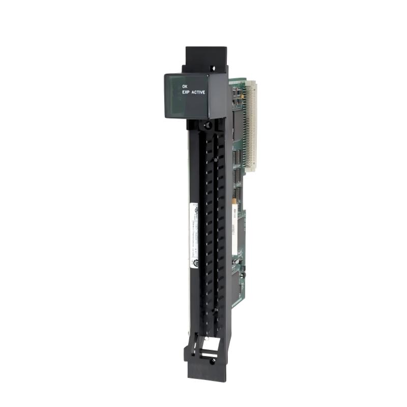
The GE IC697ALG230J Analog Input Basic Converter Module is an industrial automation module used to interface analog field signals with compatible GE PLC control systems. It is intended for applications where continuously varying process information must be acquired and processed by a programmable controller.
Analog input modules form the connection between field instrumentation and PLC logic. Sensors and transmitters can generate electrical signals representing process conditions such as temperature, pressure, flow, level, position, or other continuously changing variables. The IC697ALG230J provides the analog input conversion interface that allows this information to become part of the PLC control architecture.
The supplied physical specifications for the GE IC697ALG230J are 138 × 70 × 25 mm, with a listed weight of 0.8 kg.
For reliable operation, installation should include verification of the host rack, field signal, wiring, grounding, shielding, module configuration, and PLC application scaling.
Product Identification
| Parameter | Specification |
|---|---|
| Manufacturer | GE |
| Model | IC697ALG230J |
| Product Type | Analog Input Basic Converter Module |
| Product Category | Analog Input Module |
| Primary Function | Analog Signal Acquisition and Conversion |
| Application | Industrial Automation |
| Dimensions | 138 × 70 × 25 mm |
| Weight | 0.8 kg |
| Installation | Compatible GE PLC Rack |
| Signal Interface | Analog Field Signals |
| System Role | Field-to-PLC Signal Interface |
| Maintenance | Module, Wiring, Signal, and Configuration Inspection |
Technical Specifications
| Technical Item | Specification |
|---|---|
| Brand | GE |
| Model Number | IC697ALG230J |
| Product Type | Analog Input Basic Converter Module |
| Main Function | Analog Input Signal Conversion |
| Dimensions | 138 × 70 × 25 mm |
| Weight | 0.8 kg |
| Installation Type | PLC Rack Module |
| Application | Industrial Control |
| Signal Processing | Analog Signal Acquisition |
| System Role | Analog Field Interface |
| Maintenance Requirement | Periodic Inspection |
| Primary Service Areas | Module, Field Wiring, Configuration, Signal Quality |
Dimensions and weight are based on the product information supplied for this model. Exact electrical characteristics and channel specifications should be confirmed against the applicable equipment documentation before field wiring.
Understanding the GE IC697ALG230J
The GE IC697ALG230J is used within a PLC-based automation architecture to receive analog information from field equipment.
A simplified signal path is:
Process Variable
→ Sensor
→ Transmitter
→ Analog Field Signal
→ IC697ALG230J
→ PLC Data
→ Control Program
→ Control Output
This arrangement allows a PLC to make control decisions based on continuously changing measurements.
For example, a pressure transmitter may send a variable electrical signal as pipeline pressure changes. The analog input system receives that signal, converts it into usable controller data, and allows the PLC application to compare the measurement with configured limits or control targets.
Core Functions
Analog Input Acquisition
The module receives analog signals from compatible field instrumentation.
Signal Conversion
The analog signal is converted into controller-readable information.
Process Monitoring
Acquired values can be used for operator monitoring, trending, alarms, and process calculations.
Feedback Control
Analog measurements can provide feedback for control loops implemented in the PLC application.
Field-to-Controller Interface
The module provides an important interface between physical process equipment and digital PLC logic.
Position in an Automation System
The IC697ALG230J does not operate as an isolated measurement device. It forms part of a complete control architecture.
A typical system may contain:
Field Sensor
↓
Transmitter
↓
Analog Input Module
↓
PLC CPU
↓
Control Logic
↓
Output Module
↓
Actuator
↓
Industrial Process
This architecture is common in machinery, process control, utilities, and plant automation.
Typical Applications
Manufacturing Automation
Analog measurements can be used for:
- Machine temperature
- Pressure monitoring
- Position feedback
- Force measurement
- Production-process monitoring
Process Control
Typical applications include:
- Flow measurement
- Tank-level monitoring
- Pressure control
- Temperature control
- Process feedback
Pumping Systems
Analog instrumentation can provide:
- Suction pressure
- Discharge pressure
- Flow feedback
- Tank level
- Equipment operating data
Water Treatment
Possible measurements include:
- Tank level
- Flow
- Pressure
- Process variables
- Pump conditions
Industrial Utility Systems
Analog inputs can support:
- Equipment monitoring
- Auxiliary control
- Plant instrumentation
- Environmental measurements
- System diagnostics
Analog Measurement Chain
Reliable analog measurement depends on the complete signal chain.
Field Instrument
Measures the physical variable.
Transmitter
Converts the measurement into an electrical signal.
Field Cable
Transfers the signal to the control cabinet.
IC697ALG230J
Receives and converts the analog input.
PLC CPU
Processes the converted value.
Application Software
Uses the value for monitoring, control, alarms, or calculations.
A fault anywhere in this chain can result in an incorrect PLC reading.
Installation Guide
1. Confirm the Control-System Architecture
Before installation, verify:
- PLC platform
- Rack type
- Rack position
- Module compatibility
- Field instrument type
- Analog signal type
- Wiring arrangement
- Application requirements
Physical fit alone is not sufficient to establish system compatibility.
2. Verify the Module
Confirm:
GE IC697ALG230J
Inspect the housing and connector for:
- Cracks
- Bent contacts
- Physical deformation
- Contamination
- Corrosion
- Signs of overheating
The supplied dimensions are:
138 × 70 × 25 mm
The supplied weight is:
0.8 kg
3. Back Up the Existing PLC Program
Before modifying the hardware:
- Back up the PLC application.
- Save the current hardware configuration.
- Record existing module locations.
- Document important process values.
- Save configuration parameters.
This provides a recovery point if commissioning changes produce unexpected behavior.
4. Shut Down the System
Before installation:
- Stop the controlled process.
- Shut down the PLC.
- Isolate applicable electrical power.
- Apply lockout/tagout procedures where required.
- Confirm that the cabinet is safe to access.
5. Inspect the Rack
Inspect the target rack position for:
- Bent contacts
- Damaged connectors
- Dust
- Foreign objects
- Corrosion
- Mechanical damage
A poor rack connection can cause intermittent module faults.
6. Install the Module
Align the IC697ALG230J with the intended rack position.
Insert the module evenly until fully seated.
Do not use excessive force.
If the module does not seat normally, stop and inspect both the module and rack interface.
7. Secure the Module
Verify:
- Module seating
- Retaining hardware
- Connector engagement
- Adjacent module clearance
- Mechanical stability
8. Prepare Field Wiring
Before connecting the analog instrument:
- Identify the field device.
- Confirm its signal type.
- Verify polarity.
- Check signal reference requirements.
- Label the conductors.
- Inspect terminal connections.
- Keep analog wiring separated from high-power conductors where practical.
9. Check Shielding and Grounding
Analog signals can be sensitive to electrical noise.
Inspect:
- Cable shield
- Shield termination
- Signal reference
- Cabinet grounding
- Instrument grounding
- Cable routing
Improper grounding can result in measurement instability or offsets.
10. Configure the Input
Configure the module and PLC application according to the actual field instrumentation.
Typical considerations include:
- Channel assignment
- Input type
- Signal range
- Scaling
- Engineering units
- Alarm thresholds
- Filtering
- Data handling
The configuration must correspond to the connected field device.
11. Restore Power
After checking all wiring:
- Inspect the rack.
- Confirm no tools remain inside the cabinet.
- Restore power.
- Start the PLC.
- Observe system diagnostics.
12. Verify the Input
Use a known input condition and compare:
Field Signal
→ Module Input
→ PLC Raw Value
→ Engineering Value
The result should correspond to the expected process measurement.
Commissioning Checklist
| Item | Verification |
|---|---|
| IC697ALG230J Identified | Confirmed |
| PLC Platform Verified | Confirmed |
| Rack Position Verified | Confirmed |
| PLC Program Backed Up | Confirmed |
| Power Isolated | Confirmed |
| Module Inspected | Confirmed |
| Rack Interface Inspected | Confirmed |
| Field Instrument Identified | Confirmed |
| Signal Wiring Verified | Confirmed |
| Shielding Checked | Confirmed |
| Grounding Checked | Confirmed |
| Configuration Verified | Confirmed |
| PLC Restarted | Confirmed |
| Analog Input Tested | Confirmed |
| Diagnostics Checked | Confirmed |
Troubleshooting Guide
Analog Channel Reads Zero
Possible causes include:
- Field transmitter not powered
- Broken signal wire
- Incorrect polarity
- Incorrect signal reference
- Configuration error
- Sensor failure
- Module connection problem
Check the field signal independently before replacing the module.
Analog Value Is Too High
Potential causes include:
- Incorrect scaling
- Incorrect signal-range configuration
- Sensor calibration problem
- Wiring error
- Electrical interference
- Incorrect engineering-unit conversion
Compare the actual field signal with the value reported by the PLC.
Analog Value Is Too Low
Inspect:
- Sensor output
- Transmitter power
- Cable continuity
- Terminal connections
- Signal reference
- Configuration
- Scaling
A low PLC value does not automatically indicate module failure.
Analog Value Is Unstable
Possible causes include:
- Electrical noise
- Poor shielding
- Ground-loop problems
- Loose terminals
- Damaged cable
- Unstable transmitter
- Incorrect configuration
Check whether the signal becomes unstable when motors, drives, contactors, or other switching equipment operate.
Analog Value Does Not Change
If the process changes but the PLC value remains fixed, investigate:
- Sensor output
- Transmitter
- Wiring
- Input configuration
- Channel assignment
- PLC logic
- Module hardware
Compare the field signal directly with the PLC input value.
Module Is Not Recognized
Possible causes include:
- Poor module seating
- Incorrect rack position
- Backplane problem
- Configuration mismatch
- Power problem
- Module hardware failure
Start with physical installation and controller diagnostics.
Multiple Channels Are Incorrect
When several channels show similar errors, investigate common factors:
- Module power
- Rack connection
- Signal reference
- Grounding
- Shielding
- Configuration
- Environmental noise
Multiple simultaneous faults often point toward a common connection or configuration problem.
Excessive Analog Noise
Inspect:
- Analog cable routing.
- Cable shielding.
- Grounding.
- Variable-frequency drives.
- Motor cables.
- Contactors.
- Sensor power supply.
- Terminal tightness.
Avoid running sensitive analog cables alongside high-current switching conductors whenever practical.
Analog Fault Appears After Maintenance
If the input worked correctly before cabinet maintenance, check:
- Module seating
- Terminal connections
- Field wiring
- Backplane interface
- Shield termination
- Configuration changes
Maintenance activity can unintentionally disturb a previously stable connection.
PLC Input Fault Appears Intermittently
Record the fault condition before resetting the system.
Then inspect:
- Module diagnostics
- Field signal
- Wiring
- Power stability
- Rack connection
- Ambient temperature
- Vibration
Intermittent problems often require observation during actual operation.
Preventive Maintenance
Monthly
Inspect:
- Analog values
- Module status
- Field wiring
- Cabinet cleanliness
- Temperature
Quarterly
Check:
- Module seating
- Terminal connections
- Shielding
- Grounding
- Rack condition
- Cable routing
Annually
Perform:
- Detailed module inspection
- Signal verification
- Wiring inspection
- Configuration backup
- Instrument calibration review
- Cabinet thermal inspection
Maintenance intervals should be adjusted according to the operating environment.
Analog Input Troubleshooting Procedure
A systematic troubleshooting process is more effective than immediately replacing the module.
Step 1 — Verify the Process
Determine whether the physical process variable is behaving as expected.
Step 2 — Verify the Sensor
Check the sensor or transmitter output independently.
Step 3 — Verify the Wiring
Check continuity, polarity, shielding, grounding, and terminal connections.
Step 4 — Verify the Module
Check the IC697ALG230J status and input behavior.
Step 5 — Verify Configuration
Confirm channel assignment, input type, scaling, and engineering units.
Step 6 — Verify PLC Logic
Confirm that the application correctly processes the acquired value.
This sequence helps isolate the actual fault location.
Replacement Considerations
Before replacing an IC697ALG230J, verify:
| Check Item | Purpose |
|---|---|
| Model Number | Confirms correct replacement |
| PLC Platform | Ensures compatibility |
| Rack Position | Confirms installation |
| Field Signal | Prevents signal mismatch |
| Sensor / Transmitter | Confirms field-device operation |
| Wiring | Ensures signal integrity |
| Configuration | Maintains correct operation |
| Scaling | Maintains measurement accuracy |
| Environment | Supports reliable service |
Compatible System Components
The IC697ALG230J forms part of a complete industrial automation system.
| Component | Function |
|---|---|
| Analog Sensor | Measures Process Variable |
| Transmitter | Produces Analog Signal |
| Field Wiring | Transfers Signal |
| IC697ALG230J | Analog Input Conversion |
| PLC CPU | Control Processing |
| Digital I/O | Discrete Signal Interface |
| Communication Module | Data Exchange |
| Output Module | Actuator Control |
| Rack / Backplane | Module Interconnection |
| Cabinet Cooling | Thermal Management |
The exact system combination should be verified against the host PLC architecture.
Key Advantages
Analog Signal Integration
The module provides a dedicated interface between analog field instrumentation and PLC processing.
Process Monitoring
Analog measurements can be incorporated into monitoring, alarms, calculations, and operator displays.
Feedback Control
The acquired values can serve as feedback for compatible PLC control strategies.
Compact Physical Size
The supplied dimensions are 138 × 70 × 25 mm, making it suitable for compact industrial rack installations.
Industrial PLC Application
The module is designed as part of a PLC-based automation architecture rather than as a standalone measurement instrument.
Frequently Asked Questions
What is the GE IC697ALG230J?
The GE IC697ALG230J is an Analog Input Basic Converter Module used to interface analog field signals with compatible GE PLC systems.
What are its dimensions?
The supplied dimensions are:
138 × 70 × 25 mm
What is its weight?
The listed weight is:
0.8 kg
What is the purpose of an analog input module?
It receives continuously varying signals from field instrumentation and converts those signals into data that the PLC can use.
What types of measurements can be connected?
Depending on the compatible field instrumentation and system configuration, applications may include:
- Temperature
- Pressure
- Flow
- Level
- Position
- Speed
- Other analog process variables
Why is my analog signal noisy?
Common causes include electrical interference, poor shielding, grounding problems, damaged wiring, unstable transmitters, and incorrect installation practices.
Why does the PLC show the wrong engineering value?
Possible causes include incorrect scaling, incorrect input configuration, sensor calibration problems, wiring errors, or incorrect application logic.
How can I determine whether the module is faulty?
Measure the field signal independently and compare it with the PLC value. If the field signal is correct but the PLC value remains incorrect, inspect the wiring, module, and configuration.
Can the IC697ALG230J be replaced while powered?
Unless the specific host system explicitly supports live module replacement, power should be isolated before removing or installing the module.
Installation Checklist
| Item | Status |
|---|---|
| Correct IC697ALG230J Identified | ✓ |
| Host PLC Verified | ✓ |
| Rack Position Confirmed | ✓ |
| Application Backed Up | ✓ |
| Power Isolated | ✓ |
| Module Inspected | ✓ |
| Backplane Inspected | ✓ |
| Field Instrument Confirmed | ✓ |
| Signal Wiring Verified | ✓ |
| Shielding Checked | ✓ |
| Grounding Checked | ✓ |
| Configuration Verified | ✓ |
| PLC Restarted | ✓ |
| Analog Signal Tested | ✓ |
| Engineering Value Verified | ✓ |
Conclusion
The GE IC697ALG230J Analog Input Basic Converter Module provides a practical interface between analog field instrumentation and compatible GE PLC control systems. By acquiring and converting continuously varying field signals, it allows industrial controllers to monitor process conditions and use those measurements in control, alarm, and automation functions.
The supplied physical specifications are 138 × 70 × 25 mm, with a listed weight of 0.8 kg. Correct installation requires careful verification of the rack position, field signal, wiring, shielding, grounding, configuration, and PLC scaling.
For troubleshooting, technicians should evaluate the complete analog signal path rather than assuming that an incorrect PLC value means the input module has failed. Sensor output, transmitter condition, field wiring, electrical interference, configuration, and application logic can all influence the final measurement.
With appropriate commissioning and preventive maintenance, the GE IC697ALG230J can support reliable analog signal acquisition in compatible industrial automation and process-control installations.