

ProductPRODUCT
Featured products


Contact Us
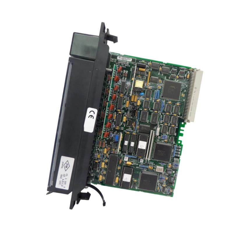
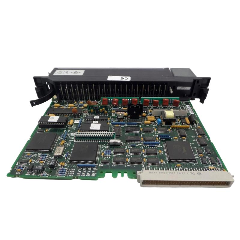
- GE
- IC697ALG230F
- Analog Input Basic Converter Module
- USA
- 138 × 70 × 25 mm
- 0.8 kg
- Xiamen, China
- New & In Stock
- T/T, PayPal, Western Union
- 1 Year
- 1-3 Working Days
- DHL, UPS, TNT, FedEx and EMS.
- 24-Hour Service
- COO
- 44
Our advantage

Global Logistics
We have a 10-year logistics and express cooperation agreement, so our products can be shipped to any place in the world.

Brand new and original
Our products are imported in bulk from the place of origin. Because of the cooperative relationship, our products are all original and 100% new.

24-hour service
We provide 7*24 hours service to our customers. We will be there whenever you need us.

Price advantage
All our products are priced very favorably because we have our own warehouse and supply.
| Company Information | |||
| [email protected] | |||
| Mobile | +8615980777398 | ||
| +8615980777398 | |||
| 15980777398 |
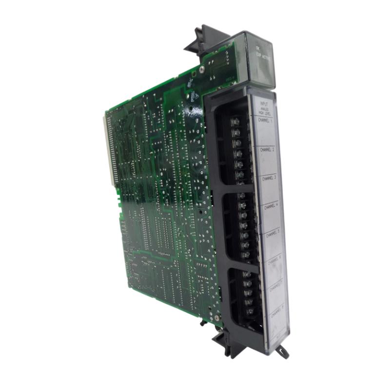
Product Overview
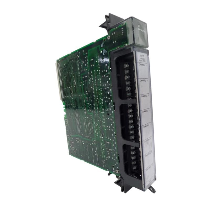
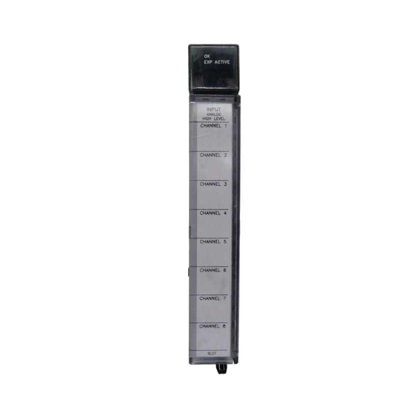
The GE IC697ALG230F Analog Input Basic Converter Module is an industrial PLC interface module designed to receive analog process signals and make those measurements available to a compatible GE control system.
Analog input hardware is essential when an automation system must monitor continuously changing physical conditions rather than simple discrete states. Sensors and transmitters installed throughout a plant can produce electrical signals representing variables such as temperature, pressure, flow, level, position, or other process conditions. The analog input module provides the interface between those field signals and the PLC’s digital control environment.
The supplied specifications for the GE IC697ALG230F are 138 × 70 × 25 mm, with a listed weight of 0.8 kg.
The module should be installed only in the appropriate GE PLC architecture, with the field signal type, wiring, grounding, shielding, and application configuration verified before commissioning.
Product Identification
| Parameter | Specification |
|---|---|
| Manufacturer | GE |
| Model | IC697ALG230F |
| Product Type | Analog Input Basic Converter Module |
| Product Category | Analog Input / Signal Conversion |
| Primary Function | Analog Signal Acquisition and Conversion |
| Application | Industrial Automation |
| Dimensions | 138 × 70 × 25 mm |
| Weight | 0.8 kg |
| Installation | Compatible GE PLC Rack |
| Signal Interface | Analog Field Signals |
| System Role | PLC Analog Input Interface |
| Maintenance | Module, Wiring, Signal, and Configuration Inspection |
Technical Specifications
| Technical Item | Specification |
|---|---|
| Brand | GE |
| Model Number | IC697ALG230F |
| Product Type | Analog Input Basic Converter Module |
| Main Function | Analog Input Signal Conversion |
| Dimensions | 138 × 70 × 25 mm |
| Weight | 0.8 kg |
| Installation Type | PLC Rack Module |
| Application | Industrial Control |
| Signal Processing | Analog Signal Acquisition |
| System Role | Field-to-PLC Analog Interface |
| Maintenance Requirement | Periodic Inspection |
| Primary Service Areas | Module, Field Wiring, Configuration, Signal Quality |
Dimensions and weight are based on the product information supplied for this model. Exact electrical input ranges, channel characteristics, and other application-specific parameters should be confirmed against the applicable system documentation before wiring.
What Is the GE IC697ALG230F?
The GE IC697ALG230F is an analog input interface module intended to connect compatible analog field instrumentation to a GE PLC control system.
The general signal path is:
Process Variable
↓
Sensor / Transmitter
↓
Analog Field Signal
↓
IC697ALG230F
↓
Signal Conversion
↓
PLC Data
↓
Control Program
The PLC can then use the acquired measurement for monitoring, alarms, calculations, sequencing, or closed-loop control.
For example, a pressure transmitter installed on a process line can produce a continuously varying electrical signal. The analog input system receives that signal and provides corresponding data to the PLC application.
Main Functions
Analog Signal Acquisition
The module receives analog information from field instruments.
Signal Conversion
The incoming analog signal is converted into a form that the PLC control architecture can process.
Process Monitoring
Measurements can be incorporated into operator displays, trends, alarms, and process-monitoring functions.
Control Feedback
Analog measurements can provide feedback for control loops where supported by the overall system configuration.
Industrial Instrument Interface
The module forms an interface between field instrumentation and PLC processing.
Role in Industrial Control Systems
An analog input module is one of the most important links between field instrumentation and controller logic.
A typical process-control loop can be represented as:
Sensor
→ Transmitter
→ IC697ALG230F
→ PLC CPU
→ Control Logic
→ Output Device
→ Process
For example:
Pressure Sensor
→ Analog Signal
→ IC697ALG230F
→ PLC
→ Pressure Control Logic
→ Valve / Pump
This arrangement allows the controller to respond to changing process conditions.
Typical Industrial Applications
Manufacturing
The module can support analog measurements used in:
- Machine monitoring
- Temperature control
- Pressure monitoring
- Position measurement
- Production equipment
Process Automation
Potential applications include:
- Flow monitoring
- Tank-level measurement
- Temperature monitoring
- Pressure measurement
- Process feedback
Pump and Motor Systems
Analog feedback can be used for:
- Discharge pressure
- Suction pressure
- Flow
- Speed-related feedback
- Equipment condition monitoring
Water and Wastewater
Applications may include:
- Tank level
- Flow measurement
- Pump pressure
- Process monitoring
- Equipment feedback
Utility and Infrastructure Systems
Analog inputs can be integrated into:
- Plant monitoring
- Auxiliary control
- Environmental monitoring
- Equipment protection
- Industrial utility systems
Analog Signal Architecture
A complete analog measurement chain typically consists of several elements:
1. Field Variable
The physical condition being measured.
2. Sensor
Detects the physical variable.
3. Transmitter
Converts the sensor measurement into a suitable electrical signal.
4. Field Wiring
Carries the signal to the control cabinet.
5. IC697ALG230F
Receives and converts the analog signal for PLC processing.
6. PLC CPU
Processes the converted measurement.
7. Application Logic
Uses the measurement for control, alarms, calculations, or monitoring.
A problem anywhere in this chain can result in an incorrect PLC value.
Installation Guide
1. Verify the Application
Before installing the IC697ALG230F, determine:
- PLC platform
- Rack type
- Module position
- Field device type
- Analog signal type
- Required scaling
- Wiring arrangement
- Grounding strategy
Do not connect an unknown field signal to an analog input module.
2. Verify the Module
Confirm the module identification:
GE IC697ALG230F
Inspect for:
- Cracked housing
- Bent connector
- Damaged contacts
- Contamination
- Signs of overheating
- Mechanical damage
The supplied dimensions are:
138 × 70 × 25 mm
The supplied weight is:
0.8 kg
3. Back Up the PLC Application
Before making hardware changes:
- Back up the PLC program.
- Save the current hardware configuration.
- Record existing module positions.
- Document current analog values.
- Save relevant system parameters.
This provides a useful recovery point during commissioning.
4. Shut Down the Control System
Before installing the module:
- Stop the controlled process.
- Shut down the PLC according to site procedures.
- Isolate applicable electrical power.
- Apply lockout/tagout procedures where required.
- Verify that the equipment is safe to access.
5. Inspect the Rack Position
Inspect the intended installation position.
Look for:
- Bent backplane contacts
- Dust
- Foreign material
- Corrosion
- Mechanical damage
A damaged rack interface can produce intermittent communication or input faults.
6. Install the Module
Align the IC697ALG230F with the designated rack position.
Insert the module evenly until it is fully seated.
Never force the module into position.
If excessive resistance occurs, stop and inspect the rack interface.
7. Secure the Module
Check:
- Full module seating
- Retaining mechanism
- Adjacent module clearance
- Mechanical stability
- Connector engagement
8. Prepare Analog Field Wiring
Before connecting field instruments:
- Identify each input.
- Confirm the transmitter output.
- Verify signal polarity.
- Check signal reference requirements.
- Label each conductor.
- Separate analog cables from high-current wiring where possible.
Good wiring practices are especially important for low-level analog signals.
9. Inspect Shielding and Grounding
Analog measurements can be affected by electrical interference.
Inspect:
- Cable shielding
- Signal reference
- Cabinet grounding
- Instrument grounding
- Shield termination
- Cable routing
Avoid creating unintended ground loops.
10. Configure the Module
Configure the hardware and application according to the actual system requirements.
Typical parameters can include:
- Channel assignment
- Input type
- Signal range
- Scaling
- Engineering units
- Filtering
- Alarm limits
- Data handling
The exact configuration should match the connected instrumentation.
11. Restore Power
After installation and wiring verification:
- Confirm all connections are secure.
- Confirm there are no loose tools or conductors.
- Restore system power.
- Start the PLC.
- Observe module diagnostics.
12. Verify Analog Measurements
Apply a known input condition.
Compare:
Known Field Signal
with
PLC Raw Value
and
PLC Engineering Value
The measurement should correspond to the expected process condition and remain stable.
Commissioning Checklist
| Item | Verification |
|---|---|
| IC697ALG230F Identified | Confirmed |
| Host PLC Verified | Confirmed |
| Rack Position Checked | Confirmed |
| Application Backup Completed | Confirmed |
| Power Isolated | Confirmed |
| Module Inspected | Confirmed |
| Backplane Inspected | Confirmed |
| Field Signal Identified | Confirmed |
| Wiring Verified | Confirmed |
| Shielding Checked | Confirmed |
| Grounding Checked | Confirmed |
| Input Configuration Verified | Confirmed |
| PLC Restarted | Confirmed |
| Analog Value Tested | Confirmed |
| Diagnostics Checked | Confirmed |
Troubleshooting Guide
Analog Input Reads Zero
If an input remains at zero, inspect:
- Field transmitter power
- Sensor output
- Signal wiring
- Polarity
- Signal reference
- Module configuration
- Channel assignment
If possible, measure the field signal independently before replacing the module.
Analog Input Is Unstable
An unstable reading can result from:
- Electrical noise
- Poor shielding
- Grounding problems
- Loose terminals
- Damaged cable
- Sensor instability
- Incorrect configuration
Compare the input signal at the field device with the value received by the PLC.
Analog Value Is Too High
Potential causes include:
- Incorrect scaling
- Incorrect input configuration
- Sensor calibration problem
- Wiring error
- Signal interference
- Incorrect engineering-unit conversion
Verify the signal path from the sensor through the PLC program.
Analog Value Is Too Low
Check:
- Sensor output
- Transmitter power
- Wiring
- Terminals
- Signal reference
- Scaling
- Input configuration
Do not immediately assume the IC697ALG230F is defective.
Analog Value Is Fixed
A value that remains constant despite changing process conditions may indicate:
- Failed transmitter
- Open or shorted wiring
- Configuration problem
- Input channel problem
- Frozen application value
- Module fault
Change the process condition carefully and determine whether the raw input value responds.
Module Is Not Recognized
Possible causes include:
- Poor module seating
- Backplane problem
- Incorrect rack position
- Configuration mismatch
- Power problem
- Hardware failure
Start with physical inspection and controller diagnostics.
Multiple Channels Show Incorrect Values
When several analog inputs exhibit similar problems, investigate common causes first:
- Module power
- Rack connection
- Signal reference
- Grounding
- Shielding
- Configuration
- Environmental electrical noise
A common fault is more likely when multiple channels change simultaneously.
Analog Signal Contains Excessive Noise
Inspect:
- Analog cable routing.
- Shielding.
- Grounding.
- Nearby variable-frequency drives.
- Motor cables.
- Contactors.
- Sensor power.
- Terminal tightness.
Keep analog signal wiring away from high-energy switching circuits wherever practical.
PLC Reports an Input Fault
Record the fault before resetting the system.
Then inspect:
- Module status
- Channel status
- Hardware configuration
- Field wiring
- Sensor condition
- Power supply
- Rack connection
Intermittent faults may disappear temporarily after a restart, so recording the original condition is valuable.
Module Operates Intermittently
Possible causes include:
- Loose module seating
- Poor connector contact
- Vibration
- Temperature fluctuations
- Power instability
- Wiring problems
- Internal hardware degradation
Monitor the system during normal operating conditions rather than testing only during shutdown.
Analog Reading Changes When Motors Start
This condition often suggests electrical interference.
Investigate:
- Cable routing
- Shielding
- Grounding
- Motor power cables
- Variable-frequency drives
- Contactor switching
- Sensor power supply
Compare the analog value before, during, and after motor startup.
Preventive Maintenance
Monthly Inspection
Check:
- Analog values
- Module status
- Sensor readings
- Visible wiring problems
- Cabinet temperature
Quarterly Inspection
Inspect:
- Module seating
- Terminal connections
- Shielding
- Grounding
- Cable routing
- Rack condition
Annual Maintenance
Perform:
- Detailed module inspection
- Signal verification
- Wiring inspection
- Configuration backup
- Calibration review
- Cabinet thermal inspection
In dusty, humid, vibrating, or electrically noisy environments, more frequent inspections may be appropriate.
Analog Signal Troubleshooting Method
When diagnosing an analog input problem, use a structured approach.
Step 1: Check the Process
Determine whether the physical process variable is actually changing.
Step 2: Check the Sensor
Verify that the sensor or transmitter produces the expected signal.
Step 3: Check the Wiring
Inspect continuity, polarity, shielding, grounding, and terminals.
Step 4: Check the Module
Review the IC697ALG230F status and input behavior.
Step 5: Check Configuration
Verify input type, scaling, channel assignment, and engineering units.
Step 6: Check PLC Logic
Confirm that the application is correctly interpreting the analog value.
This approach reduces unnecessary replacement of working hardware.
Replacement Considerations
Before replacing the GE IC697ALG230F, verify:
| Check Item | Purpose |
|---|---|
| Model Number | Confirms correct replacement |
| PLC Platform | Ensures compatibility |
| Rack Position | Confirms physical location |
| Signal Type | Prevents wiring mismatch |
| Field Device | Confirms correct transmitter |
| Wiring | Ensures signal integrity |
| Configuration | Maintains correct operation |
| Scaling | Maintains measurement accuracy |
| Environmental Conditions | Supports reliable service |
Compatible System Components
The IC697ALG230F operates within a complete industrial control architecture.
| Component | Function |
|---|---|
| Analog Sensor | Measures Process Variable |
| Transmitter | Produces Analog Signal |
| Field Wiring | Transfers Signal |
| IC697ALG230F | Analog Input Conversion |
| PLC CPU | Control Processing |
| Digital I/O | Discrete Signal Interface |
| Communication Module | Network Communication |
| Output Module | Control Output |
| Rack / Backplane | Module Interconnection |
| Cabinet Cooling | Thermal Management |
The exact system combination should be verified against the intended GE control-system configuration.
Key Advantages
Direct Analog Integration
The IC697ALG230F provides an interface between field instrumentation and PLC processing.
Process Monitoring
Analog measurements can be used to monitor changing industrial conditions.
Control Feedback
Measurements can be incorporated into control strategies when properly configured within the PLC application.
Compact Form Factor
The supplied dimensions are 138 × 70 × 25 mm, allowing installation within a compact rack arrangement.
Industrial Application
The module is intended for PLC-based industrial automation and process-control environments.
Frequently Asked Questions
What is the GE IC697ALG230F?
The GE IC697ALG230F is an Analog Input Basic Converter Module designed to interface analog field signals with compatible GE PLC systems.
What are the dimensions?
The supplied dimensions are:
138 × 70 × 25 mm
What is the weight?
The listed weight is:
0.8 kg
What does the IC697ALG230F do?
It receives analog signals from compatible field instrumentation and converts the measurements into data that the PLC control system can process.
What process variables can be monitored?
Depending on the connected instrumentation and configured signal type, analog input applications can include:
- Temperature
- Pressure
- Flow
- Level
- Position
- Speed
- Other continuously varying measurements
Why is the analog value unstable?
Common causes include electrical noise, poor grounding, inadequate shielding, loose connections, sensor instability, or incorrect configuration.
Why is the PLC showing an incorrect engineering value?
Possible causes include incorrect scaling, incorrect signal configuration, wiring problems, or sensor/transmitter calibration issues.
How do I determine whether the module is defective?
Measure the field signal independently and compare it with the PLC input. If the field signal is correct but the PLC receives an incorrect value, investigate the wiring, module, and configuration.
Can the IC697ALG230F be replaced while powered?
Unless the specific host system explicitly supports live replacement, power should be isolated before removing or installing the module.
Installation Checklist
| Item | Status |
|---|---|
| Correct IC697ALG230F Identified | ✓ |
| Host PLC Verified | ✓ |
| Rack Position Confirmed | ✓ |
| Application Backed Up | ✓ |
| Power Isolated | ✓ |
| Module Inspected | ✓ |
| Backplane Inspected | ✓ |
| Field Signal Confirmed | ✓ |
| Wiring Verified | ✓ |
| Shielding Checked | ✓ |
| Grounding Checked | ✓ |
| Input Configuration Verified | ✓ |
| PLC Restarted | ✓ |
| Analog Signal Tested | ✓ |
| Engineering Value Verified | ✓ |
Conclusion
The GE IC697ALG230F Analog Input Basic Converter Module provides an interface between industrial analog instrumentation and compatible GE PLC control systems. Its role is to acquire continuously varying field information and make that information available for PLC-based monitoring, control, alarm processing, and other automation functions.
The supplied physical specifications are 138 × 70 × 25 mm, with a listed weight of 0.8 kg. Successful installation requires careful attention to rack compatibility, module seating, field wiring, signal type, shielding, grounding, configuration, and scaling.
When troubleshooting an analog input problem, technicians should examine the entire signal chain rather than immediately replacing the module. Sensor condition, transmitter output, field wiring, electrical interference, module status, configuration, and PLC application logic can all influence the final value displayed by the control system.
With appropriate installation practices and preventive maintenance, the GE IC697ALG230F can provide dependable analog signal interfacing for compatible industrial automation and process-control applications.