

ProductPRODUCT
Featured products

Contact Us
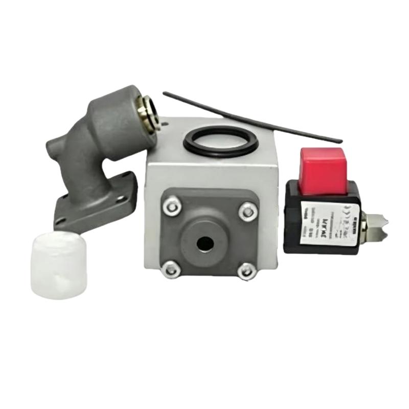
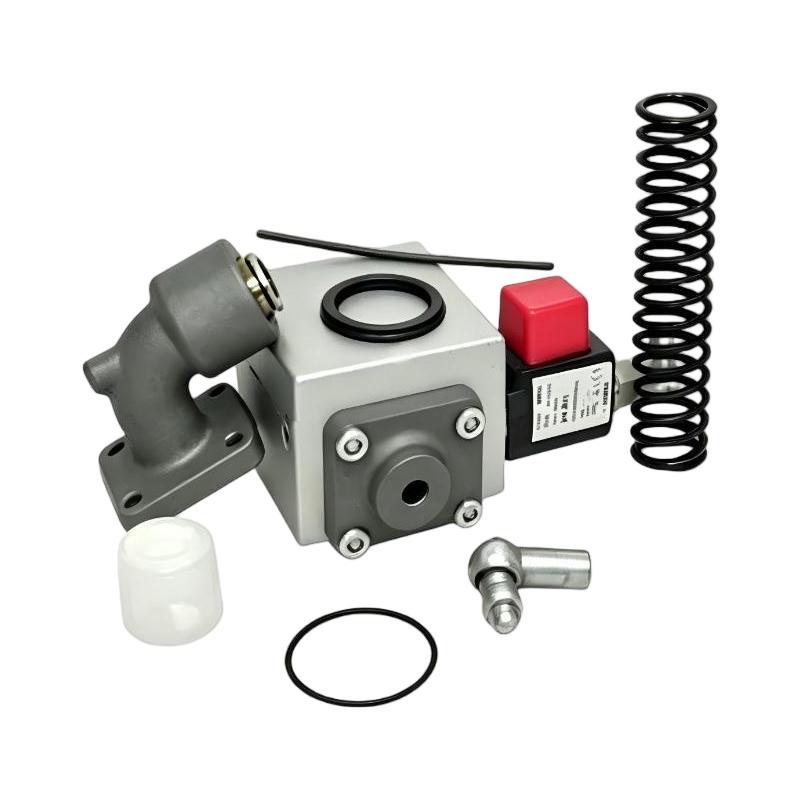
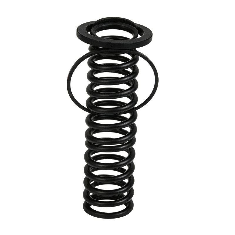
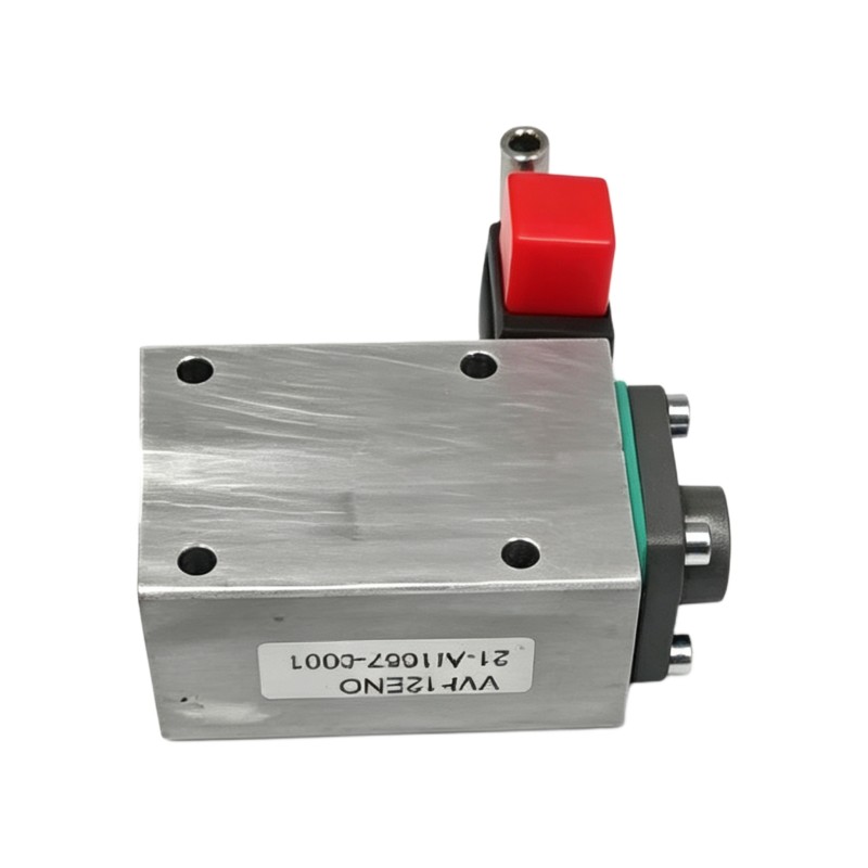
- Ingersoll Rand
- 47704431001 47704440001
- Intake Valve Maintenance Kit
- USA
- 100 x 15 x 80 mm
- 0.4 kg
- Xiamen, China
- New & In Stock
- T/T, PayPal, Western Union
- 1 Year
- 1-3 Working Days
- DHL, UPS, TNT, FedEx and EMS.
- 24-Hour Service
- COO
- 55
Our advantage

Global Logistics
We have a 10-year logistics and express cooperation agreement, so our products can be shipped to any place in the world.

Brand new and original
Our products are imported in bulk from the place of origin. Because of the cooperative relationship, our products are all original and 100% new.

24-hour service
We provide 7*24 hours service to our customers. We will be there whenever you need us.

Price advantage
All our products are priced very favorably because we have our own warehouse and supply.
| Company Information | |||
| [email protected] | |||
| Mobile | +8615980777398 | ||
| +8615980777398 | |||
| 15980777398 |
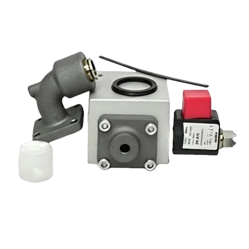
Product Overview
The Ingersoll Rand 47704431001 47704440001 Intake Valve Maintenance Kit is a compressor service component intended for maintenance of compatible oil-injected compressed-air systems. The intake valve controls the flow of atmospheric air entering the compressor during different operating conditions, including startup, loading, unloading, and capacity regulation.
In a rotary screw compressor, the intake valve is closely associated with compressor capacity control. When the compressor requires compressed air, the intake valve allows an appropriate amount of air into the compression element. During unloading or reduced-demand conditions, the valve restricts or closes the intake path to reduce unnecessary compression work.
A properly maintained intake valve helps support:
- Stable compressor loading
- Correct air intake
- Efficient capacity control
- Reliable startup
- Proper unloading
- Reduced energy consumption
- Stable compressor operation
The supplied product information identifies the component as an Ingersoll Rand 47704431001 47704440001 Intake Valve Maintenance Kit, with dimensions of 100 × 15 × 80 mm and a weight of 0.4 kg.
Product Information
- Manufacturer: Ingersoll Rand
- Service Kit Number: 47704431001
- Component Number: 47704440001
- Product Type: Intake Valve Maintenance Kit
- Dimensions: 100 × 15 × 80 mm
- Weight: 0.4 kg
- Application: Oil-Injected Air Compressor Systems
- Primary Function: Compressor Air Intake and Capacity Control
Technical Specifications
| Parameter | Specification |
|---|---|
| Manufacturer | Ingersoll Rand |
| Service Kit Number | 47704431001 |
| Component Number | 47704440001 |
| Product Type | Intake Valve Maintenance Kit |
| Dimensions | 100 × 15 × 80 mm |
| Weight | 0.4 kg |
| Application | Industrial Air Compressor |
| Function | Intake Air Regulation |
| Installation | Compressor Air Intake Circuit |
| Maintenance | Valve Inspection and Service |
The dimensions and weight above are based on the supplied product information. Compatibility should be verified against the specific compressor configuration before installation.
Function and Working Principle
The intake valve regulates the amount of air entering the compressor’s compression element.
A simplified operating sequence is:
Atmospheric Air
↓
Air Intake Filter
↓
Intake Valve
↓
Compression Element
↓
Air-Oil Separation
↓
Minimum Pressure Control
↓
Compressed-Air Outlet
During loaded operation, the intake valve opens sufficiently to allow the compressor to receive the required air volume.
During unloading, the valve restricts or closes the intake path while the compressor transitions to a lower-load condition.
The exact control mechanism depends on the compressor design, but the valve typically works together with:
- Pressure-control components
- Solenoid valves
- Pneumatic control lines
- Controller
- Compressor inlet filter
- Blowdown or unloading circuit
Why the Intake Valve Is Important
The intake valve directly affects the amount of air entering the compressor.
If the valve does not open sufficiently:
- Compressor capacity can decrease.
- Discharge pressure may build slowly.
- Air production may be insufficient.
- Compressor loading can become unstable.
If the valve does not close correctly:
- The compressor may continue compressing air during unloading.
- Energy consumption can increase.
- Unloading performance can deteriorate.
- Internal pressure may not decrease correctly.
The intake valve therefore plays an important role in both compressor performance and energy efficiency.
Industrial Applications
Rotary Screw Compressors
The maintenance kit is primarily intended for service of compatible oil-injected rotary screw compressor intake systems.
Manufacturing Plants
Supports compressed-air generation for pneumatic equipment, automation, tools, and production lines.
Automotive Manufacturing
Helps maintain stable compressed-air production for assembly and automated equipment.
Food and Beverage
Supports reliable compressor operation for production and utility systems.
Pharmaceutical Manufacturing
Helps maintain stable compressed-air equipment during continuous production.
General Industrial Facilities
Useful for scheduled maintenance of plant compressed-air systems.
Installation Guide
Step 1 – Verify the Maintenance Kit
Confirm:
Ingersoll Rand 47704431001
Component 47704440001
Intake Valve Maintenance Kit
Confirm compatibility with the compressor before beginning disassembly.
Step 2 – Shut Down the Compressor
Before maintenance:
- Stop the compressor normally.
- Isolate electrical power.
- Prevent automatic restart.
- Isolate the compressor from the plant air system where required.
- Relieve internal pressure.
- Allow the compressor to cool.
Never disassemble an intake valve assembly while the compressor remains pressurized.
Step 3 – Prepare the Work Area
Prepare:
- Replacement maintenance kit
- Suitable hand tools
- Replacement seals
- Clean lint-free cloths
- Appropriate protective equipment
- Suitable cleaning materials
Keep the intake system clean to prevent contamination from entering the compressor element.
Step 4 – Locate the Intake Valve
Identify the intake valve between the compressor’s air intake filter and compression element.
Inspect:
- Valve body
- Air inlet
- Control connections
- Pneumatic lines
- Seals
- Moving components
- Mounting hardware
Record the original connection arrangement before disassembly.
Step 5 – Disconnect Control Lines
If the valve uses pneumatic or control connections:
- Identify each line.
- Label connections if necessary.
- Disconnect lines carefully.
- Inspect tubing for cracks or contamination.
Damaged control tubing can cause symptoms that appear to be intake-valve faults.
Step 6 – Remove the Existing Valve Components
Carefully remove the valve assembly and associated service components.
Depending on the specific compressor configuration, the intake valve may include:
- Valve element
- Piston
- Spring
- Seals
- Retaining components
- Control components
Keep removed components organized for inspection.
Step 7 – Inspect the Valve Housing
Check for:
- Mechanical wear
- Scratches
- Corrosion
- Dirt
- Oil deposits
- Damaged sealing surfaces
- Foreign material
A repair or maintenance kit can restore worn service components, but a severely damaged valve body may require additional replacement.
Step 8 – Clean the Valve
Clean the valve housing and internal passages carefully.
Remove:
- Dust
- Oil deposits
- Carbon-like contamination
- Foreign particles
- Old seal material
Avoid abrasive cleaning methods that could damage precision surfaces.
Step 9 – Install the Maintenance Kit
Install the new service components from the 47704440001 Intake Valve Maintenance Kit.
Pay particular attention to:
- Seal orientation
- Spring position
- Valve element orientation
- Piston position
- Retaining components
Use suitable assembly practices for compressor seals and moving components.
Step 10 – Check Valve Movement
After assembly, verify that moving components can operate smoothly.
The valve should not:
- Stick
- Bind
- Move excessively
- Remain partially open unintentionally
If abnormal mechanical resistance exists, inspect the assembly again before installation.
Step 11 – Reinstall the Intake Valve
Install the serviced valve in its original position.
Verify:
- Correct airflow direction
- Proper mounting
- Secure fasteners
- Correct seals
- Correct pneumatic connections
- Correct control-line routing
Step 12 – Inspect the Intake System
Before startup, inspect:
- Intake filter
- Intake piping
- Valve connections
- Control tubing
- Valve housing
- Mounting hardware
Make sure no foreign material has entered the compressor intake.
Commissioning Procedure
After maintenance:
- Restore the compressor to normal configuration.
- Restore electrical power.
- Start the compressor.
- Observe startup behavior.
- Monitor suction or intake conditions where available.
- Verify compressor loading.
- Verify unloading.
- Monitor discharge pressure.
- Check for abnormal noise.
- Confirm stable compressor operation.
Troubleshooting Guide
Problem 1 – Compressor Will Not Load
Possible causes:
- Intake valve stuck closed
- Control signal problem
- Pneumatic line blockage
- Solenoid malfunction
- Damaged valve components
- Incorrect maintenance-kit installation
Diagnostic Procedure
- Check compressor control status.
- Verify control signals.
- Inspect pneumatic lines.
- Check valve movement.
- Inspect seals and moving components.
- Verify correct assembly.
Problem 2 – Compressor Loads Slowly
Possible causes:
- Intake valve partially restricted
- Intake filter blocked
- Valve sticking
- Control pressure problem
- Damaged seals
- Excessive air demand
Inspect the complete intake and capacity-control system.
Problem 3 – Compressor Cannot Reach Rated Capacity
Possible causes:
- Intake valve not fully open
- Blocked intake filter
- Control-system problem
- Air leakage
- Compressor element problem
- Incorrect operating conditions
Verify that the intake valve reaches the correct operating position.
Problem 4 – Compressor Does Not Unload
Possible causes:
- Intake valve stuck open
- Control solenoid problem
- Blocked pneumatic line
- Damaged valve components
- Controller fault
A valve that cannot close or restrict intake flow can prevent proper unloading.
Problem 5 – Excessive Energy Consumption During Unloading
Possible causes:
- Intake valve leakage
- Valve not closing fully
- Incorrect control signal
- Pneumatic control problem
- Damaged seals
Check whether the valve reaches its intended unloaded position.
Problem 6 – Compressor Pressure Is Unstable
Possible causes:
- Intake valve sticking
- Control pressure fluctuation
- Solenoid instability
- Pressure-sensing problem
- Variable air demand
Monitor valve movement together with control-system behavior.
Problem 7 – Abnormal Noise at Intake
Possible causes:
- Valve vibration
- Loose component
- Damaged valve element
- Intake restriction
- Foreign material
Inspect the intake system immediately if unusual mechanical noise occurs.
Problem 8 – Excessive Compressor Cycling
Possible causes:
- Intake valve control problem
- Incorrect pressure settings
- Pressure sensor issue
- Rapid changes in plant air demand
- Controller problem
Do not assume the intake valve is the only possible cause.
Problem 9 – Intake Valve Leakage
Possible causes:
- Damaged seal
- Worn valve seat
- Contamination
- Incorrect assembly
- Damaged valve element
Inspect the valve after safely isolating the compressor.
Problem 10 – Maintenance Kit Does Not Resolve the Fault
If the compressor still has loading or unloading problems after maintenance, inspect:
- Control solenoid
- Pneumatic lines
- Pressure sensors
- Controller
- Intake filter
- Air piping
- Compressor element
- Electrical control circuit
The intake valve should always be diagnosed as part of the complete compressor control system.
Fault Diagnosis Flow
A systematic troubleshooting sequence is:
Compressor Control Command
↓
Control Signal
↓
Pneumatic Circuit
↓
Intake Valve
↓
Valve Movement
↓
Intake Airflow
↓
Compressor Loading
↓
Discharge Pressure
↓
Unloading Operation
This sequence helps identify whether the problem is mechanical, pneumatic, electrical, or control-related.
Intake Valve Maintenance Procedure
Preparation
- Confirm the maintenance kit number.
- Verify compressor compatibility.
- Shut down the compressor.
- Isolate electrical power.
- Relieve pressure.
- Allow the equipment to cool.
Removal
- Open the appropriate service access.
- Locate the intake valve.
- Label control lines.
- Disconnect control connections.
- Remove the valve assembly.
- Place components on a clean work surface.
Inspection
Inspect:
- Valve housing
- Valve element
- Piston
- Spring
- Seals
- Control connections
- Air passages
Look for wear, contamination, corrosion, and mechanical damage.
Cleaning
Clean reusable components carefully.
Remove dirt, oil deposits, and foreign material.
Maintenance Kit Installation
- Replace worn service components.
- Install new seals.
- Install spring components correctly.
- Verify valve element orientation.
- Reassemble the valve.
- Check smooth mechanical movement.
Reinstallation
- Install the serviced intake valve.
- Reconnect control lines.
- Secure mounting components.
- Verify airflow direction.
- Inspect all connections.
Startup and Testing
- Restore electrical power.
- Start the compressor.
- Verify startup.
- Test loading.
- Test unloading.
- Monitor pressure.
- Check for abnormal noise.
- Record maintenance results.
Preventive Maintenance
| Maintenance Item | Recommended Action |
|---|---|
| Intake Valve | Inspect during scheduled service |
| Valve Movement | Check for sticking |
| Seals | Inspect for leakage |
| Intake Filter | Keep clean |
| Control Lines | Check for cracks or blockage |
| Solenoid | Verify operation |
| Pneumatic Circuit | Check pressure and leakage |
| Compressor Loading | Verify normal operation |
| Compressor Unloading | Verify valve closes correctly |
| Maintenance Records | Record service work |
Factors Affecting Intake Valve Service Life
The service life of intake valve components can be affected by:
- Compressor operating hours
- Air quality
- Intake contamination
- Oil contamination
- Frequent loading and unloading
- High operating temperature
- Mechanical wear
- Control-system condition
- Maintenance quality
- Incorrect installation
Keeping the compressor intake clean and maintaining the control system can help reduce premature valve wear.
Common Installation Mistakes
Incorrect Kit Identification
Using an incompatible maintenance kit can result in incorrect valve performance.
Incorrect Seal Installation
A poorly installed seal can cause leakage and unstable operation.
Incorrect Spring Position
Incorrect spring installation can change valve response.
Contaminated Valve Components
Dirt can cause valve sticking and accelerated wear.
Incorrect Control-Line Routing
Incorrect pneumatic connections can prevent proper loading or unloading.
Intake Filter Neglect
A restricted intake filter can cause symptoms similar to an intake valve problem.
Incorrect Valve Orientation
Improper orientation can interfere with airflow.
Excessive Tightening
Overtightening can damage fittings or valve components.
Failure to Relieve Pressure
Residual pressure creates a serious maintenance hazard.
Skipping Operational Testing
The compressor should be tested under both loading and unloading conditions after maintenance.
Key Advantages
- Designed for compatible Ingersoll Rand compressor systems
- Supports intake-air regulation
- Helps maintain stable compressor loading
- Supports proper unloading
- Helps maintain compressor capacity
- Supports efficient compressor operation
- Compact dimensions of 100 × 15 × 80 mm
- Lightweight design at 0.4 kg
- Suitable for scheduled valve maintenance
- Helps reduce intake-control-related downtime
Technical FAQs
What is the Ingersoll Rand 47704431001 47704440001?
It is an Intake Valve Maintenance Kit designed for maintenance of compatible Ingersoll Rand compressor intake valve assemblies.
What does the intake valve do?
It regulates the amount of atmospheric air entering the compressor’s compression element and supports compressor loading and unloading.
What are the dimensions?
The supplied dimensions are 100 × 15 × 80 mm.
What is the weight?
The supplied weight is 0.4 kg.
Why will a compressor not load?
Possible causes include a closed or restricted intake valve, control-signal problems, pneumatic faults, a blocked intake filter, or compressor control problems.
Why does the compressor fail to unload?
An intake valve that remains open, a faulty solenoid, blocked control tubing, or damaged valve components can prevent proper unloading.
Can an intake valve affect compressor energy consumption?
Yes. If the valve does not regulate intake air correctly during loading and unloading, compressor energy consumption can increase.
Why does the compressor load slowly?
Possible causes include a partially restricted intake valve, blocked intake filter, control-pressure problems, valve sticking, or excessive downstream air demand.
Why should the pneumatic control circuit be inspected?
The intake valve may be mechanically healthy while a faulty solenoid, blocked tube, or inadequate control pressure prevents it from operating correctly.
How should the intake valve be maintained?
Inspect valve movement, seals, springs, control lines, intake filter condition, and loading/unloading performance during scheduled compressor maintenance.
When should the maintenance kit be used?
The kit can be used when service components within the compatible intake valve assembly are worn, contaminated, or damaged and the valve housing remains suitable for continued service.
Conclusion
The Ingersoll Rand 47704431001 47704440001 Intake Valve Maintenance Kit is an important compressor maintenance component for compatible oil-injected compressed-air systems. The intake valve regulates the air entering the compressor and plays a key role in capacity control, loading, unloading, and efficient operation.
The supplied maintenance kit dimensions are 100 × 15 × 80 mm, with a weight of 0.4 kg. Proper servicing requires safe pressure isolation, careful valve disassembly, inspection of mechanical components, correct seal installation, accurate control-line reconnection, and functional testing after reassembly.
When troubleshooting, technicians should evaluate the intake valve together with the intake filter, pneumatic control circuit, solenoids, pressure sensors, controller, and compressor operating conditions. A systematic approach can prevent unnecessary component replacement and help identify the actual source of loading, unloading, capacity, or pressure-related problems.
Regular intake valve maintenance can help maintain stable compressor performance, improve capacity control, reduce unnecessary energy consumption, and minimize unexpected downtime.