

ProductPRODUCT
Featured products
Contact Us
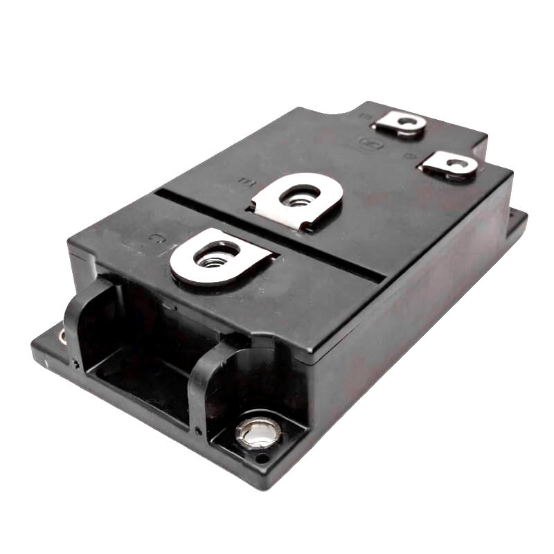
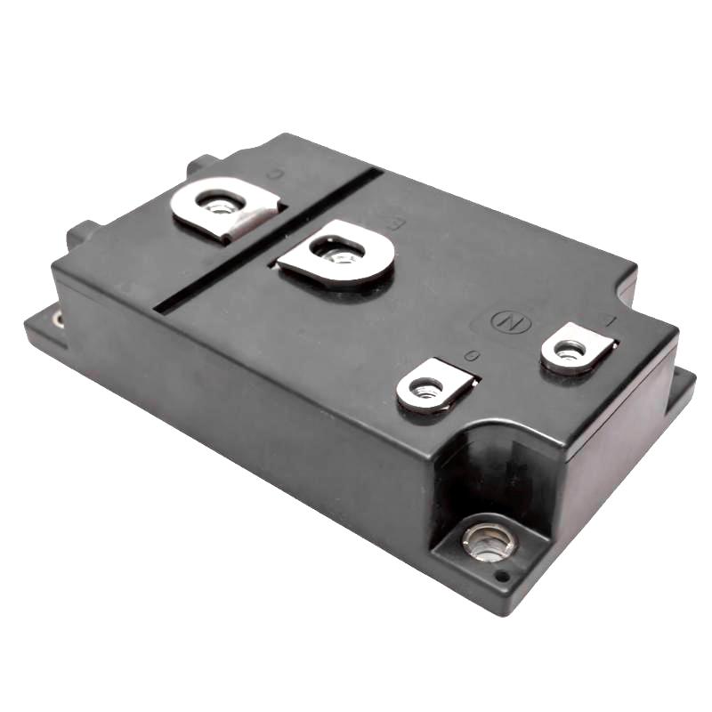
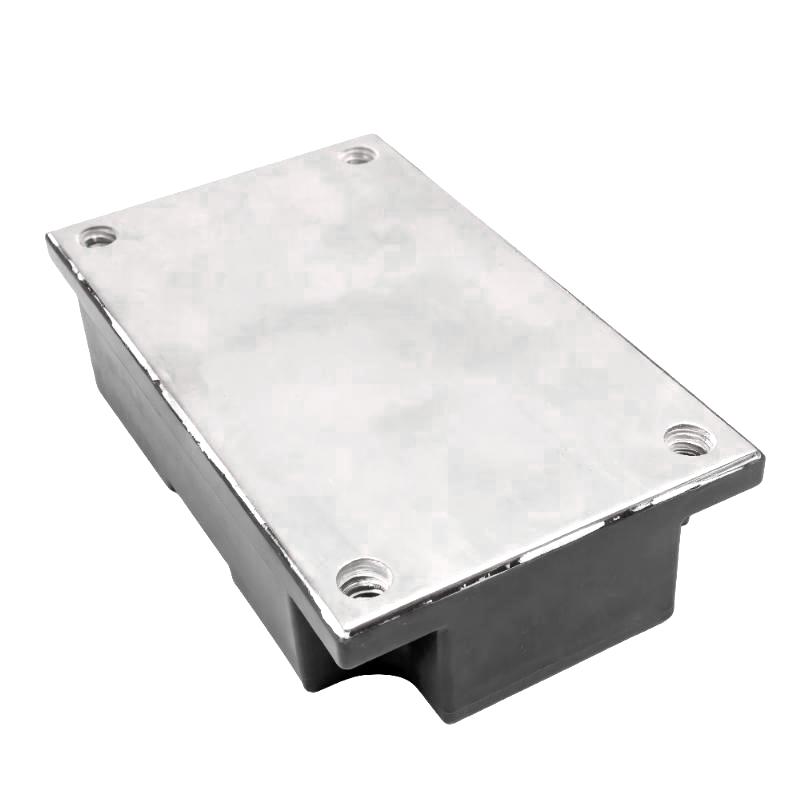
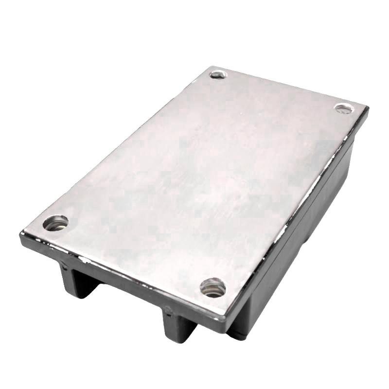
- Allen Bradley
- 1336-QOUT-SP12B
- Transistor Output Assembly Kit
- USA
- 150 × 35 × 100 mm
- 0.89 kg
- Xiamen, China
- New & In Stock
- T/T, PayPal, Western Union
- 1 Year
- 1-3 Working Days
- DHL, UPS, TNT, FedEx and EMS.
- 24-Hour Service
- COO
- 54
Our advantage

Global Logistics
We have a 10-year logistics and express cooperation agreement, so our products can be shipped to any place in the world.

Brand new and original
Our products are imported in bulk from the place of origin. Because of the cooperative relationship, our products are all original and 100% new.

24-hour service
We provide 7*24 hours service to our customers. We will be there whenever you need us.

Price advantage
All our products are priced very favorably because we have our own warehouse and supply.
| Company Information | |||
| [email protected] | |||
| Mobile | +8615980777398 | ||
| +8615980777398 | |||
| 15980777398 |
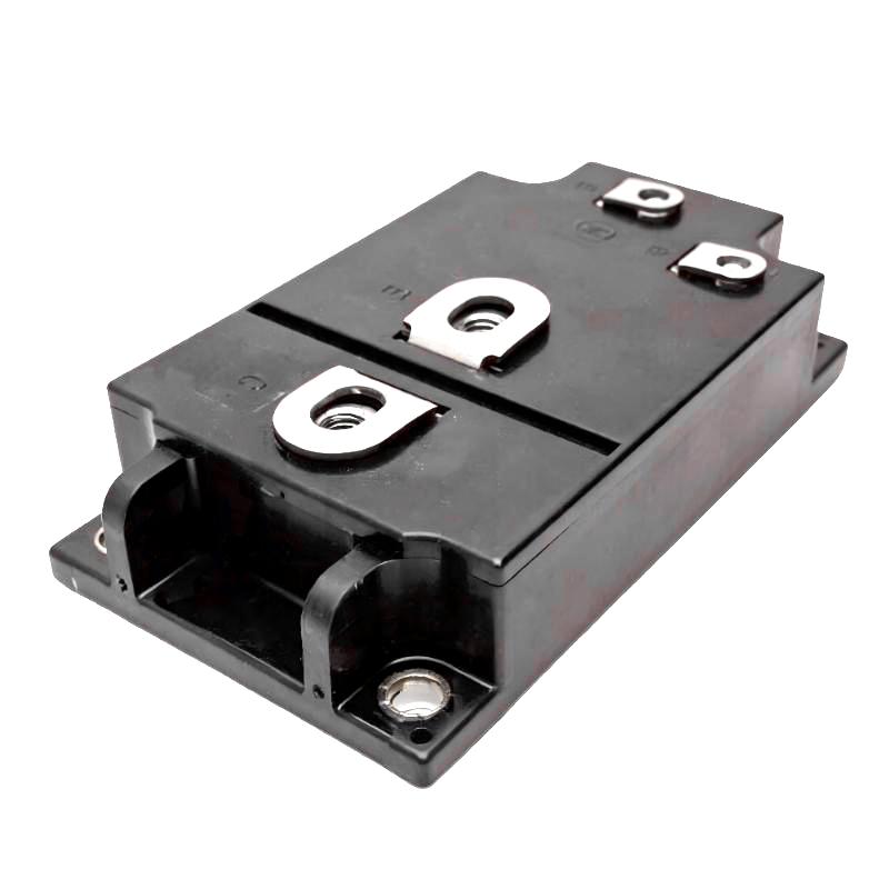
Product Overview
The Allen Bradley 1336-QOUT-SP12B Transistor Output Assembly Kit is a power electronic assembly associated with Allen Bradley 1336 series industrial drive systems. It is designed around the transistor output section of the drive, where switching devices are used to control electrical power delivered to the motor.
The transistor output stage is one of the most important sections of a variable frequency drive. It takes the DC voltage from the drive’s intermediate DC bus and switches it in a controlled sequence to produce the variable-frequency, variable-voltage output required by the motor.
As an assembly kit, the 1336-QOUT-SP12B is intended for drive maintenance and component replacement rather than general-purpose transistor applications. Its correct use depends on the associated drive model, power configuration, and the design of the original output stage.
Technical Specifications
| Parameter | Details |
|---|---|
| Manufacturer | Allen Bradley |
| Model | 1336-QOUT-SP12B |
| Product Type | Transistor Output Assembly Kit |
| Series | 1336 Series |
| Main Function | Drive Transistor Output Switching |
| System Role | Inverter Power Output Assembly |
| Application | Industrial Motor Drives |
| Typical Use | Variable Frequency Drive Power Stage |
| Dimensions | 150 × 35 × 100 mm |
| Weight | 0.89 kg |
| Application Area | Industrial Automation and Motor Control |
Product Features
The 1336-QOUT-SP12B is associated with the output power section of compatible 1336 series drives.
Key characteristics include:
- Transistor output assembly design
- Associated with Allen Bradley 1336 series drive hardware
- Supports controlled power switching
- Forms part of the drive inverter output stage
- Interfaces with the drive’s DC bus and motor output circuit
- Suitable for industrial motor control applications
- Assembly-kit configuration for maintenance purposes
- Dimensions of 150 × 35 × 100 mm
- Stated weight of 0.89 kg
- Designed for integration into compatible drive power electronics
The output assembly operates under significant electrical and thermal stress during normal drive operation, making correct component selection and installation important.
Working Principle
The transistor output assembly works on the inverter side of the drive’s power conversion system.
A simplified power path is:
AC Input → Rectifier → DC Bus → Transistor Output Stage → Motor
The rectifier first converts the incoming AC supply into DC. The DC bus then provides the energy required by the inverter. The transistor output stage rapidly switches this DC power according to commands from the drive control circuitry.
By controlling the timing and sequence of these switching operations, the drive creates a controlled three-phase output waveform. This allows the motor’s speed and torque to be regulated without directly switching the incoming AC supply on and off at the motor.
The transistor output stage therefore has a direct influence on motor operation and drive performance.
Role in Allen Bradley 1336 Drives
The 1336-QOUT-SP12B belongs to the drive’s power output section.
| Function | Description |
|---|---|
| Power Switching | Controls the switching of DC bus energy |
| Inverter Output | Generates controlled electrical output for the motor |
| Motor Control Support | Enables variable-frequency motor operation |
| Switching Coordination | Works with gate-drive circuitry |
| Power Conversion | Converts DC-link energy into controlled AC output |
| Drive Integration | Forms part of the 1336 power-stage architecture |
The transistor output section works closely with the gate driver, DC bus, control electronics, current feedback, and thermal management system.
Industrial Applications
The 1336-QOUT-SP12B is intended for compatible industrial motor drive applications.
| Application | Typical Use |
|---|---|
| Conveyor Systems | Motor speed and acceleration control |
| Pumps | Variable-speed pump operation |
| Fans | Controlled fan speed |
| Material Handling | Motor-driven equipment |
| Production Machinery | Automated motor control |
| Machine Tools | Motor speed regulation |
| Process Equipment | Controlled motor operation |
| Industrial Automation | Variable-speed drive integration |
The actual application depends on the drive model and power rating in which the output assembly is installed.
Installation and Maintenance
The transistor output assembly is part of the high-power section of the drive. Appropriate electrical safety procedures are essential when inspecting or replacing this component.
Before maintenance, the drive must be isolated from the relevant power sources and the DC bus voltage must be verified to have reached a safe level according to the applicable service procedure.
Recommended inspection steps include:
- Confirm the complete 1336-QOUT-SP12B part number.
- Verify the associated 1336 drive model.
- Check the drive’s power configuration.
- Inspect the transistor assembly for physical damage.
- Look for signs of overheating or discoloration.
- Check power terminals and electrical connections.
- Inspect the associated gate-driver circuit.
- Check the DC bus and bus capacitor condition.
- Inspect cooling components and airflow paths.
- Check for possible motor-side short circuits.
- Verify correct installation before energizing the drive.
- Perform appropriate drive testing after replacement.
If an output transistor assembly fails, replacing the assembly without investigating the original cause may result in another failure. Motor insulation problems, excessive current, cooling issues, DC bus abnormalities, or gate-driver faults can all contribute to output-stage damage.
Related Drive Components
The transistor output assembly is only one part of the drive’s complete power conversion system.
| Component | Function |
|---|---|
| Bridge Rectifier | Converts AC input into rectified DC |
| Bus Capacitor | Stores and filters DC-link energy |
| Precharge Circuit | Controls initial DC bus charging |
| Gate Driver | Provides switching control signals |
| Transistor Output Assembly | Performs high-power switching |
| Control Board | Generates drive control commands |
| Current Sensors | Monitor output and motor current |
| Cooling System | Removes heat from power components |
| Motor | Converts electrical power into mechanical output |
A complete diagnostic process should consider these components together when an inverter or output-stage fault occurs.
Recommended Related Models
| Model / Component | Type | Primary Function | Application |
|---|---|---|---|
| Allen Bradley 1336-QOUT-SP12B | Transistor Output Assembly Kit | Inverter power switching | 1336 series drives |
| Allen Bradley 1336-BDB-SP31C | Gate Driver | Transistor gate control | 1336 series drives |
| Allen Bradley 1336-CAP-SP15A | Bus Capacitor | DC bus energy storage | 1336 series drives |
| Allen Bradley 1336-BR-SP5A | Bridge Rectifier | AC-to-DC rectification | 1336 series drives |
| Allen Bradley 1336-PB-SP5A | Precharge Circuit Board | DC bus precharge control | 1336 series drives |
When selecting a replacement output assembly, the drive model, output rating, transistor configuration, gate-driver interface, mounting arrangement, and complete part number should be checked. A component with a similar physical size may not have the same electrical characteristics.
Key Advantages
- Provides a dedicated transistor output assembly
- Supports inverter power switching
- Associated with Allen Bradley 1336 series drive hardware
- Supports controlled motor output
- Works with the drive gate-driver and DC bus circuits
- Suitable for industrial variable frequency drive applications
- Dimensions of 150 × 35 × 100 mm
- Stated weight of 0.89 kg
- Suitable for drive maintenance and power-stage replacement
Technical FAQs
What is the function of the transistor output assembly in a 1336 drive?
The transistor output assembly performs the high-speed power switching required by the inverter. It converts energy from the DC bus into a controlled electrical output that can regulate the connected motor.
What conditions can cause an inverter transistor assembly to fail?
Excessive motor current, short circuits, inadequate cooling, abnormal DC bus voltage, switching problems, motor insulation faults, and gate-driver failures can all place significant stress on the output transistors.
Why should the gate-driver circuit be inspected after an output transistor failure?
The gate driver controls the switching devices directly. If the driver produces an abnormal gate signal or fails to switch the transistor correctly, a replacement output assembly can be exposed to the same damaging condition.
How can a technician determine whether an output-stage fault is actually caused by the motor?
The motor circuit should be checked for phase-to-phase abnormalities, insulation problems, grounding faults, and other conditions that could produce excessive current. The drive’s current and fault history can also provide useful diagnostic information.
Does the 1336-QOUT-SP12B replace any transistor assembly with the same dimensions?
No. The electrical rating, switching characteristics, gate interface, mechanical arrangement, and compatibility with the specific 1336 drive must all be confirmed. Physical dimensions alone are not enough to establish interchangeability.