

ProductPRODUCT
Featured products
Contact Us
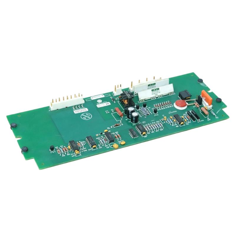
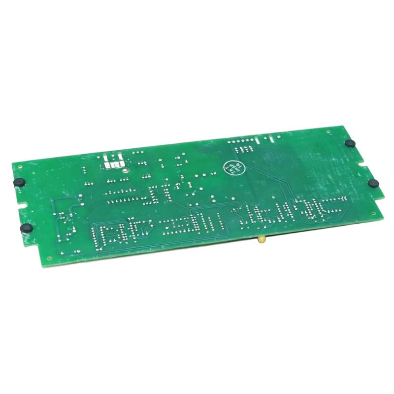
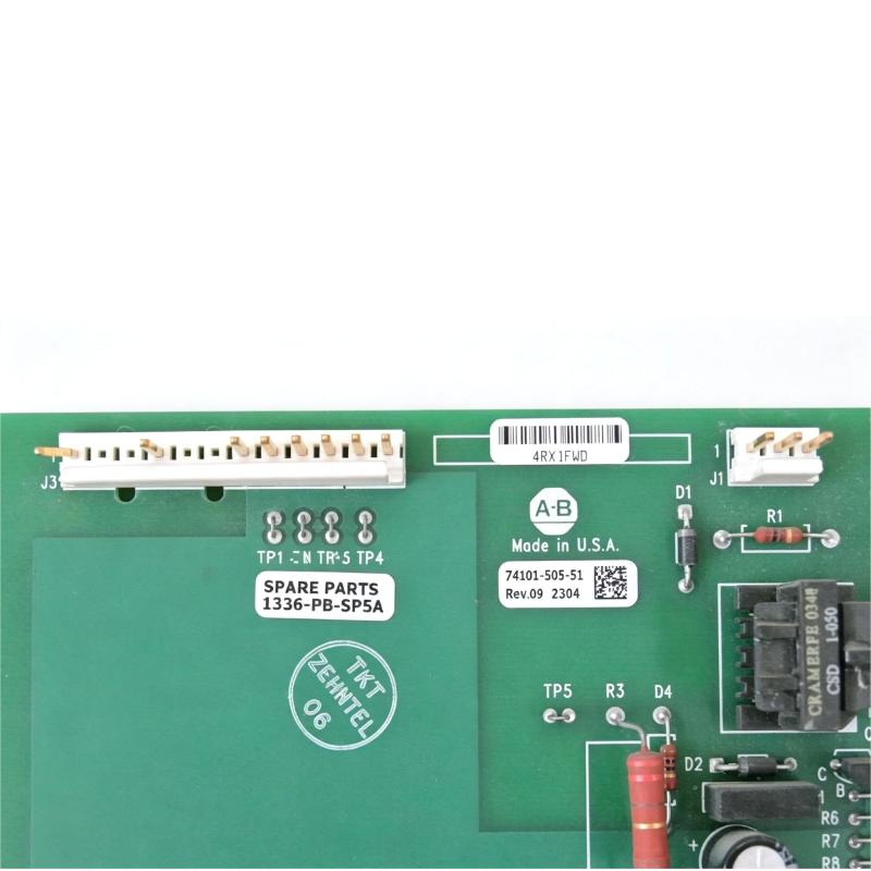
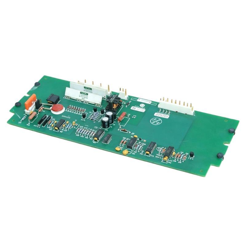
- Allen Bradley
- 1336-PB-SP5A
- Precharge Circuit Board
- USA
- 130 × 25 × 100 mm
- 0.16 kg
- Xiamen, China
- New & In Stock
- T/T, PayPal, Western Union
- 1 Year
- 1-3 Working Days
- DHL, UPS, TNT, FedEx and EMS.
- 24-Hour Service
- COO
- 60
Our advantage

Global Logistics
We have a 10-year logistics and express cooperation agreement, so our products can be shipped to any place in the world.

Brand new and original
Our products are imported in bulk from the place of origin. Because of the cooperative relationship, our products are all original and 100% new.

24-hour service
We provide 7*24 hours service to our customers. We will be there whenever you need us.

Price advantage
All our products are priced very favorably because we have our own warehouse and supply.
| Company Information | |||
| [email protected] | |||
| Mobile | +8615980777398 | ||
| +8615980777398 | |||
| 15980777398 |
Product Overview
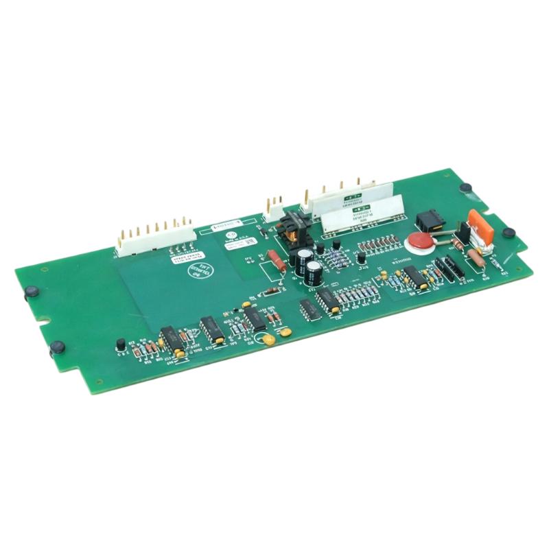
The Allen Bradley 1336-PB-SP5A Precharge Circuit Board is a specialized electronic component used in the power section of compatible Allen Bradley 1336 series drive systems. Its function is associated with the drive’s precharge circuit, which controls the initial charging of the DC bus before the main power circuit enters normal operation.
When a drive is first energized, the DC bus capacitors can initially appear as a very low impedance load. Applying full input power directly to a discharged capacitor bank can produce a large inrush current. A precharge circuit is used to limit and manage this initial current, reducing electrical stress on the capacitors, rectifier, switching components, and associated power circuitry.
The 1336-PB-SP5A therefore works as part of the drive’s startup and DC-link power management system. It is not a standalone motor controller or general-purpose circuit board, and its compatibility should be considered together with the associated drive model and hardware configuration.
Technical Specifications
| Parameter | Details |
|---|---|
| Manufacturer | Allen Bradley |
| Model | 1336-PB-SP5A |
| Product Type | Precharge Circuit Board |
| Series | 1336 Series |
| Main Function | DC Bus Precharge Control |
| System Role | Drive Power Management |
| Application | Industrial Motor Drives |
| Typical Use | DC-Link Precharge and Inrush Current Management |
| Dimensions | 130 × 25 × 100 mm |
| Weight | 0.16 kg |
| Application Area | Industrial Automation and Motor Control |
Product Features
The 1336-PB-SP5A provides control and circuitry associated with the initial energization of the drive’s DC bus.
Key characteristics include:
- Precharge circuit board design
- Associated with Allen Bradley 1336 series drive hardware
- Supports controlled DC bus capacitor charging
- Helps limit initial charging current
- Works with the drive’s DC-link circuit
- Supports proper startup of the power section
- Compact 130 × 25 × 100 mm construction
- Stated weight of 0.16 kg
- Designed for integration into industrial drive electronics
The precharge circuit is particularly important during startup because the DC bus capacitors must be charged in a controlled manner before the drive transitions into normal operating conditions.
Working Principle
The precharge circuit manages the initial charging stage of the DC bus.
A simplified sequence is:
AC Input → Rectifier → Precharge Circuit → DC Bus Capacitors → Inverter Power Stage
When the drive is first energized, the precharge circuit limits the current flowing into the discharged DC bus capacitors. As the bus voltage rises toward its normal operating level, the drive can transition from the precharge condition to normal operation.
Without suitable inrush-current management, the initial charging current could place excessive stress on the rectifier, capacitors, wiring, and other power components.
The precharge circuit therefore serves as a controlled transition between the incoming power supply and the fully energized DC link.
Role in Allen Bradley 1336 Drives
The 1336-PB-SP5A is part of the startup and DC bus management section of the drive.
| Function | Description |
|---|---|
| Precharge Control | Manages initial DC bus charging |
| Inrush Current Limiting | Helps reduce the initial charging current |
| DC-Link Protection | Reduces electrical stress during startup |
| Startup Management | Supports controlled energization of the power section |
| Power Circuit Coordination | Works with the rectifier and DC bus |
| Drive Integration | Forms part of the overall 1336 drive architecture |
A problem in the precharge circuit can prevent the DC bus from reaching the expected operating condition and may result in startup faults or repeated attempts to initialize the drive.
Industrial Applications
The 1336-PB-SP5A is intended for compatible industrial motor drive systems.
| Application | Typical Use |
|---|---|
| Conveyor Systems | Controlled motor startup |
| Pumps | Variable-speed motor control |
| Fans | Industrial fan drive systems |
| Material Handling | Motor acceleration and control |
| Production Machinery | Automated motor operation |
| Machine Tools | Controlled drive startup |
| Process Equipment | Variable-speed operation |
| Industrial Automation | Motor drive integration |
Its specific application depends on the 1336 drive configuration in which the board is installed.
Installation and Maintenance
The precharge circuit is directly associated with the drive’s DC bus and power electronics. The DC bus may remain energized after the incoming AC supply has been disconnected.
Before servicing the board, the drive should be properly isolated and the DC bus voltage verified to have reached a safe level according to the applicable maintenance procedure.
Recommended inspection points include:
- Confirm the complete 1336-PB-SP5A part number.
- Verify compatibility with the associated 1336 drive.
- Check the drive’s hardware configuration.
- Inspect board connectors and terminals.
- Look for burnt components or discoloration.
- Check for damaged traces or signs of overheating.
- Inspect the associated precharge components.
- Check the DC bus capacitor section.
- Inspect the input rectifier and related power circuitry.
- Verify correct installation before energizing the drive.
- Perform appropriate startup and functional testing after replacement.
If a precharge board has failed, the cause may not be limited to the board itself. A shorted DC bus component, damaged capacitor, rectifier problem, or abnormal power condition can place additional stress on the precharge circuit.
Related Drive Components
The precharge circuit board works together with several components in the drive’s power section.
| Component | Function |
|---|---|
| Bridge Rectifier | Converts AC input power into rectified DC |
| Precharge Circuit Board | Controls initial DC bus charging |
| Bus Capacitor | Stores and stabilizes DC-link energy |
| DC Bus Circuit | Distributes intermediate DC power |
| Gate Driver | Controls power switching devices |
| Power Switching Devices | Generate controlled motor output |
| Control Board | Manages drive operation |
| Current Sensors | Monitor electrical conditions |
| Cooling System | Removes heat from power components |
When troubleshooting a precharge fault, these related components should be considered together because abnormal conditions in one section can affect the startup behavior of the entire drive.
Recommended Related Models
| Model / Component | Type | Primary Function | Application |
|---|---|---|---|
| Allen Bradley 1336-PB-SP5A | Precharge Circuit Board | DC bus precharge control | 1336 series drives |
| Allen Bradley 1336-CAP-SP15A | Bus Capacitor | DC bus energy storage | 1336 series drives |
| Allen Bradley 1336-BR-SP5A | Bridge Rectifier | AC-to-DC rectification | 1336 series drives |
| Allen Bradley 1336-BDB-SP31C | Gate Driver | Power switching control | 1336 series drives |
| Allen Bradley 1336F-MCB-SP1G | Drive Control Board | Drive control and signal processing | 1336F series drives |
When replacing the 1336-PB-SP5A, the complete drive model, board revision, electrical configuration, connector arrangement, and associated power components should be checked. A board with similar dimensions does not necessarily provide the same precharge function.
Key Advantages
- Provides controlled DC bus precharge
- Helps manage initial capacitor charging current
- Reduces electrical stress during drive startup
- Associated with Allen Bradley 1336 series drive hardware
- Works with the rectifier and DC-link circuit
- Supports reliable power-stage initialization
- Compact 130 × 25 × 100 mm dimensions
- Stated weight of 0.16 kg
- Suitable for industrial motor drive maintenance and replacement
Technical FAQs
Why does a variable frequency drive require a precharge circuit?
The DC bus capacitors can draw a very large current when they are initially discharged. A precharge circuit limits this inrush current and allows the DC link to build up its voltage in a controlled manner before normal drive operation begins.
What drive conditions can occur when the precharge circuit does not operate correctly?
The drive may fail to complete its startup sequence, report a DC bus or precharge-related fault, or repeatedly attempt to initialize. The actual symptom depends on whether the precharge circuit is open, shorted, or affected by another power-stage problem.
How can the DC bus capacitor affect precharge-circuit operation?
A degraded or shorted DC bus capacitor can substantially change the charging current and place abnormal stress on the precharge components. When diagnosing a precharge problem, the capacitor section should therefore be checked rather than replacing the precharge board alone.
What should be inspected before installing a replacement 1336-PB-SP5A?
The associated rectifier, DC bus capacitors, precharge components, connectors, wiring, and control circuitry should be inspected. The replacement board should also be matched to the exact drive configuration to avoid introducing an incompatible component into the power circuit.