

ProductPRODUCT
Featured products
Contact Us
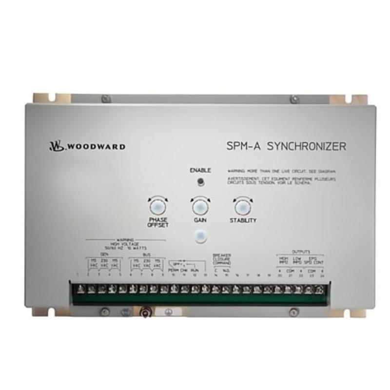
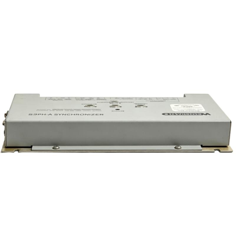
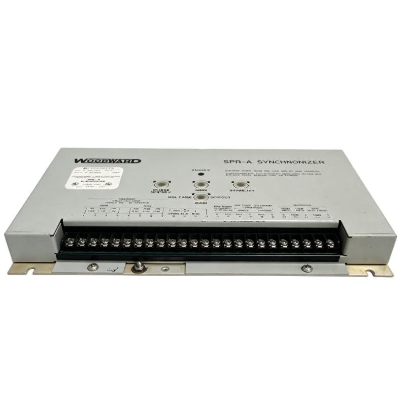
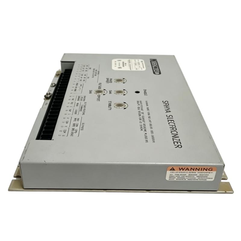
- Woodward
- 9907-029
- SPM-A Synchronizer
- USA
- 314.6 × 210.4 × 48.4 mm
- 2.67 kg
- Xiamen, China
- New & In Stock
- T/T, PayPal, Western Union
- 1 Year
- 1-3 Working Days
- DHL, UPS, TNT, FedEx and EMS.
- 24-Hour Service
- COO
- 4
Our advantage

Global Logistics
We have a 10-year logistics and express cooperation agreement, so our products can be shipped to any place in the world.

Brand new and original
Our products are imported in bulk from the place of origin. Because of the cooperative relationship, our products are all original and 100% new.

24-hour service
We provide 7*24 hours service to our customers. We will be there whenever you need us.

Price advantage
All our products are priced very favorably because we have our own warehouse and supply.
| Company Information | |||
| [email protected] | |||
| Mobile | +8615980777398 | ||
| +8615980777398 | |||
| 15980777398 |
Product Overview
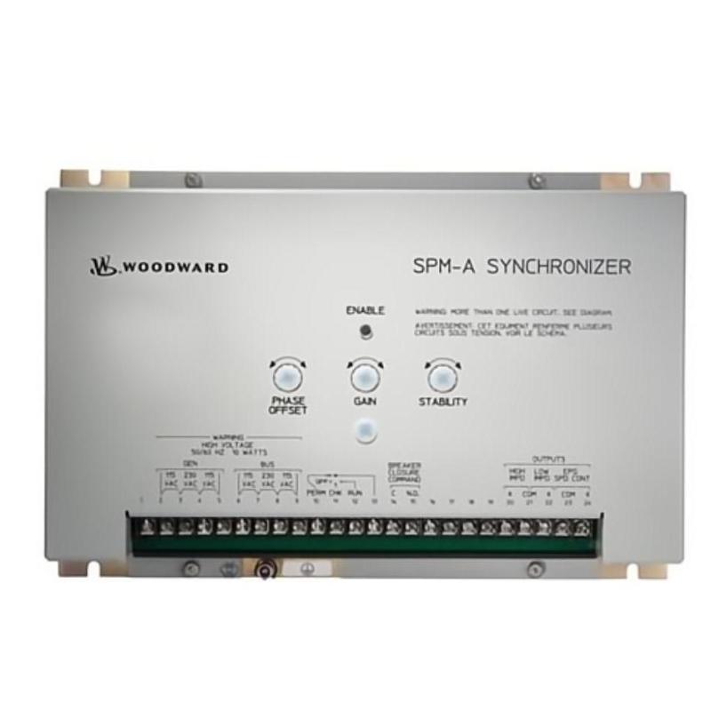
The Woodward 9907-029 SPM-A Synchronizer is an automatic synchronizing controller used to match an incoming generator’s frequency, phase angle, and voltage with an energized bus before the generator circuit breaker closes. It is intended for power-generation systems where generators must be connected in parallel under controlled electrical conditions.
When a standby generator starts, its electrical output must be brought into alignment with the operating bus before connection. A difference in frequency causes the phase angle to change continuously, while a voltage mismatch can produce an undesirable electrical transient at breaker closure. The 9907-029 addresses these conditions by coordinating speed correction and voltage matching through compatible external control equipment.
The SPM-A family supports integration with Woodward 2301 and 2301A load-sharing controls, as well as compatible electrically powered governors. The synchronizer sends speed-bias commands to the governing system and voltage-matching commands to the appropriate excitation-control interface. These external devices adjust the prime mover and generator excitation, allowing the incoming unit to approach the required synchronizing conditions.
The 9907-029 is the 50/60 Hz SPM-A configuration with a nominal ±10° phase-matching window and 1% voltage matching. This distinguishes it from the 9907-028, which provides speed and phase matching without automatic voltage matching. Selecting between these models therefore depends on whether voltage correction is required from the synchronizer or is handled by another part of the generator-control system.
In practical operation, the synchronizer is only one part of the paralleling sequence. The governor, automatic voltage regulator, voltage-sensing circuits, breaker-control circuit, and protective interlocks must work together. Correct configuration is essential when replacing an existing unit or commissioning a generator that will operate alongside other generating equipment.
Technical Specifications
| Parameter | Specification |
|---|---|
| Manufacturer | Woodward |
| Model / Part Number | 9907-029 |
| Product Family | SPM-A |
| Product Type | Speed and Phase Matching Synchronizer with Voltage Matching |
| Operating Frequency | 50/60 Hz |
| Generator and Bus Voltage Inputs | 115 or 230 V AC RMS |
| Input Voltage Tolerance | ±10% |
| Voltage Matching | 1% |
| Phase-Matching Window | ±10° |
| Maximum Power Consumption | 5 W |
| Operating Modes | RUN, CHECK, PERMISSIVE, OFF |
| Speed-Control Interface | Compatible high- or low-impedance output configuration |
| Breaker-Close Relay | Normally open contact |
| Breaker-Close Command Duration | Approximately 1 second |
| Match-Up Time Settings | 1/8, 1/4, 1/2, or 1 second |
| Mounting Arrangement | Back-panel mounting in switchgear |
| Operating Temperature | −45 to +70°C |
| Dimensions | 314.6 × 210.4 × 48.4 mm |
| Weight | 2.67 kg |
Product Features
- Automatic frequency matching: Sends speed-bias commands to a compatible governor to reduce the frequency difference between the incoming generator and the live bus.
- Phase-angle synchronization: Coordinates speed correction so that the incoming generator approaches the specified phase-matching window.
- 1% voltage matching: Supports correction of the incoming generator’s voltage through a compatible excitation or voltage-regulation interface.
- Selectable match-up time: Offers several internal timing selections to accommodate different prime-mover and generator responses.
- Multiple output configurations: Supports different governor and load-sharing interfaces through the appropriate output arrangement.
- Dedicated breaker-close relay: Provides a normally open contact for the configured breaker-closing circuit.
- Four operating modes: RUN, CHECK, PERMISSIVE, and OFF support automatic synchronization, testing, permissive operation, and shutdown of the synchronizing function.
- Automatic reset: Restores synchronizer availability according to the specified operating sequence after the generator disconnects from the bus.
- Adjustable control dynamics: Allows the synchronizing response to be configured for the characteristics of the connected prime mover and governing system.
Working Principle
The 9907-029 compares the electrical conditions of an incoming generator with those of an energized bus. It evaluates the voltage waveforms and their phase relationship, then coordinates frequency and voltage corrections through the connected governor and excitation-control equipment.
The basic synchronizing path is:
Incoming Generator and Live Bus → Voltage-Sensing Circuits → 9907-029 SPM-A → Governor and Voltage Regulator → Breaker-Close Circuit
The frequency-matching process begins when the synchronizer identifies a difference between the incoming generator frequency and the bus frequency. It sends a raise or lower speed-bias command to the compatible governing system. The governor adjusts prime-mover speed, changing generator frequency and controlling how quickly the phase angle moves toward the synchronizing window.
Voltage matching operates alongside frequency correction. When the incoming generator voltage differs from the bus voltage, the SPM-A provides a correction signal to the compatible voltage regulator or excitation-control interface. The objective is to bring the voltage difference within the required range before connection. The 1% voltage-matching specification identifies the matching capability of this model; actual system performance also depends on the regulator, sensing circuits, and commissioning settings.
The synchronizer also accounts for the configured match-up time. This setting determines how long the required synchronizing conditions must be maintained as part of the closing sequence. Since the breaker requires time to operate mechanically, the timing and phase window must be appropriate for the installation.
In RUN mode, the synchronizer can issue the breaker-close command when the configured conditions are met. CHECK mode allows synchronization and voltage matching to be evaluated without issuing the close command. PERMISSIVE mode provides a different operating arrangement in which the system’s synchronizing conditions can be checked without normal speed trimming or voltage matching. OFF disables the synchronizing function.
The 9907-029 does not independently regulate prime-mover speed or generator excitation. Those tasks remain with the connected governing and voltage-control systems. The synchronizer coordinates their responses, while breaker-control logic and the required protection devices determine whether closing is permitted.
Role in the Generator Synchronization Architecture
The 9907-029 occupies the synchronizing-control layer between electrical measurement circuits and the external governing, excitation, and breaker-control systems. Its purpose is to coordinate the conditions required for generator paralleling rather than replace the equipment responsible for speed regulation or electrical protection.
Generator and Bus Measurements → 9907-029 SPM-A → Governor and Voltage Regulator → Synchronizing Check → Generator Circuit Breaker
| System Component | Function |
|---|---|
| Woodward 9907-029 | Coordinates frequency, phase, and voltage matching |
| Incoming Generator | Supplies the electrical source being synchronized |
| Energized Bus | Provides the reference electrical conditions |
| Generator Voltage-Sensing Circuit | Measures the incoming generator voltage |
| Bus Voltage-Sensing Circuit | Provides the voltage reference for comparison |
| Governor or Load-Sharing Control | Adjusts prime-mover speed in response to speed-bias commands |
| Automatic Voltage Regulator | Adjusts excitation to control generator voltage |
| Breaker-Close Relay | Issues the synchronizer’s configured closing command |
| Generator Circuit Breaker | Connects the incoming generator to the energized bus |
| Synchronism-Check Relay | Provides additional closing supervision where required |
| Generator Protection System | Detects electrical faults and initiates protective action |
| Control Panel | Houses the synchronizer, interface wiring, and associated control equipment |
Industrial Applications
| Application | Typical Use |
|---|---|
| Diesel Generator Plants | Matching incoming generator frequency, phase, and voltage before paralleling |
| Gas Engine Power Stations | Coordinating governor and excitation corrections during synchronization |
| Standby Power Systems | Connecting additional generating capacity to an energized bus |
| Industrial Power Plants | Synchronizing generators operating in parallel |
| Combined Heat and Power Facilities | Coordinating generator entry into an existing plant electrical system |
| Remote Power Stations | Managing generator synchronization in isolated or local power networks |
| Multiple Generator Installations | Bringing individual generators onto a common bus |
| Data Center Power Systems | Supporting generator synchronization where parallel operation is required |
| Industrial Utility Systems | Integrating synchronizing control into generator switchgear |
| Generator Retrofit Projects | Replacing an SPM-A synchronizer while retaining compatible external controls |
Installation and Maintenance
- Verify the complete model reference: Confirm that the installed unit is 9907-029 and that the application requires the 50/60 Hz configuration with 1% voltage matching and a ±10° phase window.
- Check the voltage inputs: Verify that the generator and bus sensing circuits are configured for the applicable 115 or 230 V AC RMS input and remain within the specified voltage tolerance.
- Confirm phase connections: Check the generator and bus phase wiring, sensing polarity, and phase sequence against the installation drawings before enabling the synchronizer.
- Verify governor compatibility: Confirm that the selected output configuration matches the connected 2301, 2301A, EPG, or other supported governing arrangement.
- Check voltage-regulator integration: Verify that the excitation-control interface accepts the synchronizer’s voltage-matching signal and responds in the intended direction.
- Inspect breaker-control wiring: Check the normally open breaker-close relay connections, external control voltage, contact loading, and required electrical interlocks.
- Set the operating mode: Confirm that RUN, CHECK, PERMISSIVE, or OFF is selected according to the commissioning stage and the required control sequence.
- Review synchronizing adjustments: Verify the phase-matching window, voltage-matching function, match-up time, and control dynamics against the generator’s operating requirements.
- Inspect the control-panel installation: Check mounting security, terminal condition, conductor routing, and grounding arrangements before returning the equipment to service.
- Test without closing the breaker: Use CHECK mode to evaluate frequency correction, voltage matching, and phase alignment without issuing a breaker-close command.
- Validate the complete synchronizing sequence: Under an approved commissioning procedure, confirm that the governor and voltage regulator respond correctly and that breaker closure occurs only when the configured conditions are satisfied.
- Record the final configuration: Document the input voltage selection, governor interface, voltage-regulator connection, matching settings, operating mode, and commissioning results.
Compatible System Components
| Component | Function |
|---|---|
| Woodward 9907-029 SPM-A | Coordinates frequency, phase, and voltage matching |
| Woodward 2301 Load-Sharing Control | Supports compatible high-impedance synchronizer output arrangements |
| Woodward 2301A Load-Sharing and Speed Control | Supports compatible low-impedance output arrangements |
| Woodward Electrically Powered Governor (EPG) | Provides prime-mover speed control in supported configurations |
| Woodward 2500 Load-Sharing Control | Supports compatible synchronizer output configurations |
| Automatic Voltage Regulator | Adjusts generator excitation and voltage |
| Generator Voltage Transformer, Where Required | Provides the appropriate voltage-sensing level for the synchronizer |
| Bus Voltage-Sensing Circuit | Supplies the live-bus voltage reference |
| Generator Circuit Breaker | Connects the incoming generator to the bus |
| External Mode Selector Switch | Selects the synchronizer operating mode |
| Breaker-Control Circuit | Receives and processes the breaker-close command |
| Synchronism-Check Relay | Provides independent closing supervision where required |
Recommended Related Models
| Model | Product Type | Selection Consideration |
|---|---|---|
| Woodward 9907-029 | SPM-A Synchronizer with 1% Voltage Matching | 50/60 Hz operation, ±10° phase window, and 1% voltage matching |
| Woodward 9907-028 | SPM-A Speed and Phase Matching Synchronizer | Provides speed and phase matching without automatic voltage matching |
| Woodward 9905-003 | SPM-A Synchronizer with 5% Voltage Matching | Alternative voltage-matching specification with a ±10° phase window |
| Woodward 9905-004 | SPM-A Synchronizer without Voltage Matching | Uses a ±5° phase window without automatic voltage matching |
| Woodward 9905-005 | SPM-A Synchronizer with 1% Voltage Matching | Provides 1% voltage matching with a narrower ±5° phase window |
| Woodward 9905-006 | SPM-A Synchronizer with 0.5% Voltage Matching | Provides a different voltage-matching specification with a ±10° phase window |
| Woodward 2301A | Electronic Load-Sharing and Speed Control | Related governing and load-sharing control for compatible synchronizer interfaces |
Key Advantages
- Coordinates generator frequency, phase, and voltage matching before paralleling.
- Supports 50/60 Hz generator applications with a ±10° phase window.
- Provides a specified 1% voltage-matching function.
- Offers selectable match-up timing and adjustable synchronizing dynamics.
- Supports several governor and load-sharing control interfaces.
- Provides a dedicated breaker-close relay and multiple operating modes.
Technical FAQs
What is the specific synchronizing configuration of the 9907-029?
The 9907-029 is the SPM-A version intended for 50/60 Hz systems, with a ±10° phase-matching window and 1% voltage matching. These characteristics distinguish it from related SPM-A part numbers with different phase windows or voltage-matching specifications.
How does the synchronizer coordinate speed and voltage correction?
It sends speed-bias commands to a compatible governor and voltage-matching commands to a compatible excitation-control interface. The governor changes prime-mover speed, while the voltage regulator adjusts generator excitation; both responses are needed to bring the incoming generator into the required synchronizing range.
What does the match-up time setting change?
Match-up time determines the selected timing interval used in the synchronizing sequence. The SPM-A provides internal selections of 1/8, 1/4, 1/2, or 1 second. The correct setting depends on the generator response and breaker-closing requirements.
Why should the breaker-close relay be checked separately from the synchronizer settings?
The relay provides the closing command, but the external breaker circuit determines how that command reaches the breaker. Wiring, contact ratings, breaker operating characteristics, and required protection interlocks must all be verified to ensure that the closing sequence operates as intended.