

ProductPRODUCT
Featured products
Contact Us
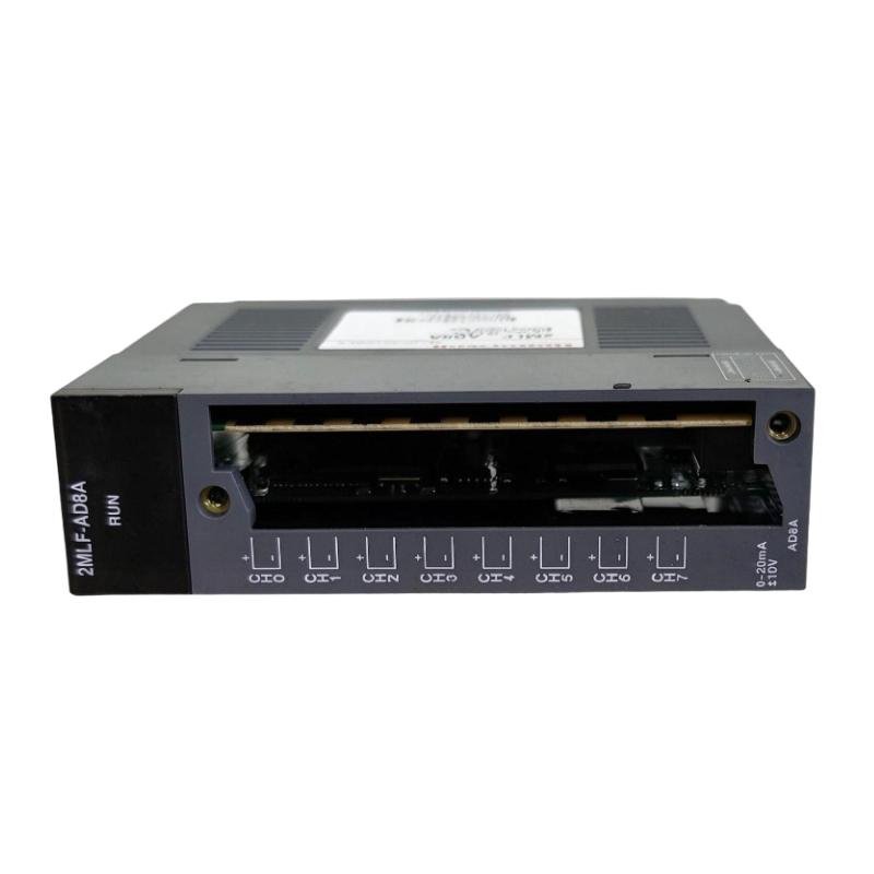
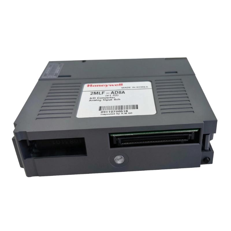
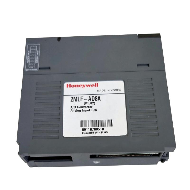
- Honeywell
- 2MLF-AD8A
- Analog/Digital Conversion Module
- USA
- 113 × 27 × 98 mm
- 0.14 kg
- Xiamen, China
- New & In Stock
- T/T, PayPal, Western Union
- 1 Year
- 1-3 Working Days
- DHL, UPS, TNT, FedEx and EMS.
- 24-Hour Service
- COO
- 7
Our advantage

Global Logistics
We have a 10-year logistics and express cooperation agreement, so our products can be shipped to any place in the world.

Brand new and original
Our products are imported in bulk from the place of origin. Because of the cooperative relationship, our products are all original and 100% new.

24-hour service
We provide 7*24 hours service to our customers. We will be there whenever you need us.

Price advantage
All our products are priced very favorably because we have our own warehouse and supply.
| Company Information | |||
| [email protected] | |||
| Mobile | +8615980777398 | ||
| +8615980777398 | |||
| 15980777398 |
Product Overview
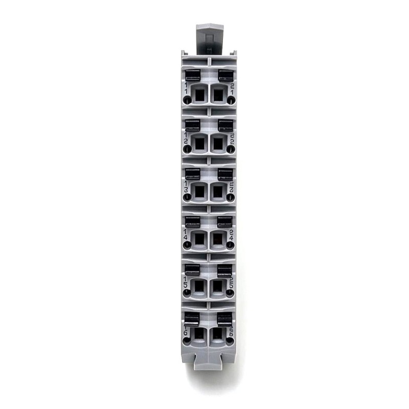
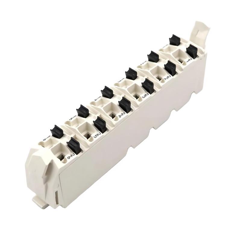
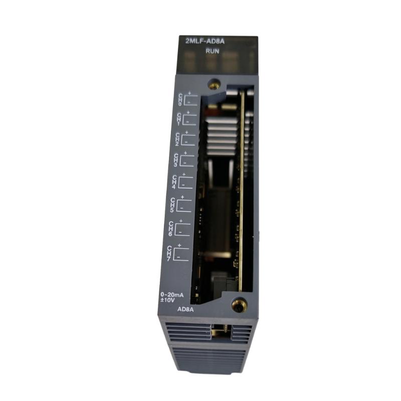
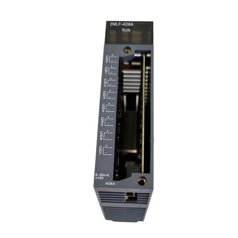
The Honeywell 2MLF-AD8A MasterLogic-200 Analog/Digital Conversion Module is an eight-channel analog input module that converts voltage and current signals from field instruments into digital values for processing by a programmable logic controller (PLC). It is used in MasterLogic-200 automation systems where multiple process measurements must be acquired and incorporated into machine or process control logic.
The module accepts a range of standard industrial analog signals, including voltage inputs from 1–5 V, 0–5 V, 0–10 V, and −10 to +10 V, as well as current inputs of 0–20 mA and 4–20 mA. This combination allows one module type to accommodate different instrument outputs without requiring separate voltage-only and current-only input hardware.
In a process control panel, for example, the 2MLF-AD8A can acquire signals from pressure transmitters, flow instruments, level sensors, and other devices with compatible analog outputs. The PLC converts the acquired values into engineering units and uses them for monitoring, alarm evaluation, interlocking, or closed-loop control according to the application program.
The module provides a specified digital resolution of 1/16,000 and a conversion speed of 250 μs per channel. Its accuracy is specified at ±0.2% or less under reference ambient conditions of 25 ± 5°C. These characteristics make it suitable for many conventional industrial measurement tasks where multiple analog variables must be processed by a single controller.
Input ranges and digital data formats must be configured correctly for the connected instruments. A voltage transmitter connected to a channel configured for current input, for example, will not produce a correctly interpreted measurement. Commissioning therefore involves both electrical verification and confirmation of the PLC’s scaling parameters.
Technical Specifications
| Parameter | Specification |
|---|---|
| Manufacturer | Honeywell |
| Model / Part Number | 2MLF-AD8A |
| Product Family | MasterLogic-200 |
| Product Type | Analog/Digital Conversion Module |
| Module Function | Analog-to-Digital Conversion |
| Number of Analog Input Channels | 8 |
| Input Signal Types | Voltage and current |
| Voltage Input Ranges | 1–5 V, 0–5 V, 0–10 V, −10 to +10 V DC |
| Current Input Ranges | 0–20 mA, 4–20 mA |
| Digital Resolution | 1/16,000 |
| Conversion Speed | 250 μs per channel |
| Conversion Accuracy at 25 ± 5°C | ±0.2% or less |
| Conversion Accuracy at 0–55°C | ±0.3% or less |
| Maximum Input Voltage | ±15 V |
| Maximum Input Current | ±30 mA |
| Voltage Input Resolution | 0.250 mV at 1–5 V; 0.3125 mV at 0–5 V; 0.625 mV at 0–10 V; 1.250 mV at −10 to +10 V |
| Current Input Resolution | 1.0 μA at 4–20 mA; 1.25 μA at 0–20 mA |
| Digital Data Formats | Signed, precise, percentile, and 14-bit binary representations |
| Terminal Connection | 32-point terminal |
| Occupied I/O Points | 64 fixed points or 16 variable points |
| Internal Current Consumption | 330 mA at 5 V DC |
| Operating Ambient Temperature | 0–55°C |
| Storage Temperature | −25 to +70°C |
| Dimensions | 113 × 27 × 98 mm |
| Weight | 0.14 kg |
Product Features
- Eight configurable analog input channels: Acquires multiple voltage or current signals through a single module, reducing the need for separate input modules for different signal types.
- Wide selection of input ranges: Supports four standard voltage ranges and two current ranges for integration with compatible industrial transmitters.
- 1/16,000 digital resolution: Provides detailed digital representation of the measured analog signal for PLC processing.
- 250 μs conversion per channel: Supports relatively fast acquisition of process measurements, with the overall control response also depending on the PLC scan and application logic.
- Specified conversion accuracy: Offers accuracy of ±0.2% or less at 25 ± 5°C and ±0.3% or less over the stated 0–55°C ambient range.
- Multiple digital data formats: Supports signed, precise, percentile, and 14-bit binary representations for different application requirements.
- Configurable I/O parameters: Allows operating parameters to be established through the supported PLC engineering environment, reducing the need to implement every configuration task directly in the sequence program.
- Compact PLC integration: Fits into the MasterLogic-200 modular control architecture for centralized acquisition of field measurements.
- Defined electrical input limits: Specifies maximum input levels of ±15 V and ±30 mA, which are important when evaluating wiring errors and potential overrange conditions.
Working Principle
The 2MLF-AD8A converts continuous electrical signals from field instruments into digital values that the MasterLogic-200 CPU can process. Each channel measures the incoming voltage or current according to its configured input range, and the conversion result is made available to the PLC program.
A typical measurement path is:
Field Transmitter → Analog Signal Wiring → 2MLF-AD8A → Digital Measurement Value → PLC Application
Consider a pressure transmitter that produces a 4–20 mA signal. The transmitter changes its output current according to the measured pressure, and the 2MLF-AD8A converts that current into a digital representation. The PLC then applies the configured scaling to calculate the pressure in engineering units.
For a voltage-output instrument, the same process applies using the selected voltage range. A transmitter producing 0–10 V, for example, requires the corresponding input configuration and matching program scaling. The module cannot determine the intended engineering units from the electrical signal alone.
The digital representation depends on the selected data format. In signed mode, the input is represented using a signed value. Precise mode uses values associated with the selected measurement range, while percentile mode represents the measurement on a normalized scale. The 14-bit binary format provides another supported representation. The PLC program must interpret the chosen format correctly to avoid incorrect readings or control decisions.
The module’s specified conversion speed is 250 μs per channel. This is the conversion time associated with an individual channel, not a guarantee that the complete control system responds within the same period. The PLC scan cycle, instrument response, filtering, and application logic also affect the time between a physical process change and the resulting control action.
The 2MLF-AD8A performs analog acquisition and conversion; it does not independently control valves, motors, or other actuators. Those actions depend on the CPU program and the corresponding output hardware.
Role in the MasterLogic-200 PLC Architecture
The 2MLF-AD8A occupies the analog acquisition layer between field instrumentation and the PLC processor. It supplies digital measurement data that can be used by control routines, operator displays, alarms, and process calculations.
Field Instruments → 2MLF-AD8A Analog Input Module → MasterLogic-200 CPU → Control Logic → Output Modules → Actuators
| System Component | Function |
|---|---|
| Honeywell 2MLF-AD8A | Converts eight voltage or current input signals into digital values |
| MasterLogic-200 CPU | Executes the application program and processes acquired measurements |
| Compatible PLC Base | Provides the module mounting and electrical interface |
| Pressure Transmitters | Supply electrical signals representing process pressure |
| Flow Transmitters | Provide analog measurements of process flow |
| Level Transmitters | Supply signals representing tank or vessel level |
| Temperature Transmitters | Provide voltage or current signals representing temperature |
| Analog Output Modules | Supply configured analog commands to compatible control devices |
| Digital I/O Modules | Acquire discrete states and control digital outputs |
| Engineering Software | Supports module configuration, program development, and diagnostics |
| Operator Interface | Displays process measurements and alarm states when configured |
The eight input channels allow several instruments to be acquired by one module. The final allocation of channels depends on the required signal types, field wiring arrangement, and the control program’s measurement and scaling requirements.
Industrial Applications
| Application | Typical Use |
|---|---|
| Water and Wastewater Treatment | Acquiring pressure, flow, and tank-level measurements |
| Chemical Processing | Collecting analog signals from process transmitters |
| Pumping Stations | Monitoring discharge pressure, flow, and reservoir levels |
| Manufacturing Lines | Acquiring process variables used in machine sequencing and interlocks |
| Packaging Machinery | Reading analog feedback from compatible sensors and instruments |
| Boiler and Utility Systems | Monitoring pressure and other variables through supported transmitters |
| Food and Beverage Processing | Acquiring flow and level measurements for process monitoring |
| Oil and Gas Facilities | Connecting compatible current- and voltage-output instruments |
| Process Skids | Consolidating several analog measurements within one PLC module |
| Industrial Equipment Monitoring | Feeding process data into PLC calculations, alarms, and operator displays |
Installation and Maintenance
- Verify the module reference: Confirm that the installed module is 2MLF-AD8A and that the application requires eight voltage/current input channels.
- Check PLC compatibility: Verify the MasterLogic-200 CPU, base, and module configuration before installing or replacing the unit.
- Identify the field signals: Record each connected instrument, its output type, its nominal range, and the engineering units expected by the PLC program.
- Configure the input ranges: Set each channel to the appropriate voltage or current range before commissioning the field instruments.
- Inspect the terminal connections: Check the wiring, terminal assignments, conductor condition, and polarity where applicable before applying power.
- Check the electrical limits: Ensure that the connected signal remains within the specified maximum input voltage of ±15 V or maximum input current of ±30 mA, as applicable.
- Configure the digital format: Select the required signed, precise, percentile, or 14-bit binary representation and confirm that the application interprets the selected format correctly.
- Review the grounding and shielding: Follow the panel design and instrument-wiring requirements to reduce interference and avoid unwanted ground-current paths.
- Check the backplane power budget: Include the module’s 330 mA consumption at 5 V DC when calculating the load on the PLC’s internal supply.
- Validate the measurements: Apply known input signals or compare readings against suitable reference instruments to confirm channel operation and scaling.
- Investigate abnormal values: Check the field transmitter, wiring, configured range, data format, and PLC scaling if readings are unstable, out of range, or inconsistent with the process.
- Record commissioning details: Document channel assignments, input ranges, data formats, scaling values, test results, and any changes made during maintenance.
Compatible System Components
| Component | Function |
|---|---|
| Honeywell MasterLogic-200 CPU | Processes the digital values supplied by the input module |
| Compatible MasterLogic-200 Base | Provides the physical and electrical interface for the module |
| Voltage-Output Transmitters | Supply supported voltage signals for measurement |
| Current-Output Transmitters | Supply 0–20 mA or 4–20 mA signals |
| Pressure Transmitters | Convert pressure into a compatible electrical signal |
| Flow Transmitters | Provide process-flow measurements |
| Level Transmitters | Supply vessel or tank-level signals |
| Temperature Transmitters | Provide temperature measurements using supported voltage or current outputs |
| Analog Output Modules | Supply analog commands to compatible actuators |
| Digital I/O Modules | Handle discrete signals and control functions |
| Engineering Software | Supports module settings and PLC application development |
| Instrument Wiring and Terminal Assemblies | Connect field signals to the module’s input terminals |
Recommended Related Models
| Model | Product Type | Main Difference |
|---|---|---|
| Honeywell 2MLF-AD8A | Analog/Digital Conversion Module | Eight voltage/current input channels |
| Honeywell 2MLF-AD16A | Analog/Digital Conversion Module | Sixteen voltage/current input channels |
| Honeywell 2MLF-AD4S | Isolated Analog Input Module | Four voltage/current input channels with channel isolation |
| Honeywell 2MLF-AV8A | Voltage Analog Input Module | Eight voltage input channels |
| Honeywell 2MLF-AC8A | Current Analog Input Module | Eight current input channels |
| Honeywell 2MLF-AC4H | HART Analog Input Module | Four current input channels with HART support |
| Honeywell 2MLF-DC4A | Analog Output Module | Four current output channels |
| Honeywell 2MLF-DV4A | Analog Output Module | Four voltage output channels |
Key Advantages
- Acquires eight voltage or current signals through one module.
- Supports common industrial voltage ranges and 0–20 mA or 4–20 mA current loops.
- Provides a specified digital resolution of 1/16,000.
- Offers a conversion speed of 250 μs per channel.
- Supports multiple digital data formats for PLC processing.
- Integrates with the modular MasterLogic-200 control architecture.
Technical FAQs
Can voltage and current transmitters be connected to the same 2MLF-AD8A module?
The module supports both voltage and current input types across its eight channels. Each channel must be configured for the appropriate signal range, and the wiring must follow the corresponding terminal arrangement. The selected digital format and program scaling must also match the connected instrument.
What is the practical difference between 1/16,000 resolution and ±0.2% accuracy?
Resolution describes the granularity of the digital measurement representation, while accuracy describes how closely the measured value corresponds to the actual input under the specified test conditions. High resolution does not, by itself, guarantee an equally small measurement error.
Does the 250 μs conversion time determine the PLC’s complete response time?
No. It describes the module’s specified conversion time per channel. The complete response also depends on the PLC scan cycle, instrument response, configured filtering, communication between system components, and the execution of the control program.
What should be checked when a 4–20 mA transmitter produces an incorrect PLC value?
Check the selected current range, terminal wiring, actual loop current, digital data format, and engineering-unit scaling. If the electrical signal is correct but the displayed value is not, review the PLC program’s conversion and scaling calculations before replacing the module.