

ProductPRODUCT
Featured products
Contact Us
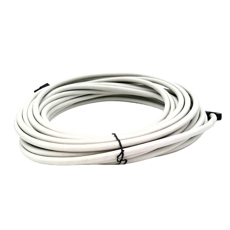
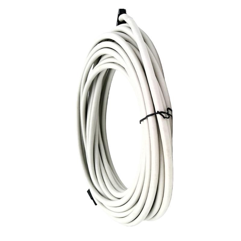
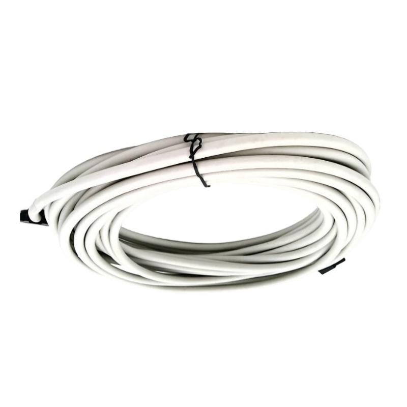
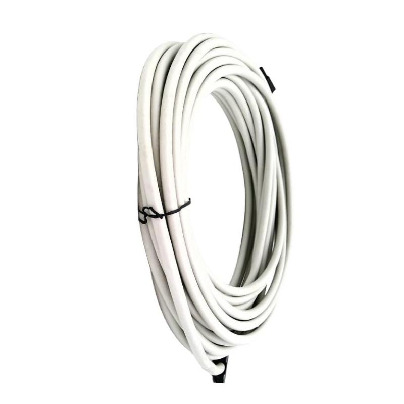
- Honeywell
- 2MLC-E501
- Extension Cable
- USA
- 5 meters
- 3 kg
- Xiamen, China
- New & In Stock
- T/T, PayPal, Western Union
- 1 Year
- 1-3 Working Days
- DHL, UPS, TNT, FedEx and EMS.
- 24-Hour Service
- COO
- 4
Our advantage

Global Logistics
We have a 10-year logistics and express cooperation agreement, so our products can be shipped to any place in the world.

Brand new and original
Our products are imported in bulk from the place of origin. Because of the cooperative relationship, our products are all original and 100% new.

24-hour service
We provide 7*24 hours service to our customers. We will be there whenever you need us.

Price advantage
All our products are priced very favorably because we have our own warehouse and supply.
| Company Information | |||
| [email protected] | |||
| Mobile | +8615980777398 | ||
| +8615980777398 | |||
| 15980777398 |
Product Overview
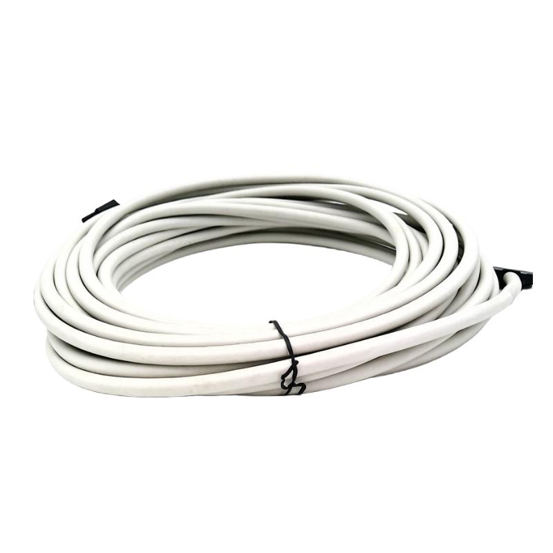
The Honeywell 2MLC-E501 MasterLogic-200 Extension Cable is an expansion I/O cable used to connect compatible expansion bases in the MasterLogic-200 programmable logic controller (PLC) system. It supports installations built around the 2MLI-CPUU architecture, where additional I/O bases are required to accommodate the field signals used by a machine or process.
In a distributed control cabinet, the main CPU base may handle the central control program while an expansion base accommodates additional digital and analog I/O modules. The 2MLC-E501 provides the dedicated connection between compatible hardware, allowing the PLC system to accommodate a broader cabinet layout without concentrating every I/O module on the main base.
The 5-meter cable length is useful when expansion hardware must be positioned farther from the CPU base than shorter cable options allow. This can help accommodate cabinet layouts with separated mounting sections or equipment arrangements that require additional routing distance. The complete expansion path must remain within the applicable system limit.
For example, a production line may use the main PLC base for sequence control and an expansion base for additional photoelectric sensors, valve feedback, and motor-status signals. The 2MLC-E501 can connect the expansion hardware when the required cable route suits its length and the system configuration supports the connection.
The 2MLC-E501 is a dedicated MasterLogic-200 accessory, not a general-purpose communication lead. Its selection should account for the CPU model, expansion-base arrangement, connector compatibility, and total distance between the CPU and the farthest expansion base.
Technical Specifications
| Parameter | Specification |
|---|---|
| Manufacturer | Honeywell |
| Model / Part Number | 2MLC-E501 |
| Product Family | MasterLogic-200 |
| Product Type | Expansion I/O Cable |
| Compatible CPU Configuration | 2MLI-CPUU-based expansion arrangement |
| Cable Length | 5 meters |
| Shipping Weight | 3 kg |
Product Features
- Dedicated expansion connection: Connects compatible MasterLogic-200 expansion hardware within the supported I/O architecture.
- 5-meter cable length: Accommodates expansion layouts requiring more reach than the shorter cable variants.
- System-specific application: Intended for the designated expansion-I/O connection rather than general-purpose signal wiring.
- Distributed I/O arrangement: Supports installations that place additional I/O modules on separate expansion bases.
- Multiple length options: Belongs to a cable family covering several connection distances for different system layouts.
- Model-specific identification: The 2MLC-E501 reference distinguishes the 5-meter version during installation and spare-parts selection.
Working Principle
The 2MLC-E501 establishes the physical connection between compatible MasterLogic-200 CPU-base and expansion-base hardware. It carries the signals required for the connected expansion arrangement to operate within the supported PLC architecture.
A typical configuration follows this path:
MasterLogic-200 CPU and Main Base → 2MLC-E501 Extension Cable → I/O Expansion Base → Installed I/O Modules
The CPU executes the application program, while the installed I/O modules acquire field signals or provide control outputs. The expansion cable connects the additional base so that its supported I/O modules can participate in the programmed control sequence.
Consider a material-handling system in which the main base handles the operating sequence and an expansion base collects additional sensor inputs and actuator feedback. The extension cable connects the designated hardware, allowing the PLC application to use those signals without requiring every module to be installed on the main base.
Cable selection must account for the complete expansion route. For the applicable MasterLogic-200 arrangement, the total distance between the CPU and the farthest I/O expansion base must not exceed 15 meters. A 5-meter cable therefore needs to be considered alongside any other cable sections in the same path.
The 2MLC-E501 does not execute control logic, convert analog signals, or function as an independent network switch. Its role is to provide the required physical interconnection between compatible expansion-system components.
Role in the MasterLogic-200 PLC Architecture
The 2MLC-E501 occupies the interconnection layer between the main PLC hardware and an expansion base. It supports a modular I/O arrangement in which additional field connections can be located away from the CPU base.
PLC CPU and Main Base → Expansion Cable → Expansion Base → Digital and Analog I/O Modules
| System Component | Function |
|---|---|
| Honeywell 2MLC-E501 | Connects compatible expansion-system hardware |
| MasterLogic-200 CPU | Executes the PLC program and coordinates control operations |
| Main CPU Base | Hosts the CPU and supported main-base modules |
| I/O Expansion Base | Provides additional positions for I/O modules |
| Digital Input Modules | Acquire discrete signals from sensors and switches |
| Digital Output Modules | Control compatible field devices through designated output circuits |
| Analog Input Modules | Acquire supported process measurements |
| Analog Output Modules | Supply configured analog control signals |
| Field Devices | Provide sensor feedback or receive control commands |
| Control Cabinet | Houses the PLC bases, modules, and associated wiring |
Industrial Applications
| Application | Typical Use |
|---|---|
| Packaging Machinery | Connecting expansion bases for additional sensors and actuators |
| Conveyor Systems | Extending I/O capacity for motor feedback and position switches |
| Assembly Lines | Linking expansion bases serving separate machine stations |
| Material Handling | Connecting expansion hardware for equipment status and interlocks |
| Process Control Panels | Extending the PLC’s field-signal capacity |
| Water Treatment Systems | Connecting additional I/O for pumps, valves, and instrumentation |
| Manufacturing Equipment | Incorporating additional control points into an existing PLC arrangement |
| Industrial Utility Systems | Connecting compatible expansion bases in utility-control cabinets |
| Machine-Building Projects | Accommodating separated expansion hardware within the planned layout |
| PLC Retrofit Projects | Reconnecting supported expansion hardware during control-panel modifications |
Installation and Maintenance
- Verify the model reference: Confirm that the required cable is 2MLC-E501 and that its 5-meter length suits the intended expansion connection.
- Check hardware compatibility: Identify the MasterLogic-200 CPU and expansion-base models before installing the cable.
- Review the cabinet layout: Confirm that the cable reaches both connection points without excessive tension or interference with cabinet doors and other equipment.
- Isolate the equipment: Follow the approved PLC shutdown and electrical isolation procedure before disconnecting or installing the cable.
- Inspect the connectors: Check both ends for damaged contacts, contamination, or mechanical deformation.
- Plan the cable route: Avoid crushing, sharp bends, abrasion, and contact with moving equipment or sharp cabinet edges.
- Verify the connection points: Match both ends to the designated interfaces in the system installation documentation.
- Secure the cable arrangement: Route and support the cable so that its connectors are not subjected to unnecessary mechanical stress.
- Check the total expansion distance: Confirm that the complete CPU-to-farthest-expansion-base cable route remains within the applicable 15-meter limit.
- Restore the system: Reassemble the cabinet and restore power according to the approved commissioning procedure.
- Verify expansion operation: Confirm that the PLC recognizes the connected expansion hardware and that the installed I/O modules operate as expected.
- Record the installation: Document the cable model, connected base references, and results of the post-installation checks.
Compatible System Components
| Component | Function |
|---|---|
| Honeywell MasterLogic-200 CPU | Executes the PLC application |
| Honeywell MasterLogic-200 Main Base | Hosts the CPU and supported main-base modules |
| Honeywell MasterLogic-200 Expansion Base | Provides additional I/O module positions |
| Digital Input Modules | Acquire discrete field signals |
| Digital Output Modules | Provide discrete control outputs |
| Analog Input Modules | Acquire process-variable signals |
| Analog Output Modules | Supply analog commands to compatible field devices |
| Control Cabinet Wiring | Connects the PLC system to field equipment |
| Honeywell 2MLC-E501 | Provides the 5-meter expansion connection |
Recommended Related Models
| Model | Product Type | Cable Length |
|---|---|---|
| Honeywell 2MLC-E041 | MasterLogic-200 Expansion I/O Cable | 0.4 m |
| Honeywell 2MLC-E061 | MasterLogic-200 Expansion I/O Cable | 0.6 m |
| Honeywell 2MLC-E121 | MasterLogic-200 Expansion I/O Cable | 1.2 m |
| Honeywell 2MLC-E301 | MasterLogic-200 Expansion I/O Cable | 3.0 m |
| Honeywell 2MLC-E501 | MasterLogic-200 Expansion I/O Cable | 5.0 m |
| Honeywell 2MLC-E102 | MasterLogic-200 Expansion I/O Cable | 10.0 m |
| Honeywell 2MLC-E152 | MasterLogic-200 Expansion I/O Cable | 15.0 m |
Key Advantages
- Connects compatible MasterLogic-200 expansion hardware.
- Provides a 5-meter connection option for layouts requiring additional reach.
- Supports additional PLC I/O capacity through compatible expansion bases.
- Simplifies identification during installation and spare-parts replacement.
- Offers an alternative to shorter cables while retaining the system’s expansion-distance requirements.
Technical FAQs
Which CPU configuration is associated with the 2MLC-E501?
The 2MLC-E501 is listed for the MasterLogic-200 expansion I/O arrangement associated with the 2MLI-CPUU. Check the installed CPU and base configuration before selecting the cable for a replacement or system extension.
How does the 2MLC-E501 differ from the 2MLC-E301?
The 2MLC-E501 is 5.0 meters long, while the 2MLC-E301 is 3.0 meters long. The choice depends on the required routing distance and the total cable length permitted by the expansion arrangement.
Can a 5-meter cable be used when several expansion bases are installed?
It can be considered where the hardware arrangement supports the connection, but the complete route must be evaluated. For the applicable MasterLogic-200 configuration, the total distance from the CPU to the farthest I/O expansion base must not exceed 15 meters.
What should be checked if an expansion base is unavailable after the cable is installed?
Inspect both connectors, verify the cable is correctly seated, and check the CPU and expansion-base configuration. Also review the PLC’s expansion status and confirm that the complete cable arrangement follows the system requirements.