

ProductPRODUCT
Featured products
Contact Us
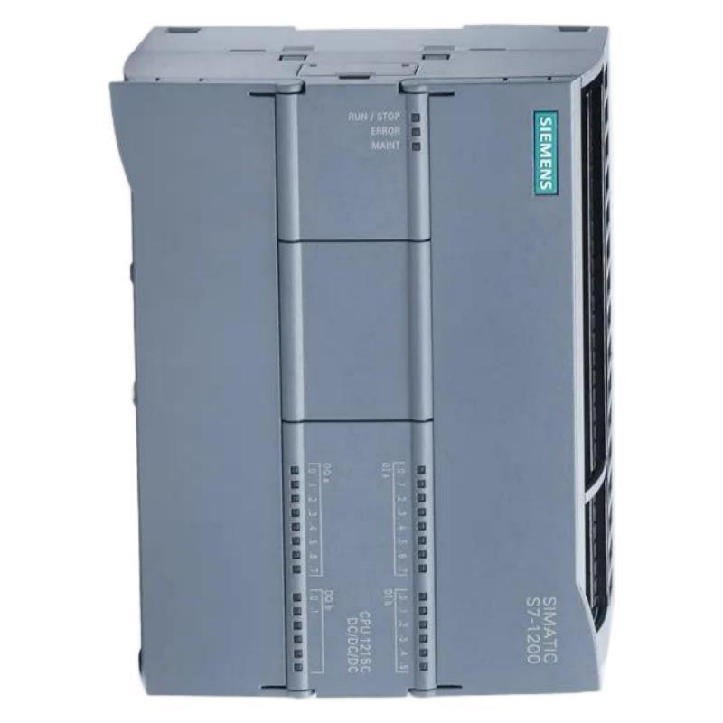
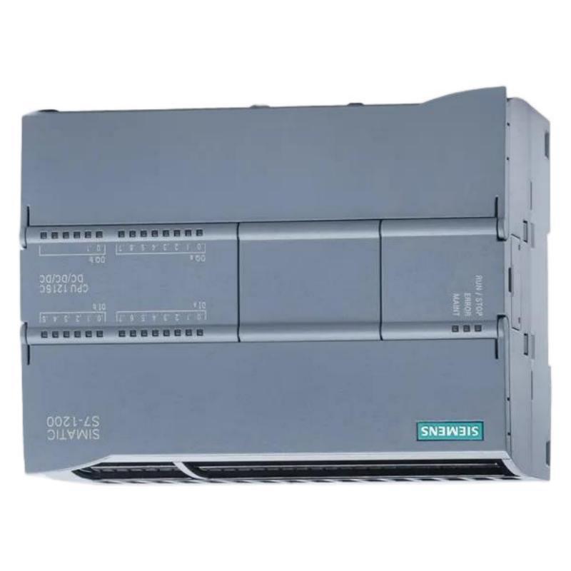
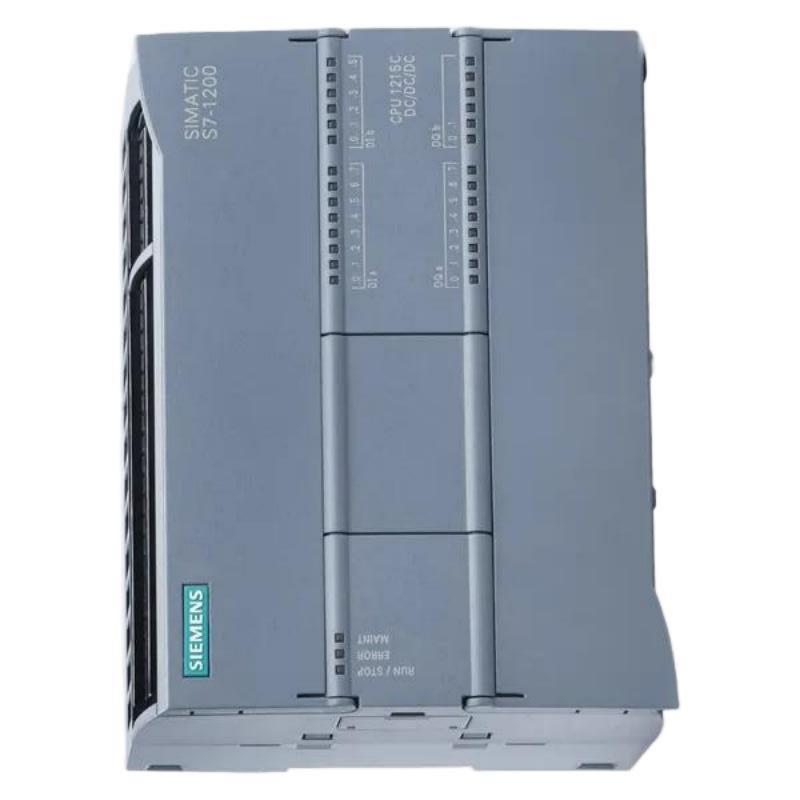
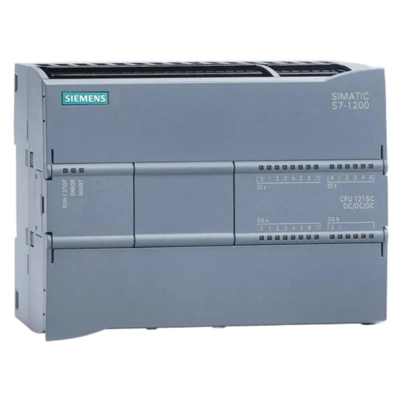
- Siemens
- 6AG1215-1BG40-4XB0
- Central Processing Unit
- Germany
- 130 × 100 × 75 mm
- 0.55 kg
- Xiamen, China
- New & In Stock
- T/T, PayPal, Western Union
- 1 Year
- 1-3 Working Days
- DHL, UPS, TNT, FedEx and EMS.
- 24-Hour Service
- COO
- 5
Our advantage

Global Logistics
We have a 10-year logistics and express cooperation agreement, so our products can be shipped to any place in the world.

Brand new and original
Our products are imported in bulk from the place of origin. Because of the cooperative relationship, our products are all original and 100% new.

24-hour service
We provide 7*24 hours service to our customers. We will be there whenever you need us.

Price advantage
All our products are priced very favorably because we have our own warehouse and supply.
| Company Information | |||
| [email protected] | |||
| Mobile | +8615980777398 | ||
| +8615980777398 | |||
| 15980777398 |
Product Overview
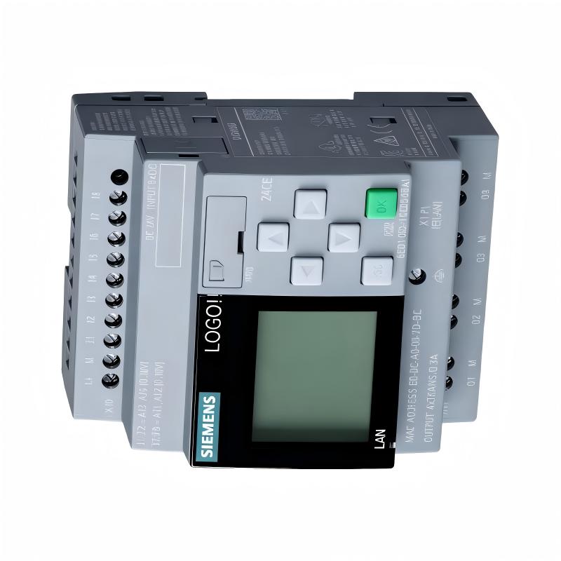
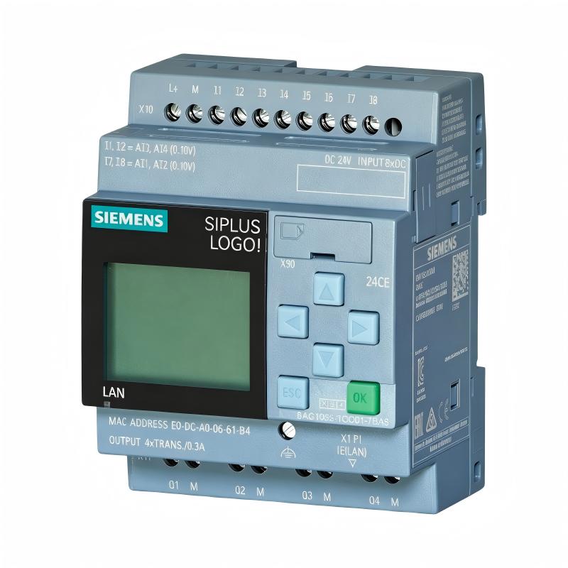
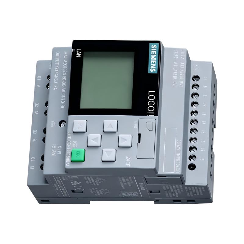
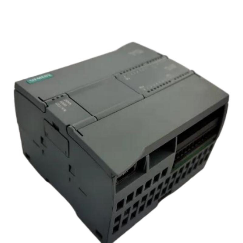
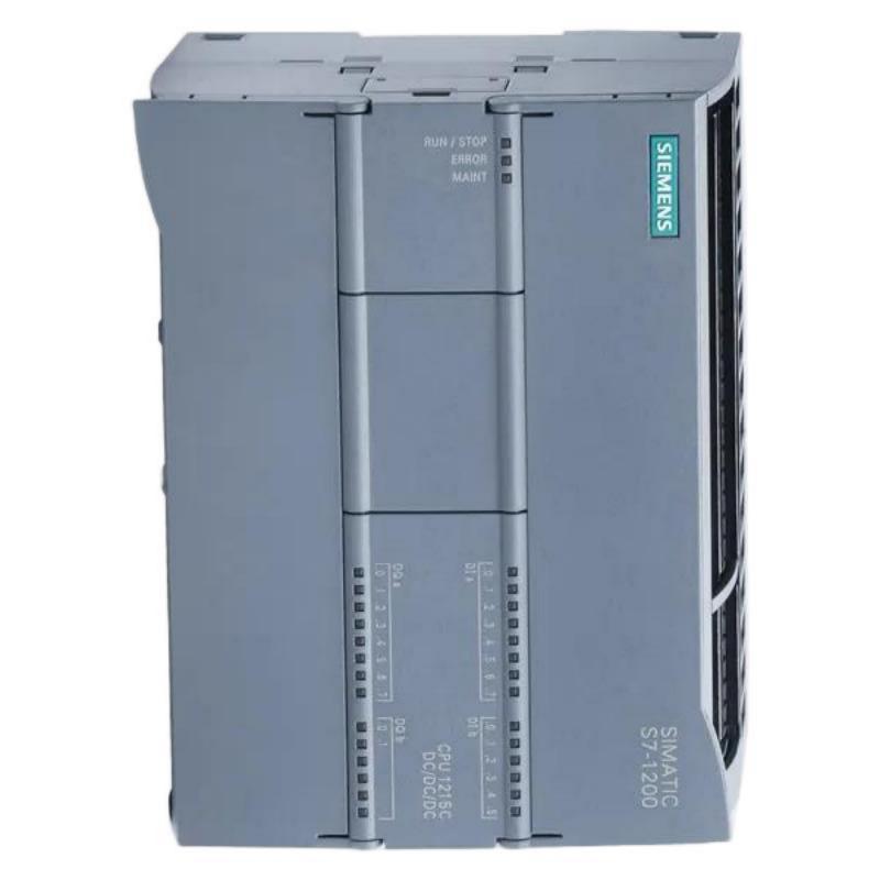
The Siemens 6AG1215-1BG40-4XB0 Central Processing Unit is a PLC processing component designed to serve as the central control element within a compatible industrial automation system. As the processing core of a programmable controller, the CPU executes application logic, evaluates process information, manages internal data, and coordinates connected input, output, communication, and operator-interface components.
With listed dimensions of 130 × 100 × 75 mm and a weight of 0.55 kg, the 6AG1215-1BG40-4XB0 provides a compact form factor for industrial control cabinets and modular automation installations. Its physical design allows it to be incorporated into control systems where reliable processing and efficient cabinet utilization are important considerations.
A PLC CPU typically operates as part of a complete automation architecture rather than as a standalone device. Sensors and field instruments provide process information, I/O equipment transfers that information to the controller, the CPU executes the programmed control strategy, and output devices respond to the resulting commands.
The exact memory resources, communication capabilities, firmware functions, integrated interfaces, and supported modules associated with the 6AG1215-1BG40-4XB0 should be confirmed for the specific hardware configuration before engineering or replacement work.
Technical Specifications
| Parameter | Specification |
|---|---|
| Manufacturer | Siemens |
| Model | 6AG1215-1BG40-4XB0 |
| Product Type | Central Processing Unit |
| Product Function | PLC Central Processing and Control |
| Application | Industrial Automation |
| System Role | Main Controller / Processing Unit |
| Dimensions | 130 × 100 × 75 mm |
| Weight | 0.55 kg |
| Installation | Industrial Control Cabinet / PLC System |
| Control Function | Program Execution and Process Control |
| Data Processing | PLC Logic and Application Data |
| I/O Integration | Compatible PLC I/O Architecture |
| Communication | Dependent on exact hardware configuration |
| Memory | Verify according to specific hardware version |
| Firmware | Verify according to installed hardware revision |
| Programming | Compatible Siemens PLC Engineering Environment |
Understanding the 6AG1215-1BG40-4XB0
The Siemens 6AG1215-1BG40-4XB0 functions as the central processing element of a compatible programmable automation controller.
In an industrial control application, numerous devices continuously generate information. Sensors may detect position, temperature, pressure, flow, level, speed, or equipment status. The CPU receives the corresponding process information through the configured I/O architecture and executes the application logic programmed by the automation engineer.
The resulting commands can be transmitted to output devices controlling:
- Motors
- Valves
- Contactors
- Solenoids
- Indicators
- Pneumatic equipment
- Production machinery
- Auxiliary equipment
This creates a structured relationship between the physical process and the programmed control strategy.
A simplified architecture is:
Field Devices → I/O System → CPU → Control Logic → Output System → Equipment
The CPU therefore acts as the decision-making and processing center of the PLC system.
Core Processing and Control Functions
The primary purpose of a central processing unit is to execute the automation program and coordinate the operation of the connected control system.
Typical CPU responsibilities include:
- Executing application logic
- Processing input information
- Updating output states
- Managing internal variables
- Performing calculations
- Handling timers and counters
- Evaluating interlocks
- Managing operating sequences
- Processing diagnostic information
- Coordinating communication
- Managing machine states
A well-structured PLC program allows the CPU to control complex equipment through repeatable sequences.
For example, a machine may require a motor to start only after several permissive conditions have been satisfied. The CPU can evaluate sensor signals, equipment status, operator commands, and interlocking conditions before generating the motor-start command.
This type of logic provides controlled and predictable machine operation.
PLC Operating Cycle
The CPU operates through a continuous control process.
Input Evaluation
Process information is obtained from connected field devices and input modules. Signals may represent equipment status, operator commands, sensor states, or measured process values.
Logic Processing
The CPU executes the programmed control logic. This may involve sequence control, comparisons, timers, counters, mathematical calculations, interlocks, and alarm conditions.
Output Updating
After the relevant logic has been processed, output information is updated for connected output devices.
Communication and Diagnostics
The controller may also handle communication and diagnostic operations associated with the automation system.
This repeated processing cycle allows the CPU to respond continuously to changing machine and process conditions.
Role in Industrial Control Architecture
The 6AG1215-1BG40-4XB0 can form the central layer between field-level devices and higher-level automation functions.
A typical industrial control system may contain:
Sensors and Instruments
↓
Input Modules
↓
PLC CPU
↓
Output Modules / Communication Interfaces
↓
Actuators and Industrial Equipment
↓
HMI / Supervisory Monitoring
The CPU coordinates the exchange of information between these different layers.
For example, in a material-handling system, photoelectric sensors may detect products entering different conveyor sections. The CPU processes these signals and determines when motors or actuators should operate.
In a process system, the controller can evaluate process conditions and execute programmed sequences according to defined operating parameters.
Industrial Applications
The Siemens 6AG1215-1BG40-4XB0 can be used as part of compatible PLC architectures serving a wide range of industrial applications.
Manufacturing Automation
Production equipment frequently requires coordinated control of sensors, motors, actuators, and machine sequences. A central CPU provides the processing platform for this control logic.
Conveyor and Material Handling
Conveyor systems use PLC logic to control motor operation, product detection, routing, accumulation, and equipment interlocking.
Packaging Machinery
Packaging systems require coordinated timing and sequencing between sensors, drives, actuators, and machine stations.
Assembly Systems
Automated assembly equipment can use PLC processing to coordinate positioning, clamping, detection, and machine sequencing.
Pumping Systems
Industrial pumping equipment can use PLC control for start/stop commands, permissive conditions, alarm monitoring, and operating sequences.
Process Equipment
Process skids and auxiliary industrial equipment may use PLC controllers to manage automated sequences and equipment status.
Utility Systems
Industrial utility installations can incorporate PLC-based control for equipment such as ventilation, water handling, compressed-air systems, and other mechanical infrastructure.
I/O and Peripheral Integration
A CPU normally operates together with other automation components.
Depending on the system architecture, these may include:
| Component | Function |
|---|---|
| Digital Input Module | Receives discrete field signals |
| Digital Output Module | Controls discrete devices |
| Analog Input Module | Receives process measurements |
| Analog Output Module | Sends analog control signals |
| Communication Module | Exchanges data with external equipment |
| HMI | Provides operator visualization |
| Industrial Network | Connects automation devices |
| Sensors | Detect process conditions |
| Actuators | Perform physical actions |
| Drives | Control motor operation |
The exact compatible modules and interfaces should be confirmed against the installed PLC platform and hardware configuration.
This is especially important when planning an expansion or replacing an existing CPU.
Communication and Automation Networking
Modern industrial automation systems often require continuous data exchange between controllers, I/O stations, HMIs, drives, and supervisory equipment.
Communication functions can support:
- Remote I/O data exchange
- Controller-to-controller communication
- HMI data exchange
- Drive control
- Diagnostic information
- Process monitoring
- Production data transfer
- System status reporting
The exact communication interfaces and supported protocols for the 6AG1215-1BG40-4XB0 should be verified from the specific hardware documentation and configuration.
Communication requirements should be considered during the initial system design because network compatibility can affect CPU selection and replacement planning.
Program Execution and Automation Logic
The CPU executes the application program developed for the machine or process.
A typical automation program can contain:
- Start and stop sequences
- Automatic operating modes
- Manual operating modes
- Safety-related permissive logic
- Equipment interlocks
- Alarm processing
- Timer functions
- Counter functions
- Product tracking
- Motor control sequences
- Process monitoring
- Fault handling
The program can also manage internal process data used by the control system.
For example, a production machine may maintain information about machine state, production count, operating mode, equipment status, and alarm conditions.
Exact memory capacity and processing characteristics should not be assumed from a related CPU model; they should be confirmed for the 6AG1215-1BG40-4XB0 hardware version being used.
Installation Guide
Correct installation is important for reliable operation of any industrial PLC CPU.
Verify the Product Identification
Before installation, confirm the complete part number:
Siemens 6AG1215-1BG40-4XB0
The ordering number should match the engineering documentation and existing equipment records.
Check Physical Space
The listed dimensions are:
130 × 100 × 75 mm
Cabinet planning should allow sufficient additional space for wiring, connectors, ventilation, neighboring modules, and maintenance access.
Prepare the Control Cabinet
The CPU should be installed inside an appropriate industrial control enclosure that provides suitable environmental protection.
The installation environment should be controlled to minimize exposure to:
- Excessive dust
- Moisture
- High temperatures
- Vibration
- Mechanical impact
- Electrical interference
Verify Mechanical Installation
The CPU and associated modules should be mounted securely according to the applicable system installation procedure.
Improper mounting can result in connector stress, mechanical instability, or maintenance difficulties.
Check Electrical Connections
Before applying power, inspect:
- Power connections
- Grounding
- Module connections
- Communication connections
- Network cables
- Connector seating
- Field wiring
A systematic inspection can prevent many startup problems.
Commissioning Procedure
After installation, the CPU should be commissioned in a controlled sequence.
1. Inspect the Hardware
Confirm that the CPU and all associated modules are correctly installed.
2. Verify Power
Check the control-system power supply and confirm that the installed equipment receives the required supply conditions.
3. Check Hardware Configuration
Verify that the configured hardware corresponds to the actual physical installation.
4. Load the Application
Transfer the correct PLC application program and associated configuration to the controller using the approved engineering environment.
5. Review Diagnostic Status
Check CPU and system diagnostic information before putting the machine into automatic operation.
6. Test Inputs
Activate field devices individually and confirm that the CPU receives the expected input states.
7. Test Outputs
Verify the operation of output devices under controlled conditions.
8. Test Interlocks
Confirm that equipment cannot operate outside the intended sequence.
9. Test Automatic Operation
Run the machine through its normal operating sequence while monitoring system status.
10. Record Commissioning Results
Document the final program version, hardware configuration, network settings, and commissioning results.
Troubleshooting the Siemens 6AG1215-1BG40-4XB0
When diagnosing a PLC problem, it is important to determine whether the CPU is actually defective or whether the problem originates elsewhere in the automation system.
CPU Will Not Operate
Possible causes can include:
- Power supply problems
- Incorrect wiring
- Loose connectors
- Hardware configuration errors
- Associated module faults
- CPU hardware problems
Start by verifying power and physical connections before replacing the processor.
Communication Problems
If another device cannot exchange data with the CPU, inspect:
- Communication cables
- Network connections
- Device configuration
- Addressing
- Network status
- Configuration consistency
- Connected equipment
A network problem should not automatically be interpreted as a CPU failure.
Incorrect Machine Sequence
Unexpected machine behavior may result from:
- Incorrect application logic
- Wrong parameter values
- Incorrect input signals
- Output mapping errors
- Faulty field sensors
- Communication problems
- Incorrect hardware configuration
Monitoring the actual input and output states can help distinguish a program problem from a hardware problem.
Output Does Not Respond
Follow the complete control path:
Field Condition → Input → CPU Logic → Output → Actuator
If the input is correct but the programmed output does not change, inspect the application logic and configuration.
If the CPU generates the expected output but the equipment does not respond, inspect the output module, wiring, actuator, and field equipment.
Intermittent Operation
Intermittent faults can be caused by:
- Loose connections
- Electrical noise
- Unstable power
- Damaged cables
- Vibration
- Temperature changes
- Faulty field devices
Recording the timing and operating conditions of intermittent faults can help identify the underlying cause.
Preventive Maintenance
A preventive maintenance program can help maintain long-term PLC system reliability.
Inspect Connections
Check CPU connectors, module connections, terminals, and network cables for looseness or physical damage.
Maintain Cabinet Cleanliness
Dust accumulation can interfere with thermal management and increase the risk of equipment problems.
Monitor Environmental Conditions
Control cabinet temperature, humidity, vibration, and contamination should remain within the requirements of the installed automation equipment.
Maintain Application Backups
Maintain current backups of:
- PLC programs
- Hardware configuration
- Parameters
- Network configuration
- HMI projects
- Engineering documentation
Review Diagnostic Information
Regularly review available system diagnostics to identify developing hardware or communication problems.
Replacement and Compatibility Considerations
When replacing a 6AG1215-1BG40-4XB0, matching physical dimensions alone is not sufficient.
The following should be verified:
- Complete Siemens ordering number
- Hardware revision
- Firmware requirements
- Application program
- Hardware configuration
- Communication requirements
- Connected I/O modules
- Network configuration
- Memory requirements
- Existing parameter settings
The replacement unit should be compared against the original CPU and system documentation before installation.
The listed physical dimensions are:
130 × 100 × 75 mm
The listed weight is:
0.55 kg
These specifications are useful for cabinet layout, transportation, inventory management, and replacement planning.
Cabinet Layout Considerations
The compact CPU dimensions can simplify cabinet planning, but engineers should allow more space than the basic product dimensions alone.
Additional space may be needed for:
- Power wiring
- Communication cables
- Module connections
- Ventilation
- Cable bending radius
- Maintenance access
- Module removal
- Adjacent equipment
Cable routing should also be planned so that power conductors and sensitive communication or signal wiring are appropriately separated.
Good cabinet organization makes future troubleshooting and maintenance easier.
Fault Diagnosis Strategy
A structured troubleshooting method can significantly reduce unnecessary component replacement.
A practical diagnostic sequence is:
Power → CPU Status → Hardware Configuration → Communication → Inputs → Program Logic → Outputs → Field Equipment
First verify the power supply and CPU operating condition.
Next confirm that the hardware configuration matches the physical system.
Then inspect communication and I/O status.
After confirming that the input information is correct, evaluate the application logic.
Finally, check output behavior and the connected field equipment.
This approach helps isolate faults systematically instead of replacing the CPU without sufficient evidence.
Engineering and Maintenance Best Practices
For systems using the Siemens 6AG1215-1BG40-4XB0, several practices can improve maintainability.
Keep Hardware Documentation Updated
Record the exact CPU model, installed modules, wiring configuration, and network structure.
Maintain Program Version Control
Store the current PLC application and configuration with clear version identification.
Label Connections
Proper labeling of power, communication, and field wiring makes maintenance more efficient.
Keep a Spare Strategy
For critical production systems, maintaining suitable spare hardware can reduce downtime following an unexpected failure.
Verify Before Replacement
Always compare the full product designation rather than selecting a replacement based only on dimensions or physical appearance.
Document Modifications
Any hardware, software, or configuration changes should be recorded after commissioning.
Key Advantages
The Siemens 6AG1215-1BG40-4XB0 provides several useful characteristics for industrial PLC applications:
- Centralized PLC processing
- Compact 130 × 100 × 75 mm dimensions
- Listed weight of 0.55 kg
- Suitable for control cabinet installation
- Supports programmed automation sequences
- Coordinates information between field devices and control logic
- Suitable for modular PLC architectures
- Supports structured system diagnostics
- Practical for industrial machine and process control applications
- Can form part of larger Siemens automation systems when correctly configured
Technical FAQs
What is the Siemens 6AG1215-1BG40-4XB0?
The Siemens 6AG1215-1BG40-4XB0 is a Central Processing Unit used as the main processing and control element within a compatible PLC-based automation system.
What are the dimensions of the 6AG1215-1BG40-4XB0?
The listed dimensions are 130 × 100 × 75 mm.
What is the weight of the 6AG1215-1BG40-4XB0?
The listed weight is approximately 0.55 kg.
What does a PLC central processing unit do?
A PLC CPU executes the programmed control logic, processes input information, manages internal data, and generates commands for connected automation equipment.
Can the CPU be used for machine automation?
A compatible PLC system incorporating this CPU can be used for machine automation, material handling, process equipment, and other industrial control applications, depending on the complete system configuration.
What should be checked before installing the CPU?
The complete ordering number, hardware configuration, firmware compatibility, connected modules, power requirements, communication requirements, and application program should be checked.
What causes PLC communication failures?
Communication problems can result from incorrect configuration, network wiring issues, addressing errors, incompatible devices, cable damage, or faults in connected equipment.
Why is a PLC program backup important?
A current program and configuration backup makes it easier to restore the automation system after CPU replacement, configuration problems, or unexpected hardware failure.
Can another 130 × 100 × 75 mm CPU be used as a replacement?
Not automatically. Physical dimensions do not establish electrical, firmware, communication, or system compatibility. The complete ordering number and system requirements must be verified.
How should the CPU be maintained?
Maintenance should include inspection of connections, control cabinet conditions, communication wiring, system diagnostics, and application backups. The surrounding PLC system should also be checked periodically.
Conclusion
The Siemens 6AG1215-1BG40-4XB0 Central Processing Unit is a central PLC processing component intended to coordinate programmed control functions within a compatible industrial automation architecture. It provides the processing layer between field information, application logic, I/O equipment, communication systems, and controlled machinery.
The listed dimensions of 130 × 100 × 75 mm and weight of 0.55 kg provide useful reference values for control cabinet design, inventory management, transportation, and replacement planning.
In an industrial application, reliable operation depends on more than the CPU itself. Correct hardware configuration, stable power, properly installed I/O equipment, reliable communication, accurate application programming, suitable cabinet conditions, and systematic diagnostics all contribute to dependable automation performance.
For installation or replacement of the 6AG1215-1BG40-4XB0, engineers and maintenance personnel should verify the complete product designation and system configuration before commissioning. Exact memory resources, communication interfaces, firmware functions, integrated features, and supported modules should be confirmed for the specific hardware version rather than assumed from similar Siemens CPU models.