

ProductPRODUCT
Featured products
Contact Us
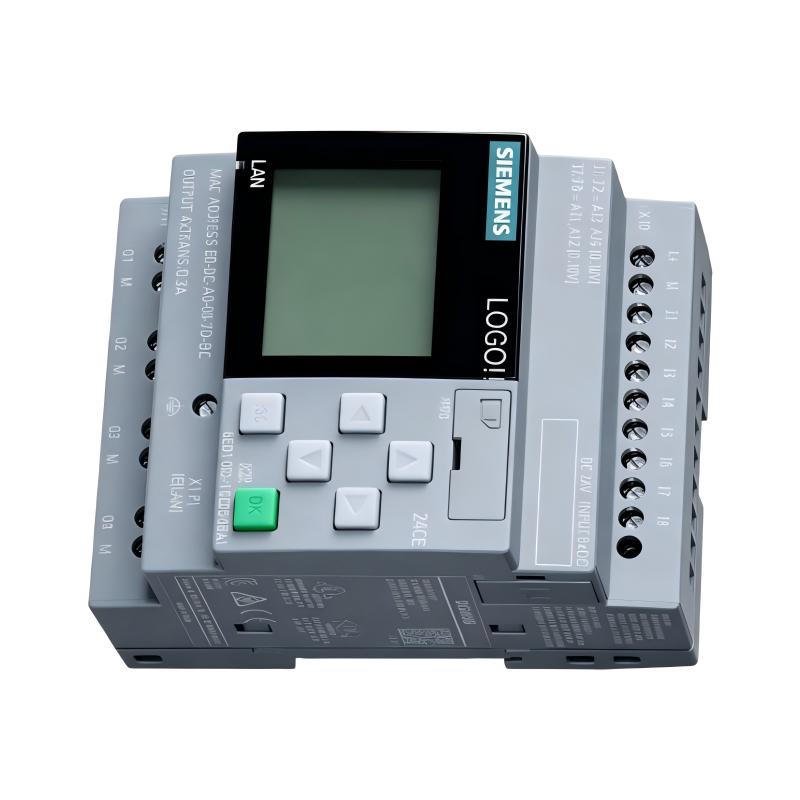
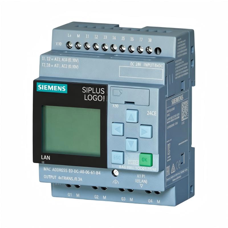
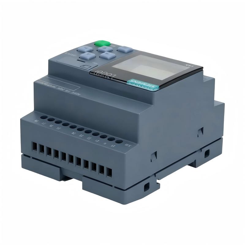
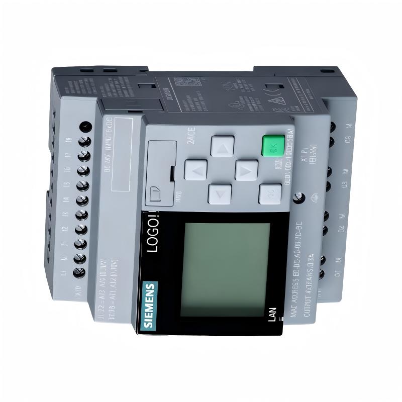
- Siemens
- 6AG1052-1FB08-7BA0
- Logic Module
- Germany
- 71.5 x 90 x 60 mm
- 0.25 kg
- Xiamen, China
- New & In Stock
- T/T, PayPal, Western Union
- 1 Year
- 1-3 Working Days
- DHL, UPS, TNT, FedEx and EMS.
- 24-Hour Service
- COO
- 4
Our advantage

Global Logistics
We have a 10-year logistics and express cooperation agreement, so our products can be shipped to any place in the world.

Brand new and original
Our products are imported in bulk from the place of origin. Because of the cooperative relationship, our products are all original and 100% new.

24-hour service
We provide 7*24 hours service to our customers. We will be there whenever you need us.

Price advantage
All our products are priced very favorably because we have our own warehouse and supply.
| Company Information | |||
| [email protected] | |||
| Mobile | +8615980777398 | ||
| +8615980777398 | |||
| 15980777398 |
Product Overview
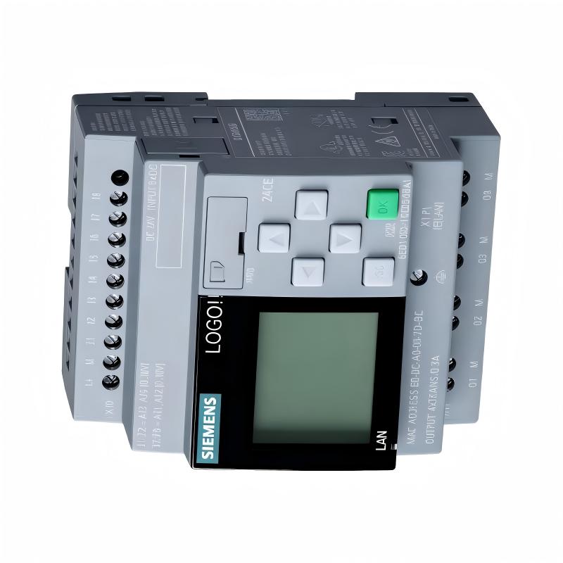
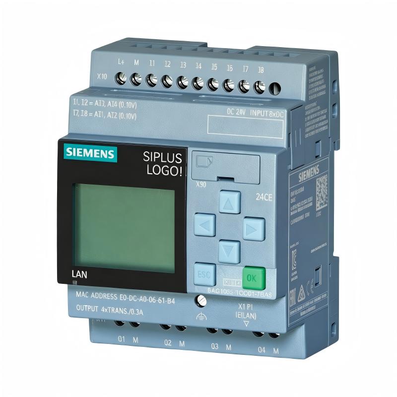
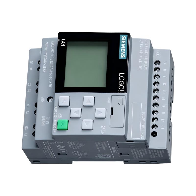
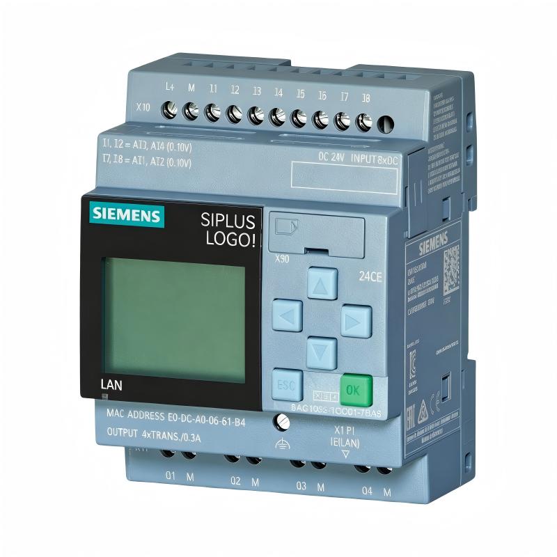
The Siemens 6AG1052-1FB08-7BA0 Logic Module is a compact programmable control device designed for implementing logic functions in industrial automation and electrical control applications. It provides a practical solution for applications that require localized programmable control without necessarily requiring the full hardware structure of a larger PLC system.
With listed dimensions of 71.5 × 90 × 60 mm and a weight of 0.25 kg, the 6AG1052-1FB08-7BA0 is suitable for compact control cabinets, machine control panels, equipment automation assemblies, and distributed control installations where available space must be used efficiently.
Logic modules are commonly used to replace or simplify conventional combinations of relays, timers, switches, and other discrete control elements. By implementing control logic electronically, the system can provide structured sequencing, condition monitoring, switching decisions, timing functions, and equipment interlocking.
The exact input/output configuration, electrical ratings, communication capabilities, memory characteristics, programming functions, and environmental specifications should be confirmed against the applicable configuration of the 6AG1052-1FB08-7BA0 before engineering or installation.
Technical Specifications
| Parameter | Specification |
|---|---|
| Manufacturer | Siemens |
| Model | 6AG1052-1FB08-7BA0 |
| Product Type | Logic Module |
| Primary Function | Programmable logic and localized automation control |
| Dimensions | 71.5 × 90 × 60 mm |
| Weight | 0.25 kg |
| Installation | Industrial control cabinet / automation equipment |
| Application | Machine control, sequencing, monitoring and equipment automation |
| Control Method | Programmable logic-based control |
| System Integration | Siemens industrial automation architecture, subject to configuration |
| Physical Design | Compact control module |
The dimensions and weight above are the product information supplied for this article. Exact electrical and functional characteristics should be verified for the installed hardware before connecting field equipment.
What Is the Siemens 6AG1052-1FB08-7BA0?
The 6AG1052-1FB08-7BA0 is a Siemens Logic Module intended to provide programmable control functionality in industrial automation environments.
A logic module evaluates defined conditions and performs programmed actions according to the control sequence. Instead of using a large number of individual hardwired components, a programmable logic device can consolidate multiple control functions into one compact electronic unit.
A simplified automation sequence can be represented as:
Field Inputs → Logic Processing → Control Decision → Output Command → Machine Response
Inputs can represent equipment states, operator commands, sensor conditions, or other control signals. The logic function evaluates these conditions and determines whether the associated output or control action should occur.
This architecture is particularly useful when a machine or subsystem contains repetitive and clearly defined logical operations.
Logic Module Operating Concept
The operating principle of a programmable logic module is based on evaluating input conditions and executing programmed control instructions.
A typical control sequence may include:
- Receiving an input condition.
- Evaluating programmed logic.
- Checking permissive conditions.
- Applying timing or sequence requirements.
- Determining the required output state.
- Sending the control command.
- Monitoring subsequent operating conditions.
This type of control makes it possible to create repeatable machine sequences while reducing the amount of physical relay wiring.
The exact programming environment and available logic functions for the 6AG1052-1FB08-7BA0 should be confirmed for the specific hardware configuration.
Role in Industrial Automation
Compact logic controllers are useful when automation functions need to be handled locally.
A larger industrial system may contain:
- Central PLC controllers
- Remote I/O stations
- HMIs
- Sensors
- Motor starters
- Variable speed drives
- Contactors
- Solenoid valves
- Safety equipment
- Industrial communication systems
Within this architecture, a logic module can provide localized control for a specific machine, utility system, or equipment group.
The control structure can be organized as:
Sensors and Switches → Logic Module → Local Equipment
while higher-level systems can supervise the overall operation.
This separation can make the automation system easier to organize and can reduce the need to route every simple control signal through a central controller.
Industrial Applications
Machine Automation
The Siemens 6AG1052-1FB08-7BA0 can be considered for machine-control architectures where programmed logical sequences are required.
Typical operations can include:
- Start and stop sequences
- Equipment enable conditions
- Reset logic
- Interlocking
- Operating-state selection
- Alarm conditions
- Sequence control
The actual application must be matched to the module’s confirmed capabilities.
Conveyor Control
Conveyor systems frequently require logical coordination between motors, sensors, and machine sections.
A logic-based control architecture can coordinate conditions such as:
- Start commands
- Stop commands
- Product detection
- Equipment readiness
- Interlocks
- Fault conditions
Pump and Utility Systems
Local control logic can also be useful for pumps and utility equipment.
A programmed sequence may evaluate equipment availability, operating conditions, start commands, and fault signals before permitting operation.
Packaging Equipment
Packaging machinery often requires repeated control sequences involving multiple machine states. A programmable logic device can help organize these operations where the hardware is suitable for the application.
Material Handling Systems
Material-handling systems can use localized logic for equipment sequencing, sensor-based switching, and coordination between machine sections.
Programmable Control and Sequencing
One of the main benefits of programmable logic is that control behavior can be changed through configuration rather than extensive rewiring.
For example, a machine-start sequence could operate as follows:
Start Command
↓
Check Permissive Conditions
↓
Confirm Required Equipment Status
↓
Execute Programmed Logic
↓
Activate Control Output
↓
Monitor Equipment Response
↓
Continue or Stop Sequence
This approach provides a structured method for implementing repeatable automation sequences.
For safety-related functions, dedicated safety hardware and the overall safety architecture must be used where required. A general-purpose logic module should not automatically be treated as a safety controller.
Installation and Cabinet Planning
The 6AG1052-1FB08-7BA0 has listed dimensions of:
71.5 × 90 × 60 mm
and a listed weight of:
0.25 kg
These values should be included when planning the control cabinet layout.
Before installation, engineers should evaluate:
- Available mounting space
- Device orientation
- Cable routing
- Terminal access
- Adjacent modules
- Cabinet ventilation
- Environmental conditions
- Grounding arrangements
- Maintenance accessibility
The compact size can be advantageous in installations where several automation components must share limited cabinet space.
Electrical Installation Considerations
The logic module should be installed according to the electrical requirements of the actual device configuration.
Important considerations include:
Power Supply
The correct supply voltage and connection arrangement must be confirmed before energizing the device.
Input Connections
Field input devices must be electrically compatible with the module’s actual input configuration.
Typical field devices may include:
- Pushbuttons
- Selector switches
- Proximity sensors
- Limit switches
- Level switches
- Status contacts
The actual supported input characteristics should be verified before connection.
Output Connections
Logic outputs may control external devices such as:
- Relays
- Contactors
- Indicator devices
- Solenoid valves
- Control interfaces
The connected load must remain within the confirmed electrical capabilities of the output circuit.
Grounding and Noise
Proper grounding and cable routing can help reduce electrical interference and improve signal reliability.
System Integration
The 6AG1052-1FB08-7BA0 can form part of a larger industrial automation system.
A typical architecture may contain:
| Component | Typical Function |
|---|---|
| Sensors | Detect process or machine conditions |
| Logic Module | Executes programmed control logic |
| PLC | Coordinates broader automation functions |
| HMI | Provides operator control and visualization |
| Relays | Provide switching or interface functions |
| Contactors | Control electrical equipment |
| Drives | Control motor operation |
| Actuators | Perform physical actions |
| SCADA | Provides supervisory monitoring |
The exact role of the logic module depends on the control architecture and the functions required by the application.
Commissioning Procedure
A structured commissioning process helps prevent wiring and configuration problems from becoming operational faults.
1. Verify the Model
Confirm the device identification:
Siemens 6AG1052-1FB08-7BA0
Do not rely only on physical appearance when identifying replacement equipment.
2. Inspect the Installation
Check mounting, wiring, connectors, cabinet conditions, and surrounding equipment.
3. Verify Power
Confirm the supply arrangement before applying power.
4. Check Input Devices
Test connected switches and sensors individually where possible.
5. Verify Program Logic
Confirm that the programmed sequence corresponds to the intended machine operation.
6. Test Outputs
Operate output functions under controlled conditions and verify the response of connected equipment.
7. Test Interlocks
Check all required permissive and interlocking conditions before enabling automatic operation.
8. Run the Complete Sequence
Perform a controlled operational test and confirm that the machine responds correctly at each stage.
Troubleshooting the Siemens 6AG1052-1FB08-7BA0
Troubleshooting should begin with the complete control path rather than assuming that the logic module is defective.
The basic diagnostic path is:
Power → Input → Logic → Output → Field Device
Logic Module Does Not Start
Possible causes include:
- Incorrect power connection
- Power supply problem
- Loose wiring
- Incorrect installation
- Hardware fault
- Configuration issue
The power and installation should be checked first.
Input Condition Is Not Recognized
If an expected input is not recognized, inspect:
- Field sensor
- Switch condition
- Wiring
- Terminal connections
- Signal compatibility
- Configuration
- External power supply
A failed sensor can produce symptoms that resemble a controller problem.
Output Does Not Respond
If the logic appears correct but the equipment does not respond, inspect:
- Output configuration
- Program conditions
- Interlocks
- Output wiring
- External power
- Relay or contactor
- Connected load
The fault may be located downstream from the logic module.
Machine Sequence Is Incorrect
Unexpected operation can result from:
- Incorrect program logic
- Incorrect input state
- Wiring errors
- Missing permissive conditions
- Incorrect configuration
- Faulty field equipment
Reviewing the control sequence step by step is often more effective than replacing components immediately.
Preventive Maintenance
Preventive maintenance helps maintain stable operation of compact control equipment.
Recommended activities include:
- Inspect terminal connections.
- Check wiring for mechanical damage.
- Keep the control cabinet clean.
- Inspect for signs of overheating.
- Check for moisture or contamination.
- Verify connectors are properly seated.
- Maintain current configuration backups.
- Record model and hardware information.
- Monitor recurring control faults.
Because logic modules are part of a larger control chain, preventive maintenance should also include connected sensors, relays, contactors, and actuators.
Configuration and Program Backup
Control configuration is an important part of maintaining a programmable automation system.
Before replacing a logic module, maintenance personnel should determine whether the existing application configuration or program needs to be transferred to the replacement device.
Recommended practices include:
- Maintain a current backup.
- Record configuration versions.
- Document important machine settings.
- Keep replacement procedures available.
- Record hardware identification.
- Verify the restored configuration before production operation.
A replacement hardware unit alone does not necessarily reproduce the complete control behavior of the original installation.
Replacement Considerations
When replacing the Siemens 6AG1052-1FB08-7BA0, the complete order number should be checked carefully.
Important information includes:
- Full model number
- Hardware version
- Existing configuration
- Wiring arrangement
- Connected field devices
- Control program
- Application requirements
- Cabinet installation arrangement
The listed physical specifications are:
Dimensions: 71.5 × 90 × 60 mm
Weight: 0.25 kg
These values can be used for cabinet planning and spare-parts logistics.
A visually similar Siemens logic module should not automatically be considered an interchangeable replacement. Functional compatibility must be confirmed before installation.
Cabinet Space and Mechanical Design
Compact control components can provide significant advantages when many devices must be installed inside one cabinet.
For the 6AG1052-1FB08-7BA0, the listed dimensions of 71.5 × 90 × 60 mm should be considered together with:
- Wiring space
- Cable bend radius
- Adjacent components
- Service access
- Ventilation
- Terminal accessibility
- Future expansion
The module’s listed weight of 0.25 kg also provides a useful reference for handling and equipment-layout calculations.
Diagnostic Approach for Industrial Control Systems
A systematic troubleshooting method can reduce unnecessary component replacement.
When the machine does not operate as expected, engineers can divide the system into several stages:
Stage 1 — Power
Confirm that the required supply is present and stable.
Stage 2 — Field Inputs
Verify that switches and sensors provide the expected signals.
Stage 3 — Logic Processing
Determine whether the programmed conditions are being evaluated correctly.
Stage 4 — Outputs
Confirm that the required control outputs are being generated.
Stage 5 — Field Equipment
Check relays, contactors, drives, valves, motors, or other connected equipment.
Stage 6 — Process Response
Verify that the controlled equipment produces the expected physical result.
This approach helps distinguish between a logic-module fault and problems elsewhere in the automation system.
Key Advantages
The Siemens 6AG1052-1FB08-7BA0 Logic Module offers several practical characteristics for compact industrial control applications:
- Compact 71.5 × 90 × 60 mm form factor
- Listed weight of 0.25 kg
- Programmable logic-based control
- Suitable for localized automation functions
- Useful for sequencing and interlocking
- Can reduce complex hardwired control arrangements
- Suitable for machine and equipment automation
- Can be incorporated into broader Siemens automation architectures
- Supports structured troubleshooting and control-system organization
- Appropriate for compact control cabinet installations when system requirements are satisfied
Technical FAQs
What is the Siemens 6AG1052-1FB08-7BA0?
The Siemens 6AG1052-1FB08-7BA0 is a Logic Module intended for programmable control and automation applications.
What are the dimensions of the 6AG1052-1FB08-7BA0?
The listed dimensions are 71.5 × 90 × 60 mm.
What is the weight of the Siemens 6AG1052-1FB08-7BA0?
The listed weight is 0.25 kg.
What is a logic module used for?
A logic module can execute programmed control sequences, switching logic, timing operations, equipment interlocks, and monitoring functions depending on its capabilities and configuration.
Can this logic module be used for machine automation?
A logic module can be used in machine automation where the required application functions are compatible with the device’s actual specifications and configuration.
What should be checked before installation?
The complete model number, hardware configuration, power requirements, input/output characteristics, wiring arrangement, installation conditions, and application requirements should be verified.
What should be checked if an output does not operate?
Check the programmed logic, input conditions, interlocks, output wiring, external power, connected relay or contactor, and downstream equipment before determining whether the logic module itself has failed.
Can a similar Siemens logic module be used as a replacement?
A similar-looking device should not automatically be considered compatible. The complete Siemens order number, hardware configuration, application requirements, and control program should be checked before replacement.
Are all electrical specifications included in this article?
No. Only the product type, model number, dimensions, and weight supplied for this article are treated as confirmed product information. Exact electrical characteristics and configuration-dependent functions should be verified for the specific hardware.
Conclusion
The Siemens 6AG1052-1FB08-7BA0 Logic Module is a compact programmable control component designed for localized logic and automation functions. Its listed 71.5 × 90 × 60 mm dimensions and 0.25 kg weight make it suitable for applications where control functionality must fit within a compact industrial installation.
By implementing programmable logic, a logic module can simplify control sequences that would otherwise require extensive combinations of relays, timers, and hardwired control circuits. Potential applications include machine sequencing, equipment interlocking, conveyor control, pump automation, material handling, and other localized automation tasks.
For reliable operation, the 6AG1052-1FB08-7BA0 should be installed and commissioned as part of the complete control system rather than treated as an isolated component. Correct power, wiring, configuration, field devices, output equipment, and program management all contribute to dependable system performance.
When replacing or servicing the module, technicians should verify the complete Siemens model designation and the actual system configuration. Proper identification, systematic commissioning, configuration backup, and structured fault diagnosis can help maintain stable operation of the automation system.