

ProductPRODUCT
Featured products
Contact Us
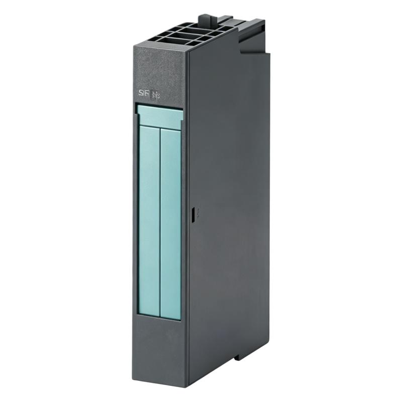
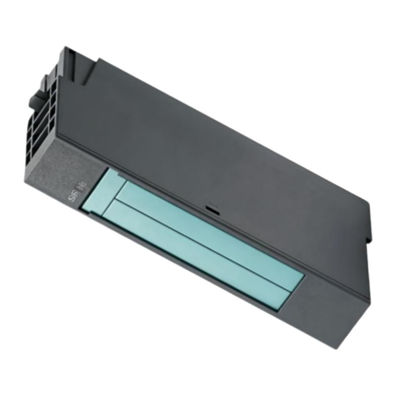
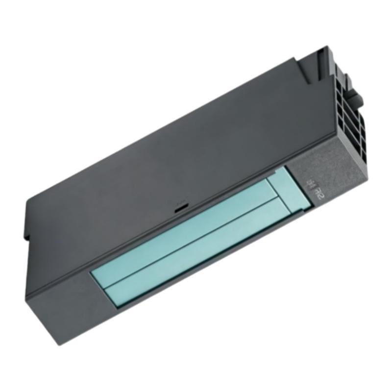
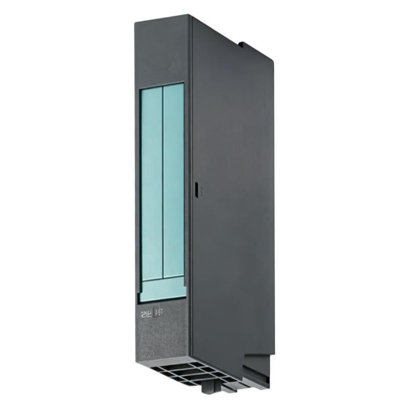
- Siemens
- 6AG1134-4LB02-2AB0
- Analog Input Module
- Germany
- 15 × 81 × 52 mm
- 0.045 kg
- Xiamen, China
- New & In Stock
- T/T, PayPal, Western Union
- 1 Year
- 1-3 Working Days
- DHL, UPS, TNT, FedEx and EMS.
- 24-Hour Service
- COO
- 71
Our advantage

Global Logistics
We have a 10-year logistics and express cooperation agreement, so our products can be shipped to any place in the world.

Brand new and original
Our products are imported in bulk from the place of origin. Because of the cooperative relationship, our products are all original and 100% new.

24-hour service
We provide 7*24 hours service to our customers. We will be there whenever you need us.

Price advantage
All our products are priced very favorably because we have our own warehouse and supply.
| Company Information | |||
| [email protected] | |||
| Mobile | +8615980777398 | ||
| +8615980777398 | |||
| 15980777398 |
Product Overview
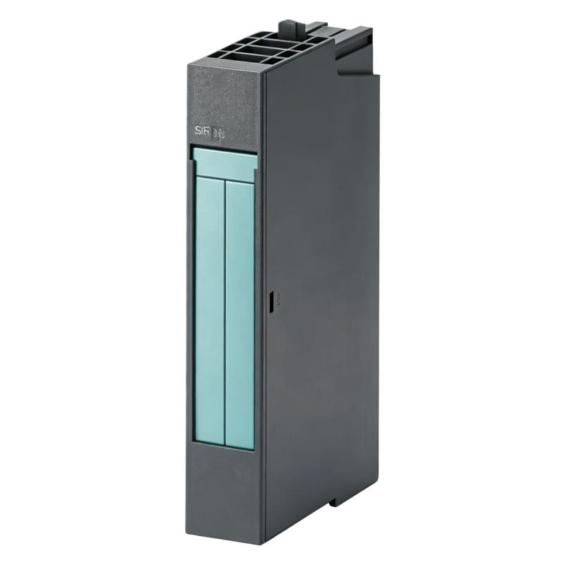
The Siemens 6AG1134-4LB02-2AB0 is a SIPLUS ET 200S EM 2AI HF analog input module designed for use in Siemens SIMATIC ET 200S distributed I/O systems. It is based on the 6ES7134-4LB02-0AB0 module and features conformal coating for improved resistance to demanding industrial environmental conditions. The module provides two analog voltage inputs and is designed for high-feature applications requiring fast signal acquisition and diagnostic capability.
The module supports voltage input ranges including ±10 V, ±5 V, and 1–5 V, with resolutions of up to 15-bit plus sign depending on the selected range. Its specified cycle time can be as low as 0.5 ms for the module, making it suitable for applications where analog values need to be acquired rapidly.
The 6AG1134-4LB02-2AB0 has a compact 15 × 81 × 52 mm form factor and a specified weight of approximately 0.045 kg. Siemens documentation identifies it as a SIPLUS ET 200S module with conformal coating, while the corresponding product data identifies the module as an electronic module with a 15 mm overall width.
This article provides a practical installation, commissioning, fault-diagnosis, and maintenance guide for the module.
Product Identification
| Parameter | Specification |
|---|---|
| Manufacturer | Siemens |
| Product Family | SIPLUS ET 200S |
| Model | 6AG1134-4LB02-2AB0 |
| Product Type | Analog Input Module |
| Module Description | SIPLUS ET 200S EM 2AI HF |
| Number of Analog Inputs | 2 |
| Input Type | Voltage |
| Input Ranges | ±10 V, ±5 V, 1–5 V |
| Resolution | Up to 15-bit + sign |
| Module Cycle Time | Up to 0.5 ms |
| Rated Load Voltage | 24 V DC |
| Reverse Polarity Protection | Yes |
| Typical Power Loss | 0.85 W |
| Dimensions | 15 × 81 × 52 mm |
| Weight | 0.045 kg |
| Base Module | 6ES7134-4LB02-0AB0 |
| Application | SIMATIC ET 200S Distributed I/O |
| Environmental Design | Conformal Coating |
The technical data above reflects available product documentation; exact operating limits should always be matched to the selected input mode and complete ET 200S system configuration.
What Is the Siemens 6AG1134-4LB02-2AB0?
The 6AG1134-4LB02-2AB0 is a high-feature analog input module within the SIPLUS ET 200S family.
Its primary purpose is to acquire voltage-based analog signals from industrial sensors, transmitters, and measuring devices and transfer the resulting measurement data into the ET 200S automation system.
The module provides two analog inputs. Its supported voltage ranges include:
- ±10 V
- ±5 V
- 1–5 V
The module provides high-resolution signal acquisition, with the product data specifying 15-bit plus sign for the bipolar voltage ranges and 15-bit for the 1–5 V range.
A typical application can be represented as:
Industrial Sensor
↓
Analog Voltage Signal
↓
6AG1134-4LB02-2AB0
↓
ET 200S Interface / Backplane
↓
PLC CPU
↓
Control Program
↓
HMI / SCADA / Process Control
This makes the module an important interface between field-level measurement equipment and the PLC control layer.
Main Technical Characteristics
Two Analog Voltage Inputs
The module provides two analog input channels, allowing two independent voltage-based measurement signals to be acquired by the ET 200S system.
This can be useful for applications such as:
- Pressure monitoring
- Temperature transmitter interfaces
- Position measurement
- Speed feedback
- Process-variable monitoring
- Machine instrumentation
The actual sensor type must be compatible with the configured voltage input range.
Supported Input Ranges
The documented voltage input ranges include:
| Input Range | Resolution |
|---|---|
| ±10 V | 15-bit + sign |
| ±5 V | 15-bit + sign |
| 1–5 V | 15-bit |
Correct configuration is important because a mismatch between the field transmitter and module configuration can result in incorrect measurements or diagnostic conditions.
High-Speed Analog Acquisition
The module specifies a cycle time of up to 0.5 ms under the applicable operating conditions. The product documentation also distinguishes operating behavior depending on whether interference suppression is used.
This characteristic makes the module appropriate for applications where analog values must be acquired relatively quickly.
24 V DC System Supply
The module is associated with a 24 V DC load voltage system. Product documentation specifies a rated value of 24 V DC and reverse-polarity protection.
Before commissioning, verify the actual supply conditions at the ET 200S station and ensure that the complete system is wired according to the approved electrical design.
Compact Physical Design
The specified module dimensions are:
15 × 81 × 52 mm
The 15 mm width is particularly useful in distributed I/O installations where cabinet space is limited. Siemens documentation also lists an approximate weight of 45 g.
Conformal-Coated SIPLUS Construction
One important distinction of the 6AG1134-4LB02-2AB0 is its SIPLUS design with conformal coating.
The product is described as being based on the standard 6ES7134-4LB02-0AB0 and supplied with conformal coating. The product documentation identifies enhanced environmental resistance for demanding industrial conditions.
This makes environmental assessment an important part of installation planning.
Installation Guide
1. Verify the Model
Before installation, confirm the exact ordering number:
6AG1134-4LB02-2AB0
Do not confuse it with the standard 6ES7 version or other SIPLUS analog input modules.
The complete order number should be checked against the system configuration.
2. Confirm the ET 200S Architecture
Before installing the module, verify:
- ET 200S station configuration
- Interface module
- Terminal module
- Module position
- PLC configuration
- Power arrangement
- Field wiring
The module is designed as part of the ET 200S distributed I/O architecture rather than as a standalone PLC analog card.
3. Inspect the Module
Check the module for:
- Damaged housing
- Bent contacts
- Cracks
- Contamination
- Corrosion
- Mechanical deformation
- Signs of overheating
The conformal coating provides environmental protection, but it should not be treated as protection against incorrect electrical installation.
4. Check Physical Dimensions
The module occupies approximately:
15 mm width × 81 mm height × 52 mm depth
Ensure adequate clearance for:
- Installation
- Terminal connections
- Wiring
- Inspection
- Maintenance
5. Verify the Field Signal
Before wiring, determine what the connected instrument provides.
Verify whether the field device outputs:
- ±10 V
- ±5 V
- 1–5 V
Do not connect a current-output transmitter to a voltage input simply because the transmitter is an analog device.
6. Isolate Power
Before installing or removing the module:
- Stop the controlled process.
- Place the equipment into a safe state.
- Shut down the affected ET 200S station as required.
- Isolate applicable electrical power.
- Apply lockout/tagout procedures where required.
- Verify that hazardous voltage has been removed.
7. Install the Module
Insert the module into the designated ET 200S position.
Verify:
- Correct orientation
- Correct module position
- Proper mechanical engagement
- Secure seating
- No interference with adjacent components
Do not force the module into position.
8. Connect the Terminal System
The analog module operates as part of the ET 200S terminal-module architecture.
Verify the associated terminal module and ensure that the field wiring matches the engineering drawings.
9. Connect Analog Signals
Connect the two analog channels according to the approved wiring diagram.
Pay attention to:
- Channel number
- Signal polarity
- Signal reference
- Shielding
- Cable routing
- Grounding
A reversed or incorrectly referenced voltage signal can cause an incorrect process value even when the analog module itself is functioning normally.
10. Separate Analog and Power Cables
Where practical, route analog cables separately from:
- Motor power cables
- VFD cables
- Contactor circuits
- High-current conductors
- Switching circuits
This reduces the possibility of electromagnetic interference.
11. Verify Shielding
Use the approved plant grounding and shielding strategy.
Improper shielding can create:
- Ground loops
- Noise
- Offset
- Signal instability
Do not change the grounding arrangement without considering the complete control-system design.
Configuration Procedure
Step 1 – Add the Module to the Hardware Configuration
Configure the 6AG1134-4LB02-2AB0 in the appropriate ET 200S station.
Verify the module position and hardware identification.
Step 2 – Configure the Input Channels
Configure each analog input according to the connected transmitter.
For example:
Channel 1 → ±10 V
Channel 2 → 1–5 V
The actual configuration must match the field instrumentation.
Step 3 – Configure Signal Processing
Configure the applicable analog processing parameters according to the application requirements.
Where interference suppression is necessary, ensure that the selected configuration is consistent with the required response time.
Step 4 – Download the Hardware Configuration
Transfer the configuration to the controller or distributed I/O system according to the approved commissioning procedure.
Step 5 – Check Module Diagnostics
After startup, check the module and ET 200S station for:
- Module recognition
- Group fault indications
- Channel diagnostics
- Communication status
- Power status
The product description specifies an SF LED for group fault indication.
Step 6 – Check Raw Analog Values
Monitor the raw input data.
Apply a known test signal where practical and compare the PLC value against the expected measurement.
Step 7 – Configure Engineering Scaling
Convert the raw analog value into engineering units such as:
- °C
- bar
- %
- mm
- m/s
- rpm
The scaling must correspond to the transmitter’s actual operating range.
Step 8 – Verify HMI / SCADA
Check that the engineering value shown by the HMI or SCADA system matches the expected process measurement.
Troubleshooting Guide
Fault 1 – Module Is Not Recognized
Possible Causes
- Incorrect hardware configuration
- Module not seated correctly
- ET 200S interface problem
- Terminal-module problem
- Power interruption
- Incorrect module identification
Diagnostic Procedure
Check:
Hardware Configuration → Interface Module → Terminal Module → IC695?
For this Siemens module, the actual signal path should instead be checked as:
Hardware Configuration → ET 200S Interface → Terminal Module → 6AG1134-4LB02-2AB0
Verify the physical module position against the engineering configuration.
Fault 2 – Analog Channel Reads Zero
Possible causes include:
- Open signal circuit
- Incorrect wiring
- Incorrect voltage range
- Failed transmitter
- Incorrect channel configuration
- Missing field-device power
- Terminal connection problem
Start with the field instrument and measure the actual voltage at the module input.
Fault 3 – Analog Reading Is Too High
Possible causes include:
- Incorrect input range
- Excessive field signal
- Incorrect scaling
- Wiring problem
- Grounding issue
- Incorrect transmitter configuration
First compare the actual field voltage with the expected transmitter output.
Fault 4 – Analog Reading Is Too Low
Possible causes include:
- Weak transmitter output
- Incorrect range
- Poor connection
- Cable resistance
- Incorrect scaling
- Signal-reference problem
Measure the field signal independently.
Fault 5 – Analog Signal Fluctuates
Possible causes include:
- Electromagnetic interference
- Poor shielding
- Ground loop
- Loose terminal
- Unstable transmitter
- Damaged cable
- Nearby motor or VFD
If the physical process is stable but the PLC value fluctuates significantly, investigate signal integrity first.
Fault 6 – Both Channels Are Incorrect
If both channels show similar errors, investigate common causes:
- Hardware configuration
- Module supply
- Terminal module
- Grounding
- Shielding
- Common reference
- System configuration
A common problem is more likely than two independent sensor failures.
Fault 7 – Only One Channel Is Incorrect
If only one channel is faulty, check:
- Sensor
- Transmitter
- Channel wiring
- Terminal
- Input configuration
- Channel-specific conditions
Swap test signals only when the system design and safety procedure permit it.
Fault 8 – SF Fault Indication Appears
An SF or group-fault indication can indicate a diagnostic condition associated with the module or station.
Check:
- Hardware configuration
- Input signal
- Wiring
- Module status
- ET 200S station diagnostics
- Power conditions
Do not clear the fault without identifying the underlying cause.
Fault 9 – Reading Is Correct at the Module but Wrong on HMI
If the raw PLC value is correct but the HMI value is incorrect, investigate:
- PLC scaling
- Engineering-unit conversion
- HMI tag
- Decimal position
- HMI data type
- PLC application logic
The hardware may be operating normally.
Fault 10 – Measurement Drifts Over Time
Potential causes include:
- Sensor drift
- Transmitter drift
- Temperature effects
- Cable problems
- Calibration issues
- Environmental conditions
Compare the measurement with an independent calibrated reference.
Fault 11 – Fast Process Changes Are Not Reflected Correctly
If the physical signal changes rapidly but the PLC value appears delayed, check:
- Configuration
- Signal filtering
- Interference suppression
- PLC scan behavior
- Application processing
The specified module cycle time can be affected by operating configuration, so the selected signal-processing settings should be considered when fast acquisition is required.
Diagnostic Flow
A practical troubleshooting sequence is:
Sensor
↓
Transmitter
↓
Analog Voltage
↓
Field Wiring
↓
Terminal Module
↓
6AG1134-4LB02-2AB0
↓
ET 200S Interface
↓
PLC
↓
Scaling
↓
HMI / SCADA
This method helps separate field instrumentation faults from distributed-I/O hardware and PLC application problems.
Preventive Maintenance
Module Inspection
Inspect periodically for:
- Mechanical damage
- Contamination
- Corrosion
- Abnormal discoloration
- Connector problems
Terminal Inspection
Check:
- Terminal security
- Cable condition
- Signal polarity
- Shield connections
- Mechanical strain
Signal Cable Inspection
Inspect analog cables for:
- Cuts
- Abrasion
- Crushing
- Improper routing
- Damaged shielding
- Excessive bending
Environmental Inspection
The SIPLUS design is intended for demanding industrial environments, but the complete installation should still be reviewed for:
- Temperature
- Condensation
- Chemical exposure
- Dust
- Salt exposure
- Oil
- Mechanical stress
Environmental protection at the module does not eliminate the need for proper cabinet and wiring design.
Power Inspection
Verify that the station power remains within the applicable operating range.
The product documentation identifies 24 V DC as the rated load-voltage value.
Configuration Backup
Maintain backups of:
- PLC program
- Hardware configuration
- ET 200S configuration
- Analog input parameters
- Scaling
- Alarm settings
This can significantly reduce recovery time after hardware replacement.
Preventive Maintenance Table
| Maintenance Area | Recommended Action |
|---|---|
| Module | Inspect housing and contacts |
| Terminal Module | Check connections |
| Analog Cables | Inspect for damage |
| Shielding | Verify grounding strategy |
| Power | Check station supply |
| Configuration | Verify module parameters |
| Scaling | Verify engineering conversion |
| Diagnostics | Review recurring faults |
| Environment | Monitor operating conditions |
| Backup | Maintain current configuration |
Industrial Applications
Process Monitoring
The module can be used for continuous acquisition of process variables represented by voltage signals.
Typical applications include:
- Pressure
- Temperature
- Flow
- Level
- Position
Machine Control
Voltage-based sensors can provide feedback for:
- Position control
- Speed monitoring
- Machine condition monitoring
- Process sequencing
Packaging Equipment
Fast analog acquisition can be useful in machine applications where measurement information must be processed quickly.
Production Lines
Distributed ET 200S I/O installations can place analog measurement modules close to the field equipment, reducing unnecessary signal wiring distances.
Process Instrumentation
The module can be used where compatible voltage-output transmitters provide continuous process information to the PLC.
Equipment Monitoring
Analog measurements can support:
- Alarm generation
- Equipment protection
- Predictive maintenance data
- Process optimization
Replacement Procedure
1. Identify the Existing Module
Confirm:
Siemens 6AG1134-4LB02-2AB0
Record:
- Station location
- Module position
- Channel assignments
- Signal ranges
- Connected field devices
2. Back Up Configuration
Save the current:
- PLC program
- Hardware configuration
- ET 200S configuration
- Analog settings
- Scaling
- Alarm parameters
3. Document Field Wiring
Record:
- Channel 1 wiring
- Channel 2 wiring
- Signal polarity
- Common connections
- Shielding
4. Put the Process in a Safe State
Determine the consequences of losing the two analog input channels before removing the module.
5. Isolate Power
Disconnect the applicable supply and verify safe conditions.
6. Remove the Existing Module
Remove the module according to the approved ET 200S maintenance procedure.
Avoid damaging the terminal module or field wiring.
7. Inspect the Interface
Check:
- Module contacts
- Terminal module
- Wiring
- Shielding
- Adjacent components
8. Install the Replacement
Install the replacement 6AG1134-4LB02-2AB0 in the correct ET 200S position.
9. Reconnect the Field Signals
Reconnect both analog channels according to the documented wiring arrangement.
Verify polarity and channel assignment.
10. Restore Hardware Configuration
Confirm that the PLC configuration identifies the correct module in the correct position.
11. Restore Power
Restart the ET 200S station according to the approved procedure.
12. Check Diagnostics
Verify:
- Module recognition
- SF status
- Station communication
- Channel status
- Power status
13. Verify Analog Measurements
Apply known process conditions or test signals.
Compare the raw PLC value against the expected input.
14. Verify Scaling and HMI
Confirm:
- Engineering units
- Scaling
- Alarms
- HMI display
- Process response
Technical Specifications Summary
| Parameter | Value |
|---|---|
| Manufacturer | Siemens |
| Model | 6AG1134-4LB02-2AB0 |
| Family | SIPLUS ET 200S |
| Module Type | EM 2AI HF Analog Input |
| Number of Inputs | 2 |
| Signal Type | Voltage |
| Input Ranges | ±10 V, ±5 V, 1–5 V |
| Resolution | 15-bit + sign / 15-bit |
| Cycle Time | Up to 0.5 ms |
| Rated Load Voltage | 24 V DC |
| Reverse Polarity Protection | Yes |
| Typical Power Loss | 0.85 W |
| Width | 15 mm |
| Height | 81 mm |
| Depth | 52 mm |
| Weight | Approx. 0.045 kg |
| Base Module | 6ES7134-4LB02-0AB0 |
| Product Design | SIPLUS with conformal coating |
The dimensions and approximately 45 g weight are consistent with the available Siemens product documentation.
Key Advantages
- Siemens SIPLUS ET 200S analog input design
- Two analog voltage input channels
- Supports ±10 V, ±5 V, and 1–5 V signal ranges
- Up to 15-bit plus sign resolution for bipolar ranges
- Fast module cycle time
- Compact 15 mm-wide design
- Conformal-coated construction for demanding industrial environments
- Reverse-polarity protection
- Suitable for distributed industrial I/O applications
- Suitable for process measurement and machine-control applications
Technical FAQs
What is the Siemens 6AG1134-4LB02-2AB0?
It is a SIPLUS ET 200S EM 2AI HF analog input module designed to acquire voltage-based analog signals in compatible ET 200S distributed I/O systems.
How many analog inputs does it have?
The module provides 2 analog inputs.
What signal ranges does it support?
The documented voltage ranges include ±10 V, ±5 V, and 1–5 V.
What is the resolution?
The documented resolution is 15-bit plus sign for ±10 V and ±5 V ranges, and 15-bit for the 1–5 V range.
What are its dimensions?
The specified dimensions are 15 × 81 × 52 mm.
How much does the module weigh?
The specified weight is approximately 0.045 kg, or 45 g.
What is the difference between this module and the standard 6ES7134-4LB02-0AB0?
The 6AG1134-4LB02-2AB0 is the SIPLUS version based on the standard module and incorporates conformal coating for enhanced environmental resistance.
Can the module be used with a current-output transmitter?
The documented input ranges for this specific module are voltage ranges. A current-output transmitter should therefore not be connected without an appropriate signal-conditioning solution designed for the application.
Why does the analog value fluctuate?
Possible causes include electrical interference, poor shielding, grounding problems, loose connections, unstable transmitters, and damaged cables.
What should be checked if the module generates a group fault?
Check the hardware configuration, module seating, terminal connections, input signal, station power, and available diagnostic information.
Why is scaling important?
The analog module provides measurement data, while the PLC application normally converts the raw value into meaningful engineering units. Incorrect scaling can therefore produce an incorrect displayed process value even when the electrical input is correct.
Is the module suitable for demanding industrial environments?
The SIPLUS version uses conformal-coated construction and is designed for more demanding environmental conditions than a conventional module, but the complete installation must still meet the applicable environmental and electrical requirements.
Conclusion
The Siemens 6AG1134-4LB02-2AB0 SIPLUS ET 200S Analog Input Module is a compact two-channel voltage-input module designed for compatible ET 200S distributed I/O systems. Its documented 15 × 81 × 52 mm dimensions and approximately 0.045 kg weight make it suitable for space-constrained control cabinets, while its SIPLUS conformal-coated construction provides additional environmental protection.
The module supports ±10 V, ±5 V, and 1–5 V analog voltage signals and provides high-resolution acquisition with a specified cycle time of up to 0.5 ms under applicable conditions.
For installation, the most important considerations are correct ET 200S system compatibility, proper terminal-module integration, accurate channel configuration, correct signal polarity, appropriate shielding, and separation of analog wiring from high-power electrical circuits.
For troubleshooting, technicians should follow the complete signal path from the sensor and transmitter through the field wiring and terminal module to the 6AG1134-4LB02-2AB0, ET 200S interface, PLC data, and scaling logic. This structured approach helps distinguish a genuine analog input hardware problem from transmitter, wiring, configuration, grounding, or application-level faults.
With appropriate installation, configuration, and preventive maintenance, the module can provide reliable analog signal acquisition for industrial process monitoring, machine automation, equipment monitoring, and distributed control applications.