

ProductPRODUCT
Featured products
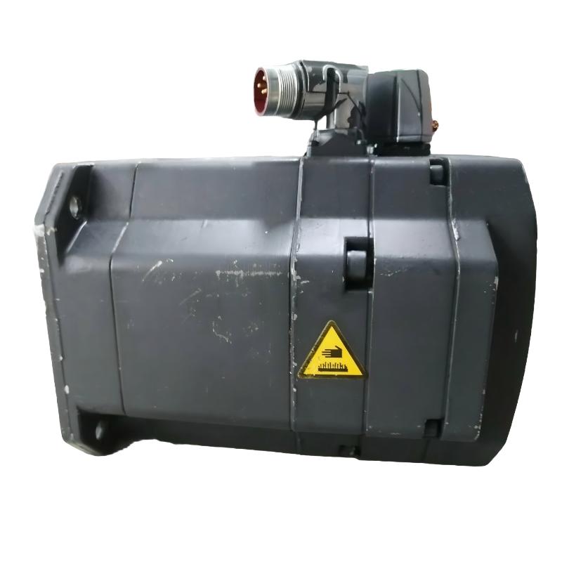
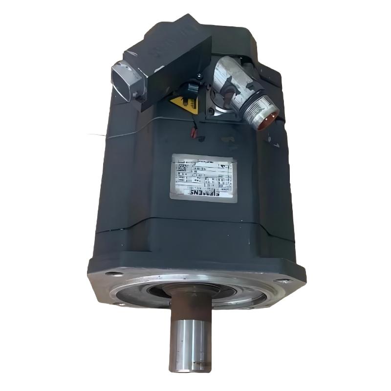
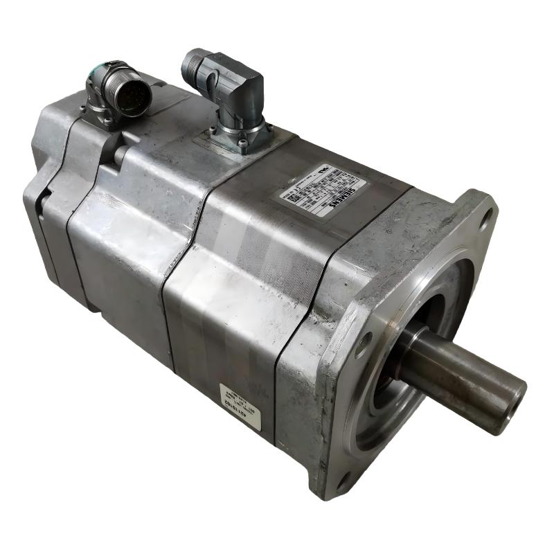
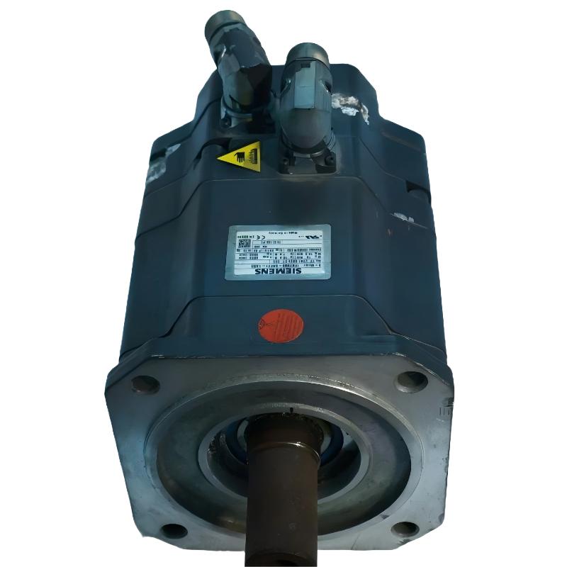
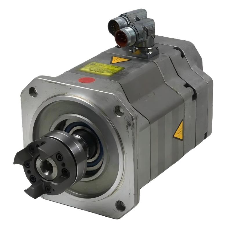
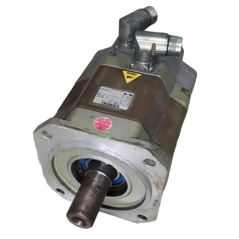
Contact Us
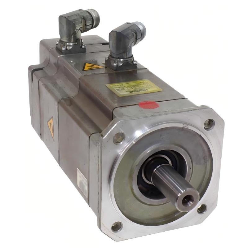
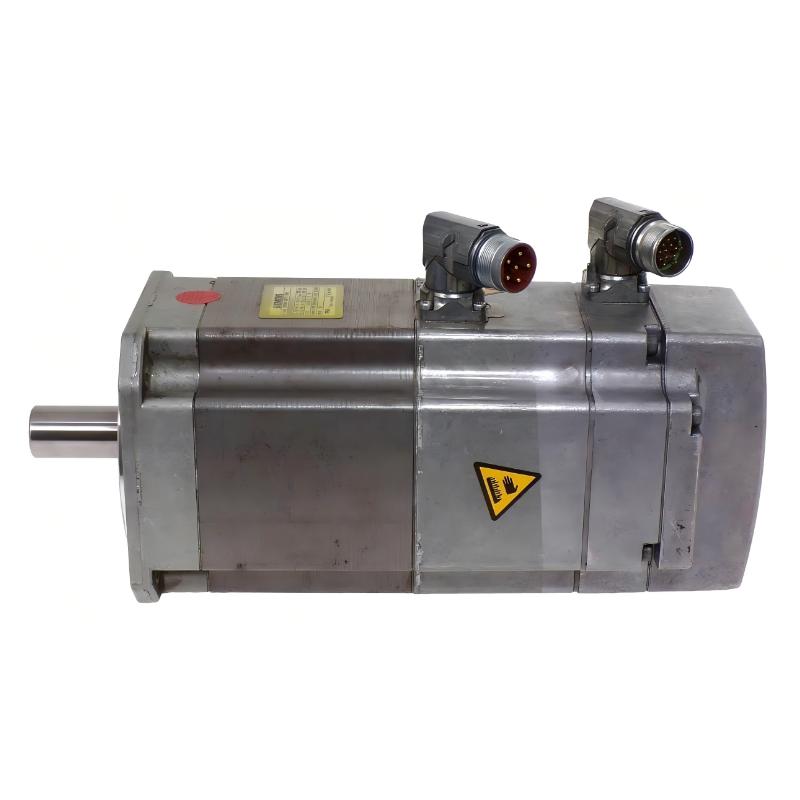
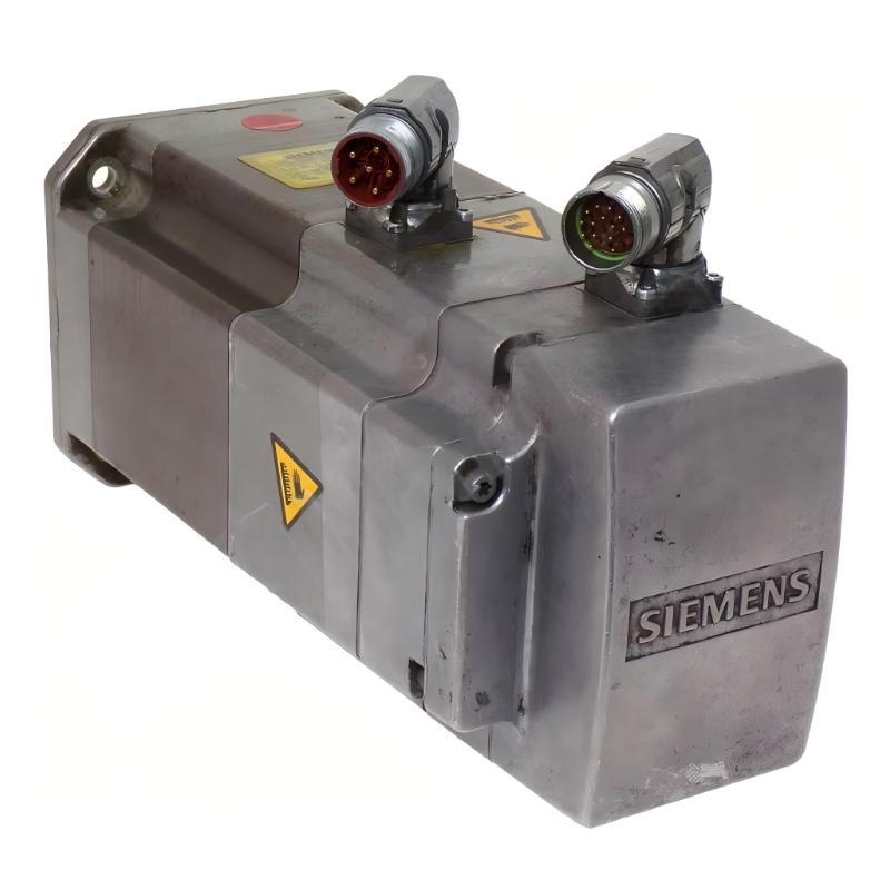
- Siemens
- 1FK7063-5AF71-1EH0
- Permanent-magnet Synchronous Compact Servo Motor
- Germany
- 63 mm shaft height
- 12kg
- Xiamen, China
- New & In Stock
- T/T, PayPal, Western Union
- 1 Year
- 1-3 Working Days
- DHL, UPS, TNT, FedEx and EMS.
- 24-Hour Service
- COO
- 4
Our advantage

Global Logistics
We have a 10-year logistics and express cooperation agreement, so our products can be shipped to any place in the world.

Brand new and original
Our products are imported in bulk from the place of origin. Because of the cooperative relationship, our products are all original and 100% new.

24-hour service
We provide 7*24 hours service to our customers. We will be there whenever you need us.

Price advantage
All our products are priced very favorably because we have our own warehouse and supply.
| Company Information | |||
| [email protected] | |||
| Mobile | +8615980777398 | ||
| +8615980777398 | |||
| 15980777398 |
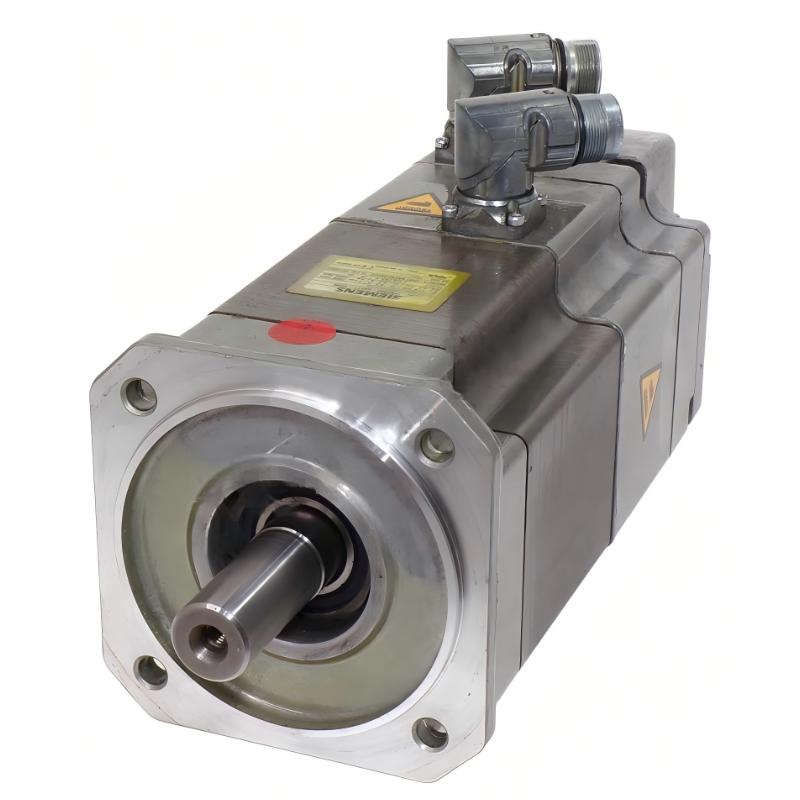
Siemens 1FK7063-5AF71-1EH0 Servo Motor: Product Specifications, Features, Applications, Advantages, and Related Models
1. Product Overview
The Siemens 1FK7063-5AF71-1EH0 is a permanent-magnet synchronous servo motor belonging to the SIMOTICS S-1FK7 family. This motor series is designed for industrial motion control applications that require accurate positioning, controlled acceleration, stable rotational speed, and reliable dynamic performance.
The 1FK7 family is commonly associated with automated production equipment, CNC machinery, packaging systems, material handling equipment, and other industrial applications where precise control of mechanical movement is essential.
Servo motors differ from conventional induction motors because they are generally used as part of a closed-loop motion control system. A servo drive regulates the motor’s current, speed, and position according to commands from a controller. Depending on the motor configuration, feedback devices provide information that allows the control system to correct positioning or speed errors during operation.
The 1FK7063-5AF71-1EH0 is therefore best evaluated as a component of an integrated motion control system rather than as an isolated electric motor. Its suitability depends on the required torque, speed, acceleration, duty cycle, mounting arrangement, feedback configuration, and compatibility with the selected servo drive.
Important specification note: The following overview distinguishes established characteristics of the 1FK7 product family from information that requires confirmation against the exact motor configuration. The complete ordering code identifies a specific variant, and its electrical and mechanical characteristics should not be assumed to be identical to those of other 1FK7 motors. Exact numerical ratings, dimensions, and weight are not supplied here as verified facts because the complete technical record for this particular ordering code is not available in the information provided.
2. Brand, Product Series, and Product Classification
| Item | Detailed information |
|---|---|
| Brand | Siemens |
| Product family | SIMOTICS |
| Product series | SIMOTICS S-1FK7 |
| Product type | AC synchronous servo motor |
| Motor technology | Permanent-magnet synchronous motor |
| Model number | 1FK7063-5AF71-1EH0 |
| Frame size | 63 mm shaft height |
| Rated speed | 3,000 rpm |
| Rated torque | 7.3 Nm at the specified 100 K temperature rise |
| Static torque | 11.0 Nm at the specified 100 K temperature rise |
| Optimum operating power | Approximately 2.3 kW |
| Rated current | 5.6 A |
| Cooling method | Natural cooling |
| Mounting arrangement | IM B5; also supports the specified IM V1 and IM V3 arrangements |
| Encoder | Absolute encoder, 2048 increments per revolution, multi-turn capability, EnDat interface |
| Holding brake | Integrated permanent-magnet holding brake |
| Shaft configuration | Plain shaft |
| Protection rating | IP64 |
| Motor weight | 12.0 kg net motor weight, according to the technical data for this configuration |
| Typical application | Industrial automation and precision motion control |
The SIMOTICS S-1FK7 series is intended for servo applications in which compact construction, dynamic response, precise motion control, and integration with industrial drive systems are important.
The 1FK7063-5AF71-1EH0 is a specific configuration within this series. Its encoder, holding brake, shaft arrangement, mounting configuration, and protection rating are important selection criteria because two motors with similar base model numbers may not have identical mechanical or electrical interfaces.
2.1 Product Positioning
This model occupies a role in the industrial servo motor category where controlled movement and repeatable positioning matter more than simply running continuously at a fixed speed.
A conventional motor may be suitable for a fan, pump, or other application with relatively simple speed requirements. A servo motor is more appropriate when a machine must accelerate quickly, stop at a defined position, synchronize with another axis, or maintain a controlled motion profile.
The 1FK7 family can be used in applications involving rotary motion, linear axes driven through mechanical transmission systems, and automated equipment that requires coordinated movement.
The actual performance of a complete system depends on the motor, servo drive, feedback device, controller, mechanical transmission, and machine load working together.
2.2 Product Identification
The complete ordering code 1FK7063-5AF71-1EH0 should be used when identifying the product for purchasing, maintenance, or replacement.
The base model number alone is not always sufficient. Different suffixes may indicate differences in encoder technology, brake availability, shaft design, connector arrangement, or protection characteristics.
Before ordering a replacement, compare the complete nameplate information and confirm the drive interface, feedback compatibility, mounting dimensions, shaft arrangement, and brake requirements.
This is especially important for older industrial installations, where the motor may be integrated into a machine designed around a particular generation of servo drive technology.
3. Detailed Technical Specifications
The following table summarizes the principal electrical, mechanical, and performance characteristics of the 1FK7063-5AF71-1EH0.
| Parameter | Specification | Technical explanation |
|---|---|---|
| Model | 1FK7063-5AF71-1EH0 | Complete motor ordering code |
| Brand | Siemens | Industrial automation and motion control equipment |
| Product series | SIMOTICS S-1FK7 | Synchronous servo motor family |
| Motor type | Permanent-magnet synchronous motor | Uses permanent magnets in the rotor |
| Rated speed | 3,000 rpm | Rated operating speed under the specified conditions |
| Rated torque | 7.3 Nm | Continuous rated torque at the specified 100 K temperature rise |
| Static torque | 11.0 Nm | Static torque rating at the specified 100 K temperature rise |
| Static torque, alternative thermal condition | 9.1 Nm | Static torque at the specified 60 K temperature rise |
| Optimum operating power | Approximately 2.3 kW | Power associated with the specified optimum operating point |
| Rated current | 5.6 A | Rated current under the stated thermal conditions |
| Stall current | 8.0 A | Stall current at the specified 100 K temperature rise |
| Stall current, alternative thermal condition | 6.6 A | Stall current at the specified 60 K temperature rise |
| Maximum permissible mechanical speed | 7,200 rpm | Mechanical speed limit stated for the configuration |
| Maximum speed with inverter | 6,600 rpm | Inverter-related speed limit stated for the configuration |
| Maximum motor torque | 35.0 Nm | Motor limiting value; not the same as continuous rated torque |
| Maximum current | 28.0 A | Motor limiting current; the drive and operating conditions must be considered |
| Number of poles | 8 | Rotor and stator electromagnetic configuration |
| Torque constant | 1.37 Nm/A | Torque generated per ampere under the specified conditions |
| Voltage constant at 20°C | 87.5 V/1,000 rpm | Voltage constant stated in the motor technical data |
| Winding resistance at 20°C | 0.65 Ω | Electrical resistance of the winding under the stated conditions |
| Rotating-field inductance | 7.7 mH | Electrical characteristic relevant to drive control |
| Electrical time constant | 11.80 ms | Characteristic associated with the electrical response |
| Mechanical time constant | 1.56 ms | Characteristic associated with the mechanical response |
| Thermal time constant | 40 minutes | Approximate characteristic of the motor’s thermal response |
| Rotor moment of inertia | 17.300 kg·cm² | Relevant to acceleration and deceleration calculations |
| Efficiency | 91.0% | Stated efficiency value; actual system efficiency depends on operating conditions |
| Cooling | Natural cooling | Does not require a separate forced-air cooling system for the specified configuration |
| Mounting type | IM B5 | Flange mounting arrangement |
| Alternative mounting positions | IM V1 and IM V3 | Specified vertical mounting arrangements |
| Shaft height | 63 mm | Nominal frame shaft height |
| Shaft type | Plain shaft | Shaft configuration without an integrated fitted key |
| Encoder type | Absolute encoder | Provides absolute position information |
| Encoder resolution | 2048 increments per revolution | Encoder specification for the identified configuration |
| Multi-turn capability | 4,096 revolutions | Multi-turn position capability stated for the encoder |
| Encoder interface | EnDat | Digital feedback interface |
| Holding brake | Yes | Integrated permanent-magnet holding brake |
| Holding brake torque | 13.0 Nm | Specified holding torque |
| Brake supply | 24 V DC ±10% | Required brake supply voltage |
| Brake coil current | 0.8 A | Specified brake coil current |
| Brake opening time | 100 ms | Stated opening time |
| Brake closing time | 50 ms | Stated closing time |
| Maximum braking work | 380 J | Specified braking-work limit |
| Protection rating | IP64 | Protection against dust ingress and water splashing |
| Temperature monitoring | KTY84 temperature sensor | Temperature monitoring within the stator winding |
| Connector arrangement | Power and signal connectors | Connectors can be rotated through the specified range |
| Connector rotation | Up to 270° | Facilitates cable routing within the permitted installation arrangement |
| Radial runout tolerance | 0.040 mm | Mechanical accuracy characteristic |
| Concentricity tolerance | 0.10 mm | Mechanical alignment characteristic |
| Axial runout tolerance | 0.10 mm | Mechanical accuracy characteristic |
| Vibration severity | Grade A | Stated vibration classification |
| Motor dimensions (mm) | Exact overall dimensions require confirmation | Frame height alone does not establish the motor’s full length, width, or depth |
| Net motor weight (kg) | 12.0 kg | Stated net motor weight; shipping weight may differ |
3.1 Understanding Rated Torque and Static Torque
Rated torque and static torque describe different operating conditions.
The rated torque of 7.3 Nm represents the specified continuous operating capability under the stated thermal conditions. It is an important value when estimating whether the motor can sustain the load during normal production.
The static torque rating of 11.0 Nm describes a different thermal operating condition. It should not automatically be interpreted as the torque available continuously under every speed, ambient temperature, and installation condition.
When selecting a servo motor, engineers should calculate the torque required throughout the entire motion cycle. This includes acceleration, deceleration, steady-speed operation, stopping, and any periods when the motor must resist an external force.
A motor that can produce sufficient peak torque for a short acceleration period may still be unsuitable if the continuous RMS torque exceeds its thermal capability.
3.2 Understanding Maximum Speed
The specified mechanical speed limit is 7,200 rpm, while the stated inverter-related speed limit is 6,600 rpm.
These values are limits rather than recommended continuous operating speeds. The permissible operating speed depends on the selected drive, DC bus voltage, motor voltage requirements, load characteristics, mechanical balance, bearing conditions, and the application’s operating profile.
For a machine designed to operate around 3,000 rpm, the rated speed is the more useful initial reference. Higher-speed operation requires an assessment of torque availability, power demand, and mechanical constraints.
3.3 Understanding the Holding Brake
The integrated holding brake is intended to hold a stationary axis in position when the brake is engaged.
It is particularly useful for vertical axes, lifting mechanisms, and machine components that could move under gravity or an external load when the motor is not actively producing torque.
A holding brake should not automatically be treated as a dynamic stopping brake. Emergency stopping and repeated dynamic braking require a separate assessment of brake suitability, stopping energy, cycle frequency, and machine safety requirements.
For a vertical axis, the brake should be incorporated into a properly designed safety and control system rather than relied upon as the only protective measure.
3.4 Dimensions and Installation Space
The motor has a nominal shaft height of 63 mm, which provides an important reference for mechanical integration.
However, shaft height is not the same as the motor’s overall length or external dimensions. A complete installation drawing is required to establish the flange dimensions, shaft extension, connector clearance, mounting-hole arrangement, and the space needed for cables.
The overall dimensions should therefore be verified before designing a mounting plate, replacing an existing motor, or determining whether the motor fits inside a machine enclosure.
The listed net motor weight is 12.0 kg. For equipment design, the weight of the motor alone must be distinguished from the combined weight of the motor, cables, mounting hardware, coupling, and any attached transmission components.
4. Product Introduction
The Siemens 1FK7063-5AF71-1EH0 is a compact industrial servo motor developed for applications requiring controlled rotary movement, repeatable positioning, and reliable integration with an automated motion control system.
Its permanent-magnet synchronous design provides a combination of torque density, dynamic response, and controlled operation. The motor can be incorporated into machinery where movement must follow a programmed position, speed, or acceleration profile rather than simply operate at a constant speed.
The motor’s 3,000 rpm rated speed and 7.3 Nm rated torque make it relevant to medium-duty industrial motion applications, subject to the actual load requirements and operating cycle.
The integrated absolute encoder provides position feedback, while the holding brake can help maintain the position of a stationary axis when correctly controlled. Natural cooling simplifies the cooling arrangement compared with designs that require a dedicated external cooling circuit or forced-air system.
4.1 Permanent-Magnet Synchronous Technology
The motor uses permanent magnets in its rotor and a controlled rotating magnetic field in its stator.
The servo drive supplies controlled electrical current to produce the required torque. By adjusting the electrical output according to the motion command and feedback information, the system can regulate acceleration, speed, and position.
This technology is particularly useful in machines that repeatedly move between defined positions or need coordinated movement across multiple axes.
Typical examples include a packaging machine that indexes products into position, a CNC machine that moves a cutting tool along a programmed path, or a pick-and-place system that transfers components between workstations.
4.2 Compact Mechanical Design
The motor’s 63 mm shaft height provides a relatively compact mounting format for industrial machinery.
Compact motors can help reduce the space required for drive assemblies, particularly when several motion axes must fit inside a single machine enclosure.
The final installation still depends on the overall motor length, mounting flange, shaft dimensions, connector clearance, and the arrangement of the attached mechanical components.
4.3 Absolute Position Feedback
The identified motor configuration incorporates an absolute encoder with an EnDat interface and multi-turn capability.
Absolute feedback differs from incremental feedback in that it provides position information referenced to the encoder’s absolute position system rather than relying exclusively on counting changes from a reference point.
This can simplify position recovery and machine initialization, depending on the encoder, drive, control architecture, and system configuration.
Absolute feedback is especially valuable in automated equipment that must maintain reliable knowledge of axis position during startup, controlled stopping, and recovery from interruptions.
The exact behavior after power loss depends on the encoder’s capabilities and the design of the complete control system.
4.4 Integrated Holding Brake
The integrated holding brake is useful when a machine axis must remain stationary without continuous motor-generated holding torque.
For example, a vertical positioning axis may need to hold a carriage in place when the drive is disabled.
The brake can reduce the risk of uncontrolled movement when correctly selected and integrated into the machine’s control and safety arrangements.
The brake’s holding torque, opening and closing times, supply requirements, and permitted operating conditions must be considered when designing the application.
4.5 Natural Cooling
Natural cooling reduces the need for a separate motor cooling system in applications where the motor can dissipate its heat within the specified operating limits.
This can simplify machine construction and reduce the number of auxiliary components.
However, natural cooling does not mean that the motor can operate at full rated load under every ambient temperature or installation condition. The surrounding enclosure, mounting surface, duty cycle, and available airflow can affect thermal performance.
5. Main Product Advantages
5.1 Accurate Motion Control
The motor is designed for use in servo systems that require accurate positioning and controlled movement.
Its encoder provides position feedback to the drive, allowing the control system to monitor movement and correct errors according to the configured control strategy.
This is useful in machinery that requires consistent product placement, repeatable tool movement, or synchronized operation between multiple mechanical axes.
5.2 Good Dynamic Response
Permanent-magnet servo motors can respond rapidly to changes in commanded torque when paired with a suitable drive and correctly configured control system.
This makes the motor suitable for applications that involve frequent acceleration, deceleration, and changes in direction.
In a packaging machine, for example, rapid motion changes can improve throughput when the mechanical design, product handling requirements, and control strategy support the required cycle time.
Actual acceleration performance depends on the load inertia, transmission ratio, available drive current, speed, and mechanical limitations.
5.3 Integrated Absolute Encoder
The absolute encoder provides position information that can support precise positioning and machine recovery.
Its multi-turn capability is particularly relevant to applications where the control system must distinguish positions across multiple shaft revolutions.
This feature can reduce reliance on certain homing procedures, although the need for homing or reference checks depends on the complete machine design.
5.4 Integrated Holding Brake
The brake provides an additional means of holding the shaft when the motor is stationary.
This can be beneficial for vertical axes and other applications where the load could move under gravity or external forces.
It also allows the machine designer to integrate the brake into a coordinated sequence involving drive enable, torque establishment, brake release, and controlled stopping.
5.5 Simplified Cooling Arrangement
Natural cooling can reduce installation complexity by eliminating the need for dedicated motor cooling equipment in suitable applications.
Fewer auxiliary components may also mean fewer connections and less maintenance associated with a separate cooling circuit.
The motor’s actual thermal capacity must still be checked against the machine’s duty cycle and operating environment.
5.6 Flexible Mounting Arrangements
The specified IM B5 mounting arrangement, with the listed IM V1 and IM V3 alternatives, supports integration into different machine layouts.
This can be useful when equipment design requires a horizontal motor installation or a suitable vertical mounting arrangement.
The exact mounting position must be confirmed against the motor’s installation instructions and the mechanical requirements of the application.
5.7 Industrial Protection
The IP64 protection rating indicates protection against dust ingress to the specified level and protection against water splashing.
This is useful in many enclosed industrial environments.
However, IP64 should not be interpreted as a rating for immersion, high-pressure washdown, or every wet-processing environment. Additional protection may be required for equipment exposed to aggressive cleaning procedures, corrosive chemicals, or persistent moisture.
5.8 Compact Integration
The compact frame format can be useful in machines where installation space is limited.
The motor can be incorporated into an assembly with a coupling, gearbox, ballscrew, belt drive, or other transmission mechanism, provided the selected components are mechanically compatible.
The overall benefit depends on the combined dimensions and performance of the motor and transmission system.
5.9 Predictable Performance Within Defined Limits
The availability of specified torque, current, speed, inertia, and thermal characteristics allows engineers to evaluate the motor against a defined motion profile.
This supports more systematic equipment design than selecting a motor based only on nominal power.
A proper selection process should consider both continuous operation and short-duration peak demands, as well as the effects of mechanical inertia and thermal accumulation.
6. Product Applications
The following applications are representative uses for the 1FK7 servo motor family. Actual suitability of the 1FK7063-5AF71-1EH0 depends on the machine’s calculated torque, speed, inertia, duty cycle, mounting arrangement, and drive compatibility.
6.1 CNC Machine Tools
Servo motors are widely used in CNC equipment for controlled axis movement.
The motor may drive a ballscrew, belt transmission, or other mechanical system that converts rotary motion into linear movement.
Typical functions include:
- Positioning a cutting tool.
- Moving a machine table.
- Controlling an auxiliary rotary axis.
- Coordinating motion with other machine axes.
- Repeating programmed movement sequences.
The absolute encoder can support position feedback, while the drive regulates the motor’s response to commanded movement.
For demanding cutting applications, the engineer must evaluate the required continuous torque, acceleration, positioning accuracy, stiffness, and response to machining forces.
6.2 Packaging Machinery
Packaging systems often require repeated motion cycles and precise synchronization between mechanical components.
The motor may be used for indexing, feeding, positioning, or operating a mechanical assembly that handles packaging materials.
Potential applications include:
- Film-feeding mechanisms.
- Product positioning.
- Packaging indexing systems.
- Label-handling equipment.
- Synchronized material movement.
- Automated sealing-machine axes.
The motor’s suitability depends on the required cycle time and the torque needed during acceleration, steady movement, and stopping.
6.3 Automated Assembly Equipment
Automated assembly machines frequently move components between different processing stations.
Servo motors can control these movements with defined speed and position profiles.
Applications include component insertion, fixture positioning, part transfer, and the movement of tooling assemblies.
An absolute encoder can help the control system track axis position, while the integrated brake may be useful for assemblies that need to remain stationary when not moving.
For precision insertion or force-sensitive assembly, additional sensors and suitable control functions may be necessary.
6.4 Pick-and-Place Systems
Pick-and-place equipment requires coordinated movement between pickup and placement positions.
Servo motors may drive rotary arms, transfer mechanisms, or linear axes.
The principal design considerations include acceleration, deceleration, payload, cycle frequency, positioning requirements, and the inertia of the complete moving assembly.
A motor that meets the peak torque requirement may still be unsuitable if the repetitive duty cycle produces excessive heating.
6.5 Material Handling
Automated material handling systems move products, containers, or components through production facilities.
A servo motor may control a positioning axis, transfer mechanism, or other movement requiring repeatable positioning.
Potential applications include:
- Positioning workpieces.
- Moving automated fixtures.
- Controlling transfer mechanisms.
- Operating selected conveyor indexing functions.
- Adjusting equipment positions during production changeovers.
The required torque depends on the moving mass, transmission ratio, friction, acceleration, and any external forces.
6.6 Robotics and Automated Machinery
Servo motors form part of many industrial motion systems, including certain robotic mechanisms and auxiliary positioning axes.
The 1FK7 family may be relevant to applications that require controlled rotary movement and integration with an industrial servo drive.
However, not every robot axis is suitable for this motor. Robot applications may impose additional requirements involving mass, inertia, backlash, thermal performance, mechanical stiffness, safety, and gearbox compatibility.
A detailed mechanical and electrical assessment is necessary before selecting the motor for a robotic joint.
6.7 Printing and Converting Equipment
Printing and converting machinery often requires synchronized movement between rollers, feeding systems, and processing mechanisms.
Servo motors may provide controlled motion for web handling, positioning, or auxiliary axes.
The important selection factors include speed stability, acceleration, torque variation, synchronization accuracy, and the mechanical properties of the material being processed.
The motor must be evaluated against the complete production cycle rather than its rated power alone.
6.8 Woodworking and General Industrial Machinery
The motor may also be considered for positioning and auxiliary motion functions in woodworking machinery and general industrial equipment.
Typical examples include controlled positioning, fixture adjustment, automated tool movement, and other applications requiring a servo-controlled axis.
Applications involving high cutting forces, heavy moving loads, or continuous high-speed operation require additional engineering verification.
7. Recommended Installation and Selection Considerations
Before installing the 1FK7063-5AF71-1EH0, engineers should confirm the following points.
| Selection item | What should be checked | Why it matters |
|---|---|---|
| Motor identity | Complete model number and nameplate | Prevents selection of a mechanically or electrically different variant |
| Drive compatibility | Supported motor and feedback configuration | Ensures correct electrical control and encoder communication |
| Rated torque | Continuous torque demand | Prevents sustained overload |
| Peak torque | Maximum torque during acceleration and stopping | Confirms that transient demands can be met |
| Speed range | Normal and maximum operating speeds | Ensures operation within motor and drive limits |
| Load inertia | Motor and reflected load inertia | Affects acceleration, deceleration, and control stability |
| Mounting | Flange, mounting position, and shaft orientation | Prevents mechanical interference |
| Dimensions | Overall length, flange, shaft, and connector clearances | Ensures physical compatibility |
| Weight | Net motor weight and complete assembly weight | Supports structural and handling calculations |
| Brake | Holding torque, release timing, supply, and safety requirements | Helps prevent unwanted movement |
| Encoder | Absolute feedback and EnDat interface compatibility | Ensures correct position feedback |
| Cooling | Ambient temperature, enclosure, and duty cycle | Helps prevent thermal overload |
| Protection | Exposure to dust, water, and cleaning processes | Ensures suitability for the operating environment |
| Cable routing | Power and signal cable clearance | Reduces installation and maintenance problems |
| Maintenance | Bearings, connectors, cables, and mechanical coupling | Supports long-term operating reliability |
A replacement motor should not be selected solely because its rated speed and power are similar to those of the existing motor.
A compatible replacement must also match the mechanical interface, feedback system, brake arrangement, drive requirements, and application-specific performance limits.
8. Five Recommended Models from the Same Series or Related Configurations
The following five models are related to the 1FK7 family and are worth considering when looking for a replacement, an alternative feedback configuration, or a motor for a similar application.
Important: These recommendations include related configurations of the 1FK7063 motor as well as a larger-frame motor from the same family. Motors with similar base numbers may have different encoders, brakes, shafts, and protection ratings. The specifications below distinguish shared motor ratings from configuration-dependent details.
8.1 Related Model Comparison Table
| No. | Model | Series | Rated speed | Rated torque | Power | Cooling | Encoder | Brake | Dimensions (mm) | Weight (kg) |
|---|---|---|---|---|---|---|---|---|---|---|
| 1 | 1FK7063-5AF71-1EH0 | SIMOTICS S-1FK7 | 3,000 rpm | 7.3 Nm rated; 11 Nm static | Approx. 2.3 kW | Natural | Absolute, EnDat, multi-turn | Yes | Exact overall dimensions require drawing | 12.0 |
| 2 | 1FK7063-5AF71-1FH0 | SIMOTICS S-1FK7 | 3,000 rpm | 7.3 Nm rated; 11 Nm static | Approx. 2.3 kW | Natural | Absolute, 2048 increments/revolution; Drive-CLiQ interface | Yes | Exact overall dimensions require drawing | Approx. 12 kg; confirm variant |
| 3 | 1FK7063-5AF71-1EB2 | SIMOTICS S-1FK7 | 3,000 rpm | 7.3 Nm rated; 11 Nm static | Approx. 2.3 kW | Natural | Absolute, EnDat, multi-turn | Yes | Exact overall dimensions require drawing | Confirm variant |
| 4 | 1FK7063-5AF71-1AG0 | SIMOTICS S-1FK7 | 3,000 rpm | 7.3 Nm rated; 11 Nm static | Approx. 2.3 kW | Natural | Incremental, SIN/COS 1 Vpp, 2048 increments/revolution | No | Exact overall dimensions require drawing | Confirm variant |
| 5 | 1FK7080-5AF71-1… | SIMOTICS S-1FK7 | Depends on complete configuration | Depends on complete configuration | Depends on complete configuration | Configuration-dependent | Configuration-dependent | Configuration-dependent | Larger frame; obtain dimension drawing | Confirm exact model |
Note on the table: The first four models share the same base motor designation and nominal performance family, but the suffixes indicate important configuration differences. The fifth entry is a related larger-frame model family, not a complete orderable part number. Its specifications must be established from the full ordering code.
8.2 Model 1: 1FK7063-5AF71-1EH0
This is the reference model for the comparison.
Its combination of a 3,000 rpm rated speed, 7.3 Nm rated torque, absolute encoder, and integrated holding brake makes it a candidate for industrial positioning applications.
It is most relevant when the existing machine already uses this exact configuration and the objective is to maintain the original mechanical and electrical arrangement.
Recommended for: Like-for-like replacement, maintenance stock, and applications already designed around this motor.
8.3 Model 2: 1FK7063-5AF71-1FH0
This is a related 1FK7 configuration with an absolute encoder and a Drive-CLiQ interface.
Although the base motor designation and principal performance figures are similar, the feedback interface differs from the EnDat configuration of the reference model.
The interface difference is particularly important when connecting the motor to an existing drive. The encoder and drive must support the required communication and feedback functions.
Recommended for: Applications designed for the corresponding Drive-CLiQ feedback configuration.
Selection caution: Do not substitute this model for the reference motor without confirming drive compatibility and the complete feedback arrangement.
8.4 Model 3: 1FK7063-5AF71-1EB2
This is another related configuration of the 1FK7063 motor.
The identified variant uses an absolute encoder with EnDat feedback and a fitted-key shaft arrangement. Its protection characteristics also differ from those of the reference model.
The shaft difference can affect the coupling, pulley, gearbox input, and other mechanical interfaces.
Recommended for: Equipment that requires the corresponding encoder and shaft configuration.
Selection caution: Check the shaft, mounting interface, brake, connector arrangement, and protection rating before considering it a replacement.
8.5 Model 4: 1FK7063-5AF71-1AG0
This related configuration uses incremental encoder feedback and does not include a holding brake.
Its nominal motor performance is associated with the same 1FK7063 base family, but the feedback and braking arrangements differ from the reference model.
An incremental feedback configuration may be suitable for machinery designed around that feedback technology. However, it should not be assumed to offer the same position-recovery behavior as an absolute multi-turn encoder.
The lack of a holding brake is particularly important when the axis must remain stationary under gravity or external force.
Recommended for: Existing equipment specifically designed for the incremental encoder configuration and without a requirement for an integrated holding brake.
Selection caution: This is not a direct substitute for the reference model when absolute multi-turn feedback or the integrated brake is required.
8.6 Model 5: 1FK7080 Family
The 1FK7080 family offers a larger motor frame than the 1FK7063 family.
A larger frame can be worth investigating when the application requires a different torque capability, mounting arrangement, or mechanical configuration.
However, a larger frame does not automatically guarantee that a particular motor will meet the required torque, speed, or dynamic performance. The full ordering code and technical data must be checked.
Recommended for: Applications where the 1FK7063 frame or its available performance is insufficient and a larger motor can be accommodated.
Selection caution: Confirm flange dimensions, shaft geometry, motor length, weight, rated torque, peak torque, encoder, brake, and drive compatibility before making a selection.
9. Five Popular Siemens Models or Product Families Worth Considering
The following recommendations broaden the selection beyond the specific 1FK7063 configuration. They cover related servo motor options and other industrial motor families that may be appropriate for different motion control and machinery requirements.
Because the complete ordering codes are not established for every recommendation, the table identifies the product family and the technical information that must be confirmed. The models are alternatives to investigate, not guaranteed direct replacements for the reference motor.
9.1 Recommended Model Comparison Table
| No. | Model or family | Product series | Motor type | Rated power | Rated speed | Torque | Cooling | Dimensions (mm) | Weight (kg) |
|---|---|---|---|---|---|---|---|---|---|
| 1 | 1FK7063-5AF71-1EH0 | SIMOTICS S-1FK7 | Permanent-magnet synchronous servo motor | Approx. 2.3 kW | 3,000 rpm | 7.3 Nm rated | Natural | Exact overall dimensions require drawing | 12.0 |
| 2 | 1FK7083 series | SIMOTICS S-1FK7 | Permanent-magnet synchronous servo motor | Depends on complete configuration | Depends on complete configuration | Depends on complete configuration | Configuration-dependent | Obtain exact model drawing | Confirm exact model |
| 3 | 1FK7103 series | SIMOTICS S-1FK7 | Permanent-magnet synchronous servo motor | Depends on complete configuration | Depends on complete configuration | Depends on complete configuration | Configuration-dependent | Obtain exact model drawing | Confirm exact model |
| 4 | 1FT7 series | SIMOTICS S | Industrial synchronous servo motor | Depends on complete configuration | Depends on complete configuration | Depends on complete configuration | Configuration-dependent | Obtain exact model drawing | Confirm exact model |
| 5 | 1FL6 series | SIMOTICS S | Industrial servo motor family | Depends on complete configuration | Depends on complete configuration | Depends on complete configuration | Configuration-dependent | Obtain exact model drawing | Confirm exact model |
The final four recommendations are product families rather than complete orderable model numbers. Their numerical performance ratings should not be inferred from the 1FK7063 reference model.
9.2 Recommendation 1: 1FK7063-5AF71-1EH0
Best for: Maintaining an existing installation that already uses the same model.
This is the strongest starting point when the objective is to replace a failed motor without redesigning the machine.
The original motor’s feedback system, brake, shaft, connectors, and mounting arrangement are already established in the equipment design.
The replacement should nevertheless be checked against the original nameplate and complete configuration.
9.3 Recommendation 2: 1FK7083 Series
Best for: Investigating a larger-frame 1FK7 motor for an application that needs a different performance range.
This family is worth evaluating when the machine’s required torque, load inertia, or mechanical arrangement cannot be adequately accommodated by the original motor.
Before selecting a specific model, establish the required continuous torque, peak torque, maximum speed, motor length, mounting dimensions, and drive compatibility.
A larger motor may improve available torque, but it can also increase moving mass, inertia, cost, and installation space.
9.4 Recommendation 3: 1FK7103 Series
Best for: Evaluating higher-capacity 1FK7 configurations for demanding industrial motion applications.
The larger-frame family may be worth investigating when the application involves heavier loads or a greater torque requirement.
It should not be selected based on frame size alone. The exact winding, rated speed, torque curve, feedback configuration, brake, and mounting arrangement must be matched to the application.
9.5 Recommendation 4: 1FT7 Series
Best for: Investigating alternative industrial synchronous servo motor configurations.
The 1FT7 family is relevant when evaluating different motor arrangements for industrial motion control.
A potential application may require a different mechanical format, performance characteristic, or installation configuration.
The precise model must be chosen according to the required power, torque, speed, cooling, feedback, and drive interface.
It should not be treated as a plug-compatible replacement for a 1FK7063 motor without checking the mechanical and electrical interfaces.
9.6 Recommendation 5: 1FL6 Series
Best for: Investigating alternative servo motor options for suitable industrial automation applications.
The 1FL6 family may be worth considering when evaluating a different servo motor solution for a machine or new equipment design.
The most important selection factors are the required motion performance, compatible drive system, encoder interface, available mounting arrangements, and total system cost.
This family should be assessed as an alternative solution rather than assumed to be equivalent to the 1FK7 series.
10. How to Choose the Most Suitable Model
Selecting a servo motor requires more than comparing nominal power or rated speed.
The following factors should be considered when choosing between the reference model, related 1FK7 configurations, and alternative motor families.
| Selection factor | 1FK7063-5AF71-1EH0 | Related 1FK7 configurations | Larger-frame alternatives | Other servo motor families |
|---|---|---|---|---|
| Like-for-like replacement | Preferred starting point | Possible if interfaces match | Usually requires additional checks | Requires full compatibility assessment |
| Continuous torque | Reference rating available | Verify exact variant | Determine from selected model | Determine from selected model |
| Peak torque | Reference limiting data available | Verify exact variant | Determine from selected model | Determine from selected model |
| Rated speed | 3,000 rpm | Verify exact variant | Determine from selected model | Determine from selected model |
| Absolute encoder | Yes | Configuration-dependent | Configuration-dependent | Configuration-dependent |
| Integrated holding brake | Yes | Configuration-dependent | Configuration-dependent | Configuration-dependent |
| Mechanical dimensions | Confirm using drawing | Confirm using drawing | Confirm using drawing | Confirm using drawing |
| Weight | 12.0 kg net motor weight | Verify exact variant | Verify exact model | Verify exact model |
| Drive compatibility | Match the existing drive | Check encoder and drive interfaces | Check complete drive requirements | Check complete drive requirements |
| Installation changes | Usually least when replacing an identical unit | Depends on configuration differences | May require mechanical redesign | May require mechanical and electrical redesign |
10.1 If the Priority Is Replacement Compatibility
The original model should be the first candidate.
Maintaining the same motor configuration can reduce the amount of mechanical and electrical modification required.
However, the motor’s product lifecycle, current availability, and compatibility with the installed drive should be assessed before purchasing.
If the exact motor is unavailable, compare the complete technical details of a proposed alternative rather than selecting one solely because the base model number looks similar.
10.2 If the Priority Is Higher Torque
Start by calculating the torque required by the machine.
The calculation should include load inertia, acceleration, friction, external forces, transmission ratio, and mechanical efficiency.
A motor with a higher nominal power rating is not automatically the best solution. Depending on the motion profile, a motor with a suitable torque curve and inertia characteristic may provide better performance.
The selected drive must also supply the required current and support the intended feedback configuration.
10.3 If the Priority Is Positioning Accuracy
The encoder, drive, mechanical transmission, and control system must be evaluated together.
An absolute encoder may simplify position management, but overall machine accuracy also depends on mechanical backlash, compliance, mounting rigidity, encoder characteristics, and the control strategy.
For demanding applications, the complete system’s positioning and repeatability requirements should be evaluated rather than relying solely on the encoder’s nominal resolution.
10.4 If the Priority Is a Smaller Installation Space
Compare the complete motor dimensions rather than the frame designation alone.
The motor length, flange, shaft extension, connectors, cables, and coupling all contribute to the space required.
A physically smaller motor may be attractive, but it must still meet the continuous torque, peak torque, and thermal requirements of the application.
10.5 If the Priority Is Lower Operating Cost
Operating cost depends on the complete machine rather than the motor’s purchase price alone.
Important considerations include:
- Energy consumption over the operating cycle.
- Required drive and feedback components.
- Cooling requirements.
- Installation and commissioning effort.
- Maintenance and replacement costs.
- Downtime caused by incompatible replacement parts.
- Availability of suitable spare motors and cables.
A motor that fits the original system may be more economical than an apparently cheaper alternative that requires changes to the drive, wiring, mounting, or control program.
11. Product Maintenance and Service Life Considerations
The service life of a servo motor depends on its mechanical load, thermal conditions, installation quality, operating cycle, and maintenance practices.
The following measures can help maintain reliable operation.
11.1 Inspect Electrical Connections
Power and feedback connections should be inspected for loose contacts, contamination, damage, or cable deterioration.
Poor electrical connections can lead to intermittent faults, communication errors, overheating, or unexpected drive shutdowns.
Use the correct connectors and cables for the installed motor and drive configuration.
11.2 Monitor Temperature
Excessive motor temperature may indicate overloading, insufficient cooling, an unsuitable duty cycle, mechanical resistance, or incorrect drive settings.
Temperature monitoring and drive diagnostics can help identify developing problems before they cause an unplanned shutdown.
The motor should be operated within its specified thermal limits.
11.3 Check Mechanical Alignment
Misalignment between the motor shaft and the driven equipment can increase bearing loads and vibration.
The coupling, gearbox, ballscrew, or other transmission component should be installed according to the mechanical requirements of the equipment.
Excessive radial or axial loading can reduce bearing service life.
11.4 Check Brake Operation
The holding brake should be inspected and tested according to the applicable maintenance procedures.
Brake release and engagement should be coordinated with the drive’s control sequence.
If a vertical axis is involved, the machine should be secured using appropriate safety procedures before brake maintenance is performed.
11.5 Investigate Repeated Drive Faults
Repeated overcurrent, following-error, overheating, or encoder-related alarms should be investigated rather than cleared without diagnosis.
The underlying cause may be mechanical, electrical, thermal, or control-related.
Reviewing the fault history alongside the machine’s operating conditions can help identify whether the problem originates in the motor, drive, feedback system, cabling, or driven equipment.
12. Final Product Summary
The Siemens 1FK7063-5AF71-1EH0 is a compact permanent-magnet synchronous servo motor from the SIMOTICS S-1FK7 family.
Its principal characteristics include a rated speed of 3,000 rpm, rated torque of 7.3 Nm, approximately 2.3 kW of optimum operating power, natural cooling, absolute multi-turn encoder feedback, an integrated holding brake, and an IP64 protection rating.
The stated net motor weight is 12.0 kg. The nominal shaft height is 63 mm, but the complete overall dimensions must be obtained from the correct mechanical drawing before installation or replacement.
The motor is suitable for consideration in industrial automation, packaging equipment, positioning systems, CNC machinery, and other applications where controlled motion is required. Actual suitability depends on the machine’s torque, speed, acceleration, inertia, duty cycle, and drive compatibility.
For related models, the 1FK7063 configurations with different encoder or shaft arrangements are worth investigating when the original mechanical platform must be retained. Larger-frame 1FK7 motors may be considered when a different performance range is needed, while other servo motor families can be evaluated for new equipment designs.
The most important selection rule is to match the complete motor configuration to the machine. Rated power and speed alone are not sufficient. Torque requirements, encoder compatibility, brake configuration, shaft dimensions, mounting interfaces, protection rating, and weight must all be considered before a final selection is made.