

ProductPRODUCT
Featured products
Contact Us
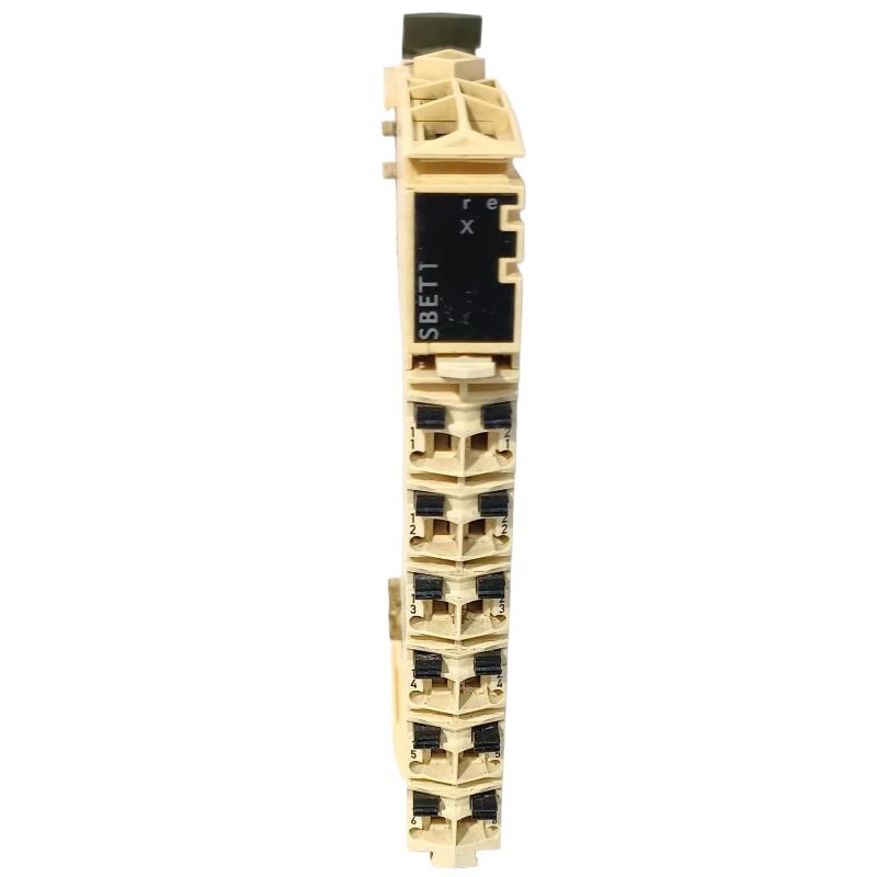
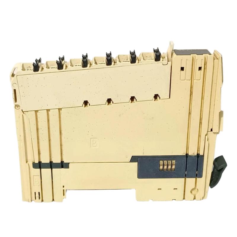
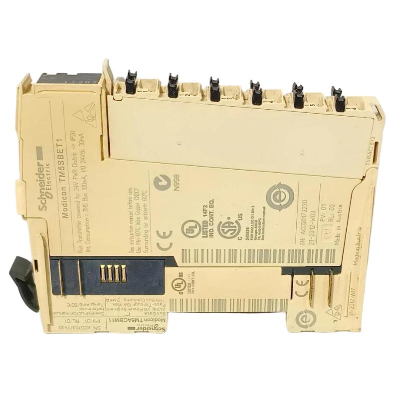
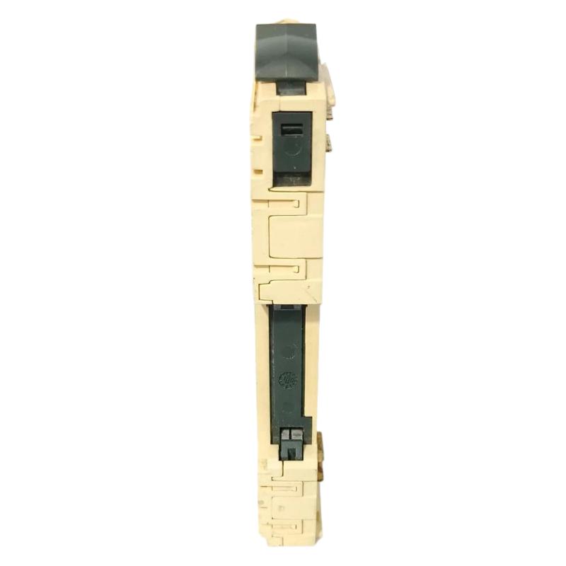
- Schneider
- TM5SBET1
- Remote Transmitter Module
- France
- 99 × 12.5 × 75 mm
- 0.025 kg
- Xiamen, China
- New & In Stock
- T/T, PayPal, Western Union
- 1 Year
- 1-3 Working Days
- DHL, UPS, TNT, FedEx and EMS.
- 24-Hour Service
- COO
- 2
Our advantage

Global Logistics
We have a 10-year logistics and express cooperation agreement, so our products can be shipped to any place in the world.

Brand new and original
Our products are imported in bulk from the place of origin. Because of the cooperative relationship, our products are all original and 100% new.

24-hour service
We provide 7*24 hours service to our customers. We will be there whenever you need us.

Price advantage
All our products are priced very favorably because we have our own warehouse and supply.
| Company Information | |||
| [email protected] | |||
| Mobile | +8615980777398 | ||
| +8615980777398 | |||
| 15980777398 |
1. Product Overview
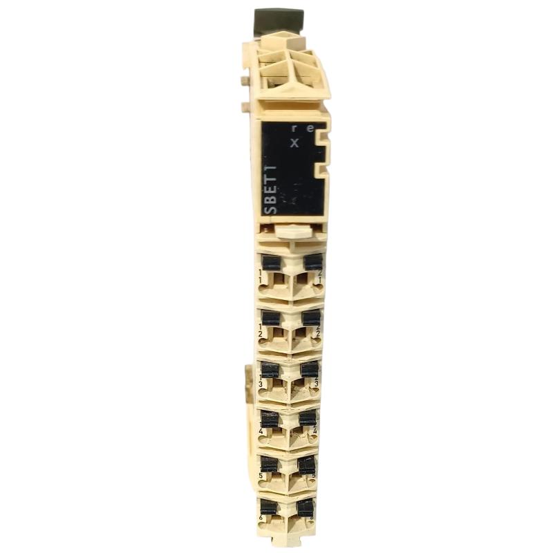
The Schneider TM5SBET1 Remote Transmitter Module is an industrial automation component associated with distributed control and remote I/O integration. In modular automation architectures, transmitter-side components help establish communication or signal exchange between system sections, allowing controllers and remote I/O assemblies to operate as part of a coordinated control system.
Designed for industrial control applications, the TM5SBET1 can be evaluated for use in systems where compact module dimensions, organized wiring, and reliable integration are important. Its listed dimensions of 99 × 12.5 × 75 mm and weight of 0.025 kg make it suitable for installations where cabinet space and component layout require careful planning.
Before installation or replacement, the exact function of the TM5SBET1, its supported communication interface, electrical requirements, and compatibility with the installed hardware configuration should be confirmed against the product label and applicable Schneider Electric technical documentation. These details should not be inferred from the product name alone.
2. Technical Specifications
| Parameter | Specification |
|---|---|
| Brand | Schneider Electric |
| Model | TM5SBET1 |
| Product Type | Remote Transmitter Module |
| Product Family | To be confirmed from the module label and system documentation |
| Dimensions | 99 × 12.5 × 75 mm |
| Weight | 0.025 kg |
| Application | Industrial automation and remote system integration, subject to interface verification |
| Mounting Method | Confirm the approved mounting arrangement for the installed hardware |
| Electrical Requirements | Verify the rated supply and interface requirements before connection |
| Communication Interface | Confirm the supported interface for the exact model |
| System Compatibility | Verify against the controller, base, receiver, and related modules in the existing installation |
The dimensions and weight above are the supplied product specifications. Electrical ratings, supported communication protocols, channel assignments, and compatibility details should be checked before the module is commissioned.
3. Function and Working Principle
A remote transmitter module generally participates in transferring information between sections of an automation system. Depending on the specific product architecture, this may involve communication with a corresponding receiver, an interface assembly, or another designated system component.
In a distributed automation installation, the overall signal path may include a controller, a transmitter-side component, an interconnection or communication medium, a receiver-side component, and remote I/O devices. The controller uses the resulting data to monitor field conditions and execute its control program.
For the TM5SBET1, the exact signal path and operating principle must be confirmed for the specific hardware configuration. The term “transmitter” alone does not establish whether the module transfers communication data, provides a particular expansion interface, or performs another system-specific function.
When reviewing its role in an installed system, engineers should verify the following:
- The intended transmitter and receiver pairing, if applicable.
- The supported interface and connection method.
- The required power supply and electrical limits.
- The permitted module arrangement and installation position.
- Any configuration parameters or status indicators used during commissioning.
- The controller or system software requirements.
Correct identification of these characteristics helps prevent wiring errors, incompatible replacements, and unnecessary troubleshooting.
4. Role in Industrial Automation Systems
Industrial automation systems often distribute control and I/O functions across multiple modules or physical locations. This approach can simplify cabinet organization and make it easier to expand or maintain equipment, provided all components are compatible and configured correctly.
A transmitter-side module may support this architecture by participating in the connection between designated system components. Its practical role depends on the hardware family and the manufacturer’s defined system arrangement.
Distributed Control
In distributed installations, control and field connections may be located in different parts of a machine or process. Properly configured interface components can help maintain the intended relationship between the controller and remote equipment.
Modular System Integration
Modular automation platforms allow engineers to organize components according to application requirements. Correct module selection is essential to ensure that mechanical dimensions, electrical connections, and communication interfaces match the system design.
Maintenance and Equipment Replacement
A clearly identified transmitter module can simplify maintenance planning. When replacing a failed unit, technicians should compare the complete model number, hardware revision where applicable, connector arrangement, and system compatibility rather than relying only on physical appearance.
System Availability
Unexpected interface faults can interrupt data exchange or prevent related equipment from operating normally. Correct installation, inspection, and commissioning procedures help reduce avoidable downtime.
5. Industrial Applications
Subject to confirmation of its exact technical function and compatibility, the TM5SBET1 may be evaluated for suitable industrial automation installations.
Manufacturing Equipment
Automated production lines use modular control hardware to coordinate machine sequences, monitor equipment status, and manage interactions between different control sections. Correctly matched interface components can help maintain communication within the designed architecture.
Packaging Machinery
Packaging systems often combine sensors, actuators, motors, and controller-based sequencing. Reliable integration of the installed automation modules is important for repeatable machine operation and efficient maintenance.
Material Handling Systems
Conveyors, transfer equipment, and sorting systems may use distributed I/O and modular control arrangements. Interface components must be selected according to the system topology and the required connection method.
Process Automation
Industrial process equipment can contain control panels, remote signal assemblies, and distributed instrumentation. The suitability of a transmitter module depends on its verified function, environmental rating, and compatibility with the installed system.
Equipment Modernization
During control-system upgrades, existing modules may need to be replaced or integrated with newer equipment. Before introducing the TM5SBET1 into a modified system, engineers should confirm that the module is supported by the target hardware configuration and that the intended interface remains compatible.
These examples describe potential application environments for appropriately matched automation hardware. They do not establish that the TM5SBET1 is suitable for every application listed.
6. Installation and System Integration
Correct installation is essential for reliable operation. The following workflow provides a general engineering checklist; the model-specific installation instructions and electrical requirements take precedence.
Step 1: Verify the Model
Check the product label and confirm that the complete part number is TM5SBET1. Compare it with the bill of materials, existing module, and system drawings. Do not substitute a visually similar model without checking its function and compatibility.
Step 2: Isolate the Equipment
Before handling the module, place the machine or control system in a safe state and isolate the relevant power sources according to the site’s lockout/tagout procedure. Verify that the equipment is de-energized before disconnecting or installing hardware.
Step 3: Inspect the Module and Mounting Location
Check the module housing, terminals, connectors, and mounting area for visible damage, contamination, or signs of overheating. Confirm that the mounting method and surrounding components meet the requirements for the specific hardware family.
Step 4: Confirm the Electrical and Interface Requirements
Review the approved wiring diagram and identify the correct supply connections, interface connections, and any required companion modules. Never assume terminal assignments, voltage levels, or connector pinouts based solely on the module name.
Step 5: Install the Module
Fit the module using the specified mounting procedure. Ensure that it is securely positioned and that any required mechanical connections are fully engaged. Avoid excessive force, which may damage the housing or connector contacts.
Step 6: Check the System Arrangement
Verify the position of the module in the overall assembly and confirm the intended relationship with the controller, receiver, or other associated hardware. Incorrect positioning or an unsupported combination of modules can prevent the system from starting correctly.
Step 7: Restore Power and Check Status
After completing wiring and inspection, restore power according to the approved commissioning procedure. Observe any available status indicators and check the controller or engineering software for diagnostic messages. Interpret indicators using the documentation for the exact product.
Step 8: Validate System Operation
Confirm that the intended communication or interface function is available. Check related module status, controller diagnostics, and any relevant system data. Complete functional testing before returning the equipment to normal operation.
7. Troubleshooting Common Problems
If a system containing the TM5SBET1 does not operate as expected, troubleshooting should begin with basic installation checks and progress toward configuration and hardware testing.
| Symptom | Possible Causes | Recommended Checks |
|---|---|---|
| Module is not detected | Incorrect installation, incompatible hardware, or a connection problem | Verify the model, mounting, connectors, and supported system arrangement |
| No expected communication or data exchange | Incorrect interface connection, incompatible companion hardware, or configuration error | Check wiring diagrams, interface requirements, and system diagnostics |
| Status indicator shows an abnormal condition | Power, connection, configuration, or hardware fault | Identify the indicator meaning from the applicable technical documentation |
| System reports a configuration error | Unsupported module combination or incorrect configuration | Compare the installed hardware with the approved configuration and project settings |
| Intermittent operation | Loose connection, electrical interference, unstable supply, or environmental issue | Inspect connections and grounding, then evaluate power quality and installation conditions |
| Fault remains after replacement | The original cause may be external to the module | Check associated hardware, cables, power sources, configuration, and controller diagnostics |
7.1 Check Power and Connections
Verify that all required supply connections meet the specified electrical limits. Inspect the relevant connectors and wiring for looseness, damage, contamination, or incorrect termination. Perform electrical measurements only with suitable instruments and according to safe working procedures.
7.2 Confirm Hardware Compatibility
A replacement module may fit physically but still be unsuitable for the installed system. Compare the complete part number and confirm compatibility with the associated modules, controller, interface, and software configuration.
7.3 Review Diagnostic Information
Use the system’s available diagnostic tools to identify whether the issue originates in the module, a related component, or the wider communication path. Record error messages and status indications before changing the configuration.
7.4 Inspect Environmental Conditions
Excessive heat, vibration, moisture, dust, or electrical interference may affect industrial electronics. Confirm that the installation environment meets the product’s specified operating conditions.
7.5 Determine Whether Replacement Is Necessary
If wiring, power, configuration, and associated equipment have been checked but the fault persists, the module may require further testing or replacement. Use an approved replacement and follow the site’s change-control procedure. Do not open or modify the module unless an authorized repair procedure specifically permits it.
8. Maintenance and Reliability Recommendations
Preventive maintenance helps reduce unexpected faults and supports long-term system reliability.
- Inspect connections: Check relevant wiring and connectors during scheduled maintenance.
- Keep the control cabinet clean: Prevent dust accumulation and ensure that ventilation requirements are met.
- Monitor system diagnostics: Record recurring faults and investigate patterns rather than repeatedly resetting alarms.
- Maintain configuration records: Keep accurate drawings, module lists, and controller project backups.
- Control replacement parts: Store modules in suitable conditions and protect connectors from contamination or electrostatic discharge.
- Document hardware changes: Record replacement dates, model numbers, and any changes to the installed configuration.
- Follow approved procedures: Use the manufacturer’s instructions and site safety requirements for installation, testing, and maintenance.
The appropriate maintenance interval depends on the operating environment, system criticality, and site maintenance policy.
9. Compatible System Components
The following table identifies component categories that may need to be checked during system integration. It does not confirm compatibility with any specific part number.
| Component Category | Integration Considerations |
|---|---|
| Controller or CPU | Confirm supported hardware family, firmware, and configuration requirements |
| Receiver or corresponding interface module | Verify the intended pairing and supported connection method, if applicable |
| Base or mounting assembly | Check mechanical fit and the approved module arrangement |
| Communication or interconnection cable | Confirm connector type, pinout, cable specification, and permitted length |
| Power supply | Verify rated voltage, current capacity, and distribution requirements |
| Engineering software | Confirm that the installed hardware and configuration tools support the required setup |
Compatibility should be established using the complete system configuration rather than the product family name alone.
10. Replacement and Alternative Selection
When selecting a replacement for the Schneider TM5SBET1 Remote Transmitter Module, engineers should compare technical function and system compatibility before considering price or physical dimensions.
| Selection Factor | What to Verify |
|---|---|
| Exact model | Confirm TM5SBET1 and any relevant hardware revision |
| Functional role | Ensure the replacement performs the same defined function |
| Electrical characteristics | Compare supply requirements and electrical interface specifications |
| Communication interface | Confirm the supported protocol or connection method |
| Mechanical fit | Check dimensions, mounting arrangement, and connector position |
| System compatibility | Verify the controller, companion modules, and configuration requirements |
| Product condition | Evaluate the condition, testing status, storage history, and warranty of the replacement |
| Commissioning requirements | Determine whether configuration changes or additional validation are required |
A module with similar dimensions or a similar product description is not necessarily a valid substitute. If the original model is unavailable, use an alternative only after confirming its technical equivalence for the intended system.
11. Key Advantages of Correct Module Selection
Although the specific performance characteristics of the TM5SBET1 must be confirmed from its technical documentation, selecting the correct transmitter-side component provides several general benefits in industrial automation.
Improved integration: A correctly matched module supports the intended system architecture and reduces the risk of incompatible connections.
Space-efficient design: The supplied dimensions of 99 × 12.5 × 75 mm help engineers plan cabinet layouts and assess available installation space.
Lightweight construction: With a listed weight of 0.025 kg, the module contributes little mass to the overall assembly. Actual mounting requirements must still be observed.
Simplified maintenance planning: Accurate identification and documentation make it easier to manage spare parts and trace hardware changes.
More systematic troubleshooting: Verified model information and configuration records help maintenance teams isolate faults efficiently.
These benefits depend on correct product identification, suitable installation, and compliance with the system manufacturer’s requirements.
12. Technical FAQs
Q1: What is the Schneider TM5SBET1?
The TM5SBET1 is identified in the supplied product information as a Schneider Remote Transmitter Module. Its exact interface function and system role should be confirmed from the module label and applicable technical documentation.
Q2: What are the dimensions of the TM5SBET1?
The supplied dimensions are 99 × 12.5 × 75 mm.
Q3: How much does the TM5SBET1 weigh?
The supplied product weight is 0.025 kg.
Q4: Can the TM5SBET1 be installed in any Schneider automation system?
No. Physical fit does not establish electrical or functional compatibility. Confirm the supported hardware family, interface, mounting arrangement, and configuration requirements before installation.
Q5: What should be checked before replacing the module?
Verify the complete model number, the intended function, electrical requirements, connectors, associated modules, and system configuration. Record existing diagnostics before removing the original unit.
Q6: Why might a system fail to recognize the module?
Possible causes include an incorrect installation, an incompatible hardware combination, connection problems, power issues, or configuration errors. Check the system’s diagnostic information and the approved installation instructions.
Q7: Does the TM5SBET1 require special software configuration?
Configuration requirements depend on the specific hardware architecture and application. Confirm whether the module requires software settings, controller support, or a defined companion module before commissioning.
Q8: Can a similar transmitter module be used as an alternative?
Only if its functional role, electrical characteristics, interface, mechanical arrangement, and system compatibility are confirmed. Similar naming or dimensions alone are insufficient.
Q9: What should be done if the module continues to report a fault?
Check power, connections, configuration, associated hardware, and diagnostic messages. If the fault persists, follow an approved testing or replacement procedure and avoid modifying the module without authorization.
13. Conclusion
The Schneider TM5SBET1 Remote Transmitter Module is an industrial automation component identified for remote transmitter applications. Its supplied dimensions of 99 × 12.5 × 75 mm and weight of 0.025 kg provide useful information for preliminary equipment identification and cabinet planning.
For dependable operation, engineers should verify the module’s precise function, electrical requirements, interface, and compatibility with the existing automation architecture before installation or replacement. Careful wiring checks, systematic commissioning, diagnostic review, and documented maintenance procedures can help reduce avoidable downtime and support reliable industrial control system operation.