

ProductPRODUCT
Featured products



Contact Us
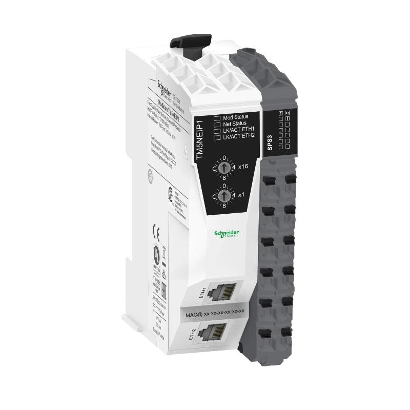
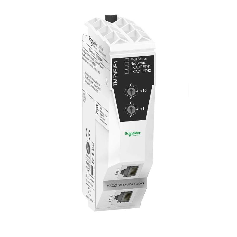
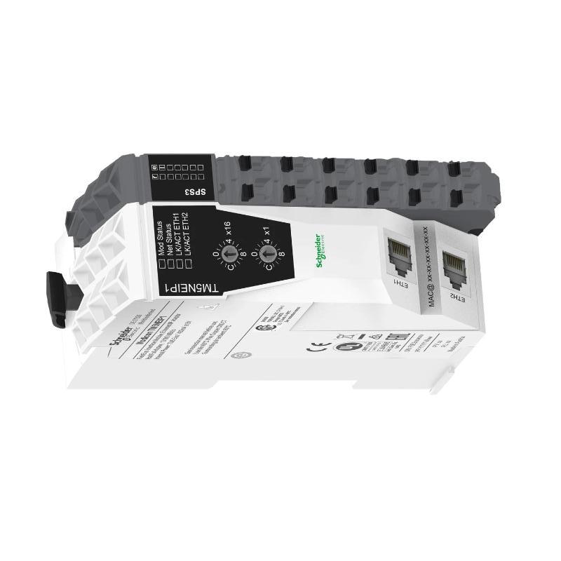
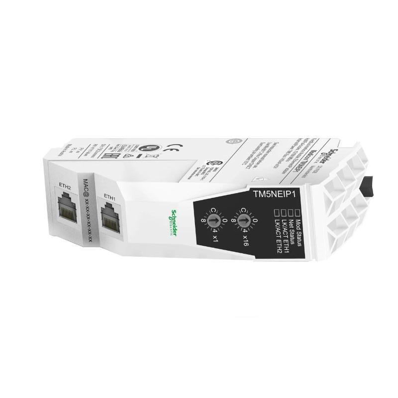
- Schneider
- TM5NEIP1
- Ethernet/IP Fieldbus Interface
- France
- 99 × 25 × 75 mm
- 0.025 kg
- Xiamen, China
- New & In Stock
- T/T, PayPal, Western Union
- 1 Year
- 1-3 Working Days
- DHL, UPS, TNT, FedEx and EMS.
- 24-Hour Service
- COO
- 15
Our advantage

Global Logistics
We have a 10-year logistics and express cooperation agreement, so our products can be shipped to any place in the world.

Brand new and original
Our products are imported in bulk from the place of origin. Because of the cooperative relationship, our products are all original and 100% new.

24-hour service
We provide 7*24 hours service to our customers. We will be there whenever you need us.

Price advantage
All our products are priced very favorably because we have our own warehouse and supply.
| Company Information | |||
| [email protected] | |||
| Mobile | +8615980777398 | ||
| +8615980777398 | |||
| 15980777398 |
Product Overview
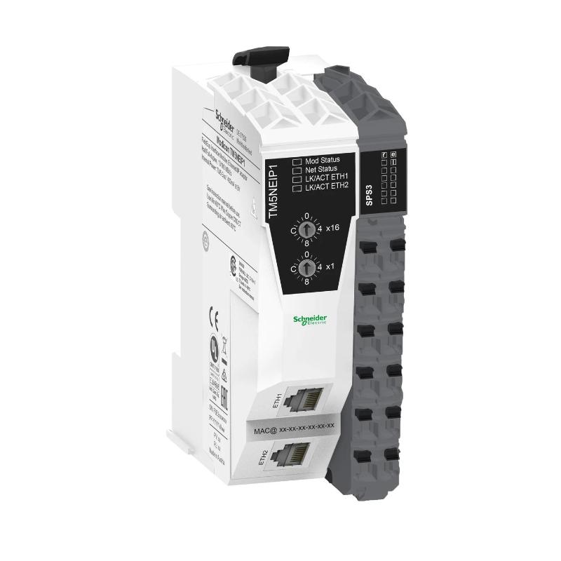
The Schneider Electric TM5NEIP1 Ethernet/IP Fieldbus Interface is an industrial automation communication component designed to support data exchange between compatible control equipment and an EtherNet/IP industrial network. Fieldbus interfaces play an important role in modern automation architectures by connecting controllers, distributed I/O equipment, and other network-enabled devices within a coordinated control system.
In industrial environments, communication between automation components allows controllers to exchange operating data, monitor equipment status, and coordinate machine functions. An Ethernet-based fieldbus interface helps establish the communication path required for this exchange, subject to the capabilities of the specific device and the configuration of the overall network.
The TM5NEIP1 is associated with Schneider Electric’s Modicon TM5 automation product family. Its supplied product designation identifies it as an EtherNet/IP fieldbus interface. The listed dimensions are 99 × 25 × 75 mm, with a listed weight of 0.025 kg. Its compact physical profile can be useful in installations where control-system components must fit into limited cabinet or machine space.
For engineering and procurement purposes, the complete model number should be verified against the device label and the applicable hardware documentation. Supported network roles, controller compatibility, configuration requirements, and connection arrangements should be confirmed for the exact unit before installation.
Technical Specifications
| Parameter | Specification |
|---|---|
| Manufacturer | Schneider Electric |
| Model | TM5NEIP1 |
| Product Type | Ethernet/IP Fieldbus Interface |
| Product Family | Modicon TM5, as identified by the supplied product designation |
| Primary Function | Industrial network communication interface |
| Network Technology | EtherNet/IP, subject to confirmation of the exact hardware specification |
| System Role | Communication interface within a compatible automation architecture |
| Dimensions | 99 × 25 × 75 mm |
| Weight | 0.025 kg |
| Installation | Compatible mounting arrangement; verify the hardware documentation |
| Typical Applications | Machine automation, distributed control, and industrial network integration |
| Compatibility | Confirm against the host controller, TM5 configuration, and network requirements |
The table reflects the supplied product identification and physical data. Specific details such as supported connection types, network roles, communication capacity, configuration software, diagnostic indicators, and compatible controller models should be verified against the exact product documentation rather than assumed from the model name.
What Is the Schneider TM5NEIP1?
The TM5NEIP1 is identified as an EtherNet/IP fieldbus interface used in industrial automation. An interface of this type provides a defined connection between compatible automation hardware and an industrial communication network.
EtherNet/IP is an industrial communication technology based on standard Ethernet infrastructure and the Common Industrial Protocol (CIP). In a suitable system, it can carry control information, status data, and other supported device information between network participants.
The fieldbus interface’s actual role depends on the hardware design. It may be part of a larger controller or distributed I/O arrangement, so engineers should confirm whether the device acts as a network adapter, scanner, communication interface, or another defined role before designing the system.
A simplified communication path is:
Industrial Controller → Compatible Fieldbus Interface → EtherNet/IP Network → Supported Automation Devices
The precise arrangement depends on the configured system architecture and the capabilities of the connected equipment.
Function and Working Principle
1. Industrial Network Connectivity
The primary purpose of an industrial fieldbus interface is to provide a communication path between compatible automation equipment and the network. The interface operates according to its supported hardware and communication configuration.
Before connecting a device, verify its network interface, supported connection arrangement, and role within the control system.
2. Data Exchange
Industrial automation networks allow devices to exchange defined data according to their supported communication services. Depending on the configured architecture, this data may include process values, equipment status, commands, or diagnostic information.
The actual data available through the TM5NEIP1 depends on the connected hardware, configured devices, and supported communication functions.
3. Communication Configuration
Successful network integration requires the devices and controller to use compatible configuration settings. Depending on the system, configuration may involve device identification, network addressing, communication parameters, and the definition of data exchanged between devices.
The required settings should be established using the applicable Schneider Electric engineering documentation.
4. Controller Integration
A fieldbus interface becomes useful when the controller can interpret the information exchanged through the network. The control program may use available data to coordinate equipment, monitor operating conditions, and execute machine sequences.
The interface provides communication functionality; it does not independently determine the application’s control logic.
5. Network Diagnostics
When supported by the hardware and engineering environment, network diagnostics can help identify connection problems, configuration mismatches, and communication interruptions.
Reviewing the interface status and controller diagnostic information can shorten troubleshooting time and help maintenance personnel distinguish network faults from application-level problems.
Role in Industrial Control Systems
In an industrial automation architecture, communication interfaces connect otherwise separate components into a coordinated system. A controller may need information from distributed I/O, machine modules, or other compatible network devices to execute its programmed operations.
The TM5NEIP1’s stated fieldbus-interface role makes network integration and device communication the key areas to verify when considering this product.
| System Component | Typical Function |
|---|---|
| PLC or Machine Controller | Executes the automation program |
| TM5NEIP1 Fieldbus Interface | Provides the specified fieldbus communication function |
| Compatible I/O Equipment | Acquires field signals or controls outputs |
| EtherNet/IP Network | Carries supported industrial communication data |
| Network Switch | Connects network devices where required by the design |
| HMI or Operator Interface | Displays operating status and alarms |
| Engineering Workstation | Supports configuration, monitoring, and diagnostics |
| Field Devices | Provide sensor signals or receive control commands through the associated I/O system |
Not every component listed is necessarily required in every installation. The final architecture should follow the controller’s supported configuration and the interface’s documented capabilities.
Industrial Applications
Machine Automation
Industrial machines often require communication between controllers, I/O systems, and other network-enabled components. A compatible fieldbus interface can support this communication architecture, helping coordinate machine operations and provide access to device status.
Distributed I/O Systems
Where an automation architecture uses distributed I/O, network communication allows the controller to exchange information with remote or locally distributed I/O equipment. The specific suitability of the TM5NEIP1 for a given arrangement must be confirmed from the supported system configuration.
Packaging Equipment
Packaging machinery frequently combines sensors, actuators, motion equipment, and controller logic. Industrial networking can help coordinate these components and make operating information available to the controller.
Material Handling Systems
Conveyors, transfer stations, and handling equipment may rely on networked control components to coordinate movement and exchange status data. A compatible communication interface can form part of this architecture.
Assembly and Production Lines
Production lines commonly use several control devices that must operate in sequence. Industrial communication enables the exchange of supported information between system components, improving coordination and facilitating centralized monitoring.
Industrial Equipment Monitoring
Network-connected automation devices can make status and diagnostic data available to other parts of the control system. When supported by the installed equipment, this information can help operators recognize communication faults and equipment abnormalities.
Installation and System Integration
Correct installation begins with confirming the interface’s identity, supported network role, and compatibility with the host automation system.
Verify the Product Identification
Check the complete TM5NEIP1 model designation and compare it with the existing hardware records. Verify the product revision and intended function before mounting or connecting the device.
Do not assume that similarly sized TM5 components are interchangeable. Different modules within the same product family may have different electrical, communication, and configuration requirements.
Confirm Controller Compatibility
Before integrating the interface, establish whether the host controller and installed engineering software support the device. Confirm the required firmware, hardware configuration, and any necessary system components.
If the unit is being used as a replacement, compare the original and replacement identifiers and review any configuration changes required by the applicable documentation.
Prepare the Installation Environment
Install the device using the specified mounting arrangement. Allow sufficient room for wiring, connector access, inspection, and maintenance.
Keep the control cabinet within the environmental limits specified for the installed equipment. Protect the interface from excessive dust, moisture, vibration, and temperature conditions that could impair reliable operation.
Connect the Network
Use the documented network connection method and suitable industrial Ethernet cabling and accessories. Confirm the connection arrangement and cable requirements for the exact device.
Where the installation includes multiple network devices, document the network topology and device identification information. Avoid introducing unapproved network connections or configuration changes into an operating control system.
Configure Communication Parameters
Apply the settings required by the supported controller and network architecture. Depending on the system, this may include device identification, IP addressing, communication configuration, and data mapping.
Use the correct engineering tools and hardware descriptions for the verified product. Avoid copying settings from another device unless compatibility has been established.
Commission the Network
After installation, check the physical connection and the device’s available status indications. Verify that the controller recognizes the configured hardware and that expected communication data is available.
Test the relevant application functions before returning the machine to normal operation. Record the configuration, device identifiers, and commissioning results for future maintenance.
Troubleshooting the TM5NEIP1 Fieldbus Interface
Communication problems can originate in the interface, the network cabling, the connected equipment, the controller configuration, or the broader network architecture. A structured approach helps identify the actual cause.
Network Communication Is Unavailable
Possible causes include:
- Disconnected or damaged network cabling
- Incorrect network connection
- Missing or unsuitable device power
- Incorrect configuration
- Unsupported controller or device combination
- Addressing conflict
- Fault in another network component
Begin by checking the device’s power and physical connections. Review available status indicators and controller diagnostics, then verify the configured device identity and network settings.
Intermittent Communication
Intermittent communication may result from loose connectors, damaged cables, electrical interference, unstable power, network congestion, or configuration problems elsewhere in the system.
Inspect the cabling and connectors, review network diagnostics where available, and determine whether the problem affects one device or several devices on the network.
Controller Does Not Recognize the Interface
A controller may fail to recognize a device when the hardware configuration is incorrect, the selected device entry does not match the physical unit, or the installed controller or engineering software does not support the configuration.
Verify the complete model number, hardware selection, firmware requirements, and system compatibility before replacing the interface.
Data Is Missing or Incorrect
If communication appears active but the application receives missing or unexpected data, inspect the data mapping, configured device relationships, and controller program. Confirm that the correct data items are being read and interpreted.
A functioning physical network does not necessarily mean that application data has been configured correctly.
Repeated Network Faults
Recurring communication alarms should be investigated using diagnostic information and a record of the conditions under which the faults occur.
Check for repeated cable interruptions, unstable power, device configuration changes, or faults affecting multiple network participants. Replace hardware only after external connections and configuration issues have been investigated.
Maintenance Recommendations
Regular inspection helps maintain stable communication and simplifies future fault diagnosis.
Inspect network cables and connectors. Look for damaged insulation, loose connections, contamination, and signs of mechanical stress.
Review diagnostic records. Record recurring communication errors and note whether they affect one device or several network participants.
Maintain configuration records. Keep an accurate copy of the network topology, device identities, addressing plan, and controller configuration.
Protect the installation environment. Maintain the environmental conditions required by the equipment and ensure that cables are routed appropriately.
Check connector seating. During approved maintenance windows, inspect the physical connections and verify that they are secure.
Use controlled replacement procedures. Before replacing the interface, record the existing model number and configuration. Follow the system’s shutdown, isolation, and handling procedures.
Maintenance should be performed in accordance with the requirements of the installed hardware and the operating environment.
Compatible System Components
The TM5NEIP1 should be integrated only with equipment confirmed to support the intended hardware and network configuration. The following table describes general component categories that may be relevant to an industrial Ethernet-based automation system.
| Component Category | Purpose |
|---|---|
| Compatible Schneider Electric Controller | Executes control logic and manages supported system communication |
| Compatible Modicon TM5 Modules | Provide the I/O or system functions supported by the selected configuration |
| Industrial Ethernet Cabling | Connects compatible network devices |
| Ethernet Network Switch | Provides network connectivity where required |
| HMI Panel | Presents machine status and operator controls |
| Engineering Software | Supports device configuration and diagnostics |
| Industrial Power Supply | Supplies appropriately rated power to the applicable equipment |
| Networked Automation Devices | Exchange supported data within the configured architecture |
This list describes possible system roles rather than guaranteed direct compatibility. Exact model combinations and required accessories must be verified before procurement or installation.
Replacement and Procurement Considerations
When sourcing the Schneider Electric TM5NEIP1, confirm the full model designation and compare the unit with the existing installation. The product description, system role, and physical specifications should all be consistent with the intended application.
Important checks include:
- Complete model number and product revision
- Supported communication technology and device role
- Compatible controller and hardware configuration
- Required engineering software or firmware
- Network connector and cabling requirements
- Mounting and installation arrangement
- Environmental requirements
- Condition and traceability of the supplied unit
The listed dimensions are 99 × 25 × 75 mm, and the listed weight is 0.025 kg. These values are useful for preliminary space planning, inventory records, and shipping calculations, but they do not establish electrical or functional compatibility.
For a replacement installation, retain the original network settings and controller configuration where appropriate, but verify that they remain valid for the replacement hardware. Commission the network and confirm application-level data exchange before returning the equipment to service.
Key Advantages
Industrial Communication Integration
A compatible fieldbus interface provides a structured communication path between automation equipment and the supported industrial network.
Support for Coordinated Control
Networked control components can exchange supported status and operating information, allowing the controller to coordinate connected equipment.
Compact Physical Design
The supplied dimensions of 99 × 25 × 75 mm and weight of 0.025 kg indicate a compact form factor that may be useful where installation space is limited.
Easier Network Diagnosis
When the hardware and engineering environment provide suitable diagnostics, communication status information can help maintenance personnel investigate network problems.
Integration into a Documented Automation Architecture
Correct identification, configuration, and commissioning allow the interface to be managed as part of a larger industrial control system.
Technical FAQs
What is the Schneider TM5NEIP1?
The TM5NEIP1 is identified in the supplied product description as an Ethernet/IP fieldbus interface associated with industrial automation and the Modicon TM5 product family.
What is the primary function of a fieldbus interface?
A fieldbus interface provides the communication function required for compatible automation devices to exchange supported data over an industrial network.
What are the dimensions of the TM5NEIP1?
The supplied dimensions are 99 × 25 × 75 mm.
What is the listed weight?
The supplied weight is 0.025 kg.
Does the TM5NEIP1 support EtherNet/IP?
The supplied product name identifies it as an Ethernet/IP fieldbus interface. Confirm the exact supported network functions and device role against the applicable hardware documentation before system design or commissioning.
Which PLC can be used with this interface?
The compatible controller depends on the exact hardware configuration and the manufacturer’s supported system architecture. Confirm controller, software, and firmware compatibility before connecting the device.
What should be checked if communication fails?
Inspect power, cables, connectors, network settings, hardware configuration, controller compatibility, and diagnostic messages. Also determine whether the fault affects only the interface or multiple network devices.
Can another TM5 module replace the TM5NEIP1?
Not automatically. Modules within the same product family may have different functions and electrical interfaces. A replacement must be verified against the exact part number, communication role, and host-system requirements.
Conclusion
The Schneider Electric TM5NEIP1 Ethernet/IP Fieldbus Interface is intended to provide industrial communication functionality within a compatible automation architecture. Fieldbus interfaces help connect control equipment and networked devices, allowing supported status and operating data to be exchanged for monitoring and coordinated machine operation.
With supplied dimensions of 99 × 25 × 75 mm and a listed weight of 0.025 kg, the device has a compact physical profile for suitable automation installations. Successful integration depends on accurate product identification, verified controller compatibility, correct network configuration, reliable cabling, and thorough commissioning.
Before purchasing or installing the TM5NEIP1, verify its precise network role and supported hardware configuration. Proper integration and documented maintenance help keep industrial communication reliable and simplify troubleshooting throughout the equipment’s service life.