

ProductPRODUCT
Featured products



Contact Us
- Schneider
- SR3B262BD
- Modular Smart Relay
- France
- 124.6 x 107.6 x 59.5 mm
- 0.3 kg
- Xiamen, China
- New & In Stock
- T/T, PayPal, Western Union
- 1 Year
- 1-3 Working Days
- DHL, UPS, TNT, FedEx and EMS.
- 24-Hour Service
- COO
- 15
Our advantage

Global Logistics
We have a 10-year logistics and express cooperation agreement, so our products can be shipped to any place in the world.

Brand new and original
Our products are imported in bulk from the place of origin. Because of the cooperative relationship, our products are all original and 100% new.

24-hour service
We provide 7*24 hours service to our customers. We will be there whenever you need us.

Price advantage
All our products are priced very favorably because we have our own warehouse and supply.
| Company Information | |||
| [email protected] | |||
| Mobile | +8615980777398 | ||
| +8615980777398 | |||
| 15980777398 |
Product Overview
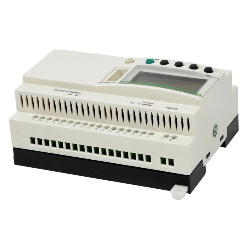
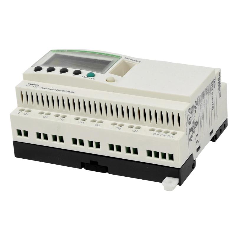
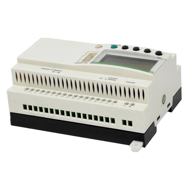
The Schneider Electric SR3B262BD Modular Smart Relay is a compact programmable control device designed for small-scale automation tasks that require flexible logic control, equipment monitoring, and straightforward integration with electrical control systems. As part of Schneider Electric’s Zelio Logic smart relay family, the SR3B262BD is intended for applications where conventional relay circuits can be replaced or simplified through programmable logic.
A modular smart relay combines control logic and input/output functionality in a compact device. Instead of relying entirely on interconnected auxiliary relays, timers, and counters, engineers can configure a control program to process input conditions and determine the required output states. This approach can reduce wiring complexity, simplify modifications, and make routine control functions easier to maintain.
The SR3B262BD can be considered for suitable applications involving lighting control, ventilation, pumps, small machinery, equipment sequencing, and other local automation tasks. Its exact electrical ratings, input/output configuration, expansion compatibility, and programming requirements should be confirmed against the complete product reference and applicable hardware documentation before installation.
The supplied physical specifications identify the Schneider SR3B262BD with dimensions of 124.6 × 107.6 × 59.5 mm and a weight of approximately 0.3 kg. These measurements are useful for preliminary cabinet-layout planning and replacement identification.
Technical Specifications
| Parameter | Specification |
|---|---|
| Manufacturer | Schneider Electric |
| Model | SR3B262BD |
| Product Family | Zelio Logic, subject to exact catalog verification |
| Product Type | Modular Smart Relay |
| Primary Function | Programmable logic control for small automation applications |
| Control Method | User-configured relay logic program |
| Input Function | Monitoring compatible field signals |
| Output Function | Switching compatible control loads or interface devices |
| Programming | Confirm the supported programming method and software version |
| Expansion Capability | Verify compatible expansion modules for the exact model |
| Dimensions | 124.6 × 107.6 × 59.5 mm |
| Weight | 0.3 kg |
| Installation | Electrical control cabinet or specified mounting arrangement |
| Typical Applications | Lighting, ventilation, small machines, pumps, and local control panels |
Specification note: The dimensions and weight above are based on the supplied product information. The suffix in the model number is important when identifying a smart relay, so the rated supply voltage, input type, output arrangement, terminal assignment, and expansion options should be checked against the exact SR3B262BD catalog record before wiring.
What Is the Schneider SR3B262BD Modular Smart Relay?
A modular smart relay is a programmable control device positioned between conventional hardwired relay circuits and more extensive PLC-based automation systems. It is generally used when a machine or electrical installation requires a defined set of logic operations but does not need the full complexity of a large automation controller.
Traditional control circuits often use separate relays, time-delay relays, counters, and interlocking contacts. When the operating sequence changes, the circuit may need to be rewired. A programmable smart relay can consolidate many of these functions into a configurable control program.
For example, a ventilation system might need to start a fan when a control condition is met, maintain operation for a specified interval, and stop when another condition occurs. A smart relay can process the connected input signals and apply the programmed timing and interlocking logic.
The general control sequence is:
Field Inputs → Smart Relay Logic → Output Switching → Controlled Equipment
The actual behavior depends on the installed model, the connected field devices, and the user’s program.
Function and Working Principle
1. Input Signal Acquisition
The smart relay receives compatible signals from field devices and operator controls. Depending on the application and supported input configuration, these may include push buttons, selector switches, limit switches, float switches, and suitable sensor outputs.
Each input represents a condition that the control program can evaluate. For example, an input may indicate that a machine door is closed, a tank has reached a level threshold, or an operator has requested a particular operating mode.
Field devices must be compatible with the relay’s electrical input requirements. Signal voltage, polarity, common-terminal arrangement, and wiring configuration should be confirmed before connection.
2. Programmed Logic Processing
The control program evaluates input states and applies the required logical operations. Typical smart-relay functions can include Boolean logic, timers, counters, sequencing, and interlocking, depending on the model and available programming features.
A simple application might require two conditions to be true before a motor starter can receive a run command. Another may use a timer to keep a light on for a defined period after a push button is activated.
The program determines how the smart relay responds; the device should not be assumed to contain a particular application sequence until it has been configured and tested.
3. Output Control
After processing the program, the relay updates its outputs according to the defined logic. These outputs may operate compatible control circuits, indicator lamps, interface relays, or other loads within the device’s electrical ratings.
For inductive or high-current loads, an appropriately rated interface relay or contactor may be necessary. The smart relay’s output capacity must not be exceeded.
4. Timing and Sequencing
Many small automation tasks require operations to occur in a specific order or after a delay. Depending on the supported functions, a smart relay can simplify these tasks by incorporating timing and sequence logic into the program.
Examples include delayed fan shutdown, timed lighting, staged equipment operation, and automatic restart sequences where permitted by the machine design.
5. Local Control and Maintenance
A smart relay can provide a centralized location for simple control logic. Maintenance personnel can use the program, wiring records, and available status indicators to trace the sequence of operation and identify potential input, output, or configuration problems.
The available diagnostic and programming features depend on the exact model and installation.
Role in Industrial Control Systems
The SR3B262BD can serve as a local controller for an electrical panel or small machine when the required functions match the device’s verified capabilities. Its role is to process input conditions and operate control outputs according to a defined program.
In a typical installation, the smart relay works with power supplies, operator controls, field switches, protection devices, contactors, and the equipment being controlled.
| System Component | Typical Function |
|---|---|
| Modular Smart Relay | Executes configured control logic |
| Push Buttons | Provide operator commands |
| Selector Switches | Select operating modes |
| Limit Switches | Detect mechanical position |
| Float or Level Switches | Provide discrete level indications |
| Interface Relays | Adapt switching interfaces where required |
| Contactors | Switch suitable motor or power circuits |
| Circuit Protection | Protects wiring and equipment as designed |
| Indicator Lamps | Display operating status |
| Electrical Enclosure | Houses and protects the control equipment |
The smart relay is only one part of the overall control system. Correct protection, electrical isolation, grounding, and load selection remain essential.
Industrial Applications
Lighting Automation
The SR3B262BD may be suitable for lighting-control tasks that require scheduled switching, timed operation, or logic based on several discrete conditions. Application design must account for the lighting load, inrush current, and output switching ratings.
Ventilation and Fan Control
Small ventilation systems may require fan start/stop logic, operating interlocks, delayed shutdown, or status monitoring. A smart relay can implement these functions when the required input/output configuration is supported.
Pump Control
For suitable pump installations, programmable logic can coordinate start/stop requests, level-switch conditions, and basic operating sequences. Pump motor power should normally be switched through correctly rated motor-control equipment rather than directly through an undersized relay output.
Small Machinery
Compact machines often require a limited number of discrete inputs and outputs to manage operator commands, position switches, cycle timing, and actuator sequencing. A smart relay can provide a practical control platform when the machine’s functional and safety requirements are met.
Building and Facility Control
Small facility-control panels may use smart relays for basic ventilation, lighting, utility equipment, or other discrete automation functions. Integration should be evaluated according to the required electrical interfaces and control sequence.
General Electrical Panels
Smart relays can simplify repetitive switching and timing functions in auxiliary control panels. Their use can reduce the number of separate control components and make certain logic changes easier to implement.
Installation and System Integration
Correct installation begins with verifying the complete model reference and confirming that the device is suitable for the intended electrical application.
Confirm the Model and Supply Requirements
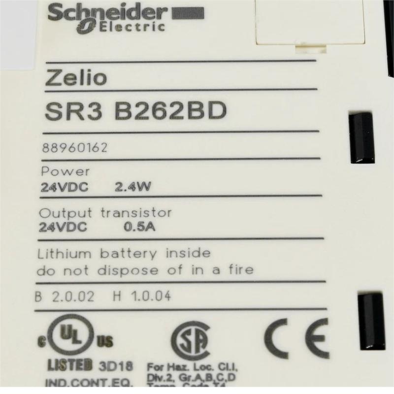
Check the label for the full SR3B262BD designation. Verify the rated supply voltage, permissible operating conditions, terminal arrangement, and applicable wiring diagram.
Do not infer the supply voltage or output type from the product family alone. Variants with similar model numbers can have different electrical characteristics.
Plan the Control Panel
The supplied dimensions are 124.6 × 107.6 × 59.5 mm. Allow additional space for terminal wiring, cable bending, ventilation, access, and maintenance.
Mount the unit using the specified method and ensure that the enclosure provides suitable protection from dust, moisture, vibration, and excessive temperature.
Connect Input Devices
Wire push buttons, switches, sensors, and other input devices according to the model’s verified terminal diagram. Label conductors and record each signal’s purpose.
Check the electrical compatibility of every connected device before applying power. Incorrect wiring or incompatible signal voltage may prevent proper operation or damage the equipment.
Connect Output Circuits
Verify the output type and rated switching capacity before connecting loads. Consider the load’s steady-state current, inrush current, inductive characteristics, and switching frequency.
Use properly rated contactors or interface relays when required. Provide suitable circuit protection and suppression components in accordance with the load manufacturer’s requirements and the control-panel design.
Develop and Verify the Program
Create the required control logic using the programming method supported by the exact model. Organize the program so that operating conditions, interlocks, timer functions, and fault responses are easy to understand.
Before connecting the equipment to a live process, test the program using an approved commissioning procedure. Verify normal operation, abnormal input conditions, power interruption behavior, and restart behavior.
Commission the Installation
During commissioning:
- Confirm the supply and protective arrangements.
- Check terminal tightness and wiring labels.
- Verify each input against the corresponding field device.
- Test each output with the intended control circuit.
- Confirm timer settings and sequence transitions.
- Verify that interlocks operate as designed.
- Record the final program version and wiring configuration.
Safety-related functions must be designed and validated using an appropriate safety architecture. A standard smart relay should not be treated as a safety controller unless the exact product is explicitly certified and suitable for that purpose.
Troubleshooting the SR3B262BD Modular Smart Relay
When a control sequence fails, inspect the power supply, field wiring, program logic, and output circuit as a complete system.
The Smart Relay Does Not Power Up
Possible causes include an incorrect supply voltage, missing power, loose terminals, a tripped protective device, or a damaged unit.
Verify the rated supply requirements from the exact model documentation. Check the supply and terminal connections using approved electrical procedures before considering replacement.
Inputs Do Not Change State
If the program does not detect a push button or sensor, inspect the field device, its supply, the wiring, terminal assignment, and the input’s electrical compatibility.
Confirm whether the signal reaches the designated input terminal. If the electrical signal is correct but the program does not respond, review the input address and logic conditions.
Outputs Do Not Operate
An output may fail to activate because the required logic conditions are not satisfied, the program is incorrect, the output circuit is open, or the connected load exceeds the permitted rating.
Check the program state and output status first. Then inspect the downstream wiring, protective devices, interface relays, contactors, and load.
Timers or Sequences Behave Incorrectly
Incorrect timing or sequence behavior may result from unsuitable timer settings, unexpected input transitions, logic errors, or incorrect assumptions about the required operating sequence.
Review the program step by step and compare actual input states with the intended conditions. Test changes under controlled conditions before returning the equipment to service.
Intermittent Operation
Intermittent faults may be caused by loose terminals, damaged wiring, unstable supply conditions, electrical interference, failing field devices, or a defective output load.
Inspect connections and the installation environment. If the problem occurs only when a motor, solenoid, or other inductive load switches, examine the circuit design and the suitability of suppression and interface components.
Program or Configuration Problems
If the relay operates differently after maintenance or replacement, verify that the correct program and settings have been restored. Confirm that the replacement device has the same required functionality and electrical configuration.
Keep a controlled backup of the application program and record any changes made during troubleshooting.
Maintenance Recommendations
Regular inspection helps improve the reliability of the smart relay and its associated control circuits.
Inspect terminals and wiring: Look for loose connections, damaged insulation, corrosion, or signs of overheating.
Check field devices: Confirm that switches and sensors operate consistently and provide the expected signals.
Review output loads: Verify that contactors, interface relays, and other loads operate within their ratings.
Maintain program records: Keep a copy of the approved program, parameter settings, and input/output descriptions.
Monitor environmental conditions: Maintain the enclosure within the specified operating environment and prevent excessive dust, moisture, and vibration.
Test control sequences: Periodically verify normal operation, interlocks, timing, and recovery after an interruption according to the site’s maintenance plan.
Maintenance frequency should reflect operating conditions, equipment criticality, and the manufacturer’s requirements.
Compatible System Components
The SR3B262BD may be integrated with other control-panel components when their electrical ratings and functional requirements are compatible.
| Component Type | Application |
|---|---|
| Compatible Control Power Supply | Provides the required control-system supply |
| Push Buttons and Selector Switches | Provide operator commands |
| Limit and Level Switches | Provide discrete feedback |
| Interface Relays | Adapt control outputs to external circuits |
| Contactors | Switch suitable motor and power loads |
| Circuit Breakers and Fuses | Provide appropriate circuit protection |
| Terminal Blocks | Organize field connections |
| Indicator Lamps | Display operating conditions |
| Electrical Enclosure | Provides environmental and physical protection |
| Programming Tools | Support application development and maintenance |
Compatibility should be verified for the exact model, particularly when selecting expansion modules, communication accessories, programming cables, or replacement devices. Similar appearance does not guarantee interchangeability.
Replacement and Procurement Considerations
When purchasing or replacing the Schneider SR3B262BD Modular Smart Relay, check the full reference against the existing installation and the control-system documentation.
Important considerations include:
- Complete model number and product identification
- Supply voltage and electrical requirements
- Input configuration and signal compatibility
- Output type and switching ratings
- Programming method and software support
- Expansion requirements, if applicable
- Mounting and terminal configuration
- Physical condition and inspection records
The supplied dimensions of 124.6 × 107.6 × 59.5 mm and weight of 0.3 kg can assist with inventory management, shipping preparation, and cabinet planning.
Before removing an existing unit, document its wiring, input/output assignments, and application program. After replacement, verify the hardware configuration and test the full control sequence rather than relying solely on the fact that the replacement powers up.
Key Advantages
Programmable Control in a Compact Unit
A smart relay can consolidate suitable logic functions in one device, reducing dependence on separate timers, counters, and auxiliary control relays.
Flexible Sequence Management
Programmed logic can support repeatable operating sequences and make certain control modifications easier than rewiring a conventional relay circuit.
Simplified Troubleshooting
Clearly documented input/output assignments and a well-structured program can help maintenance personnel identify faults more efficiently.
Suitable for Small Automation Tasks
Smart relays are useful where control requirements are limited and a full-scale PLC system may be unnecessary, provided that the device meets the required electrical and functional specifications.
Compact Installation Footprint
The supplied dimensions of 124.6 × 107.6 × 59.5 mm support preliminary planning for control panels with limited available space.
Technical FAQs
What is the Schneider SR3B262BD?
The SR3B262BD is identified as a modular smart relay used for programmable logic control in suitable small-scale automation applications.
What does a modular smart relay do?
It receives compatible input signals, evaluates a configured program, and updates its outputs to control connected equipment or interface circuits.
What are the dimensions of the SR3B262BD?
The supplied dimensions are 124.6 × 107.6 × 59.5 mm.
How much does the SR3B262BD weigh?
The supplied weight is approximately 0.3 kg.
Can it control a motor directly?
Motor-control suitability depends on the verified output type and switching ratings. In many applications, a smart relay operates a properly rated contactor or interface relay rather than switching motor power directly.
Is it suitable for pump and ventilation control?
It may be suitable for basic pump or ventilation logic when the required inputs, outputs, timing functions, and electrical ratings match the application. Protective and safety requirements must be addressed separately.
What should be checked before replacing the relay?
Verify the complete model number, supply requirements, input/output configuration, terminal arrangement, program compatibility, and any expansion or accessory requirements.
What causes a smart relay to stop controlling equipment?
Potential causes include power-supply problems, incorrect wiring, faulty field devices, program errors, output-circuit faults, incompatible loads, or a hardware failure. Troubleshooting should examine the complete control path.
Conclusion
The Schneider Electric SR3B262BD Modular Smart Relay is a compact programmable control solution for suitable industrial and building-automation tasks. By processing discrete field signals and executing configured logic, a smart relay can simplify switching operations, timing functions, and equipment sequencing while reducing the complexity of conventional hardwired control circuits.
With supplied dimensions of 124.6 × 107.6 × 59.5 mm and a weight of approximately 0.3 kg, the SR3B262BD is suited to consideration for compact control-panel installations where its verified electrical and functional specifications meet the application requirements.
Reliable performance depends on correct model identification, compatible field devices, properly rated output circuits, accurate program configuration, and systematic commissioning. Confirming the exact product specifications before installation or replacement helps ensure that the smart relay operates safely and consistently within the intended automation system.