

ProductPRODUCT
Featured products



Contact Us
- Schneider
- SR3B261JD
- Modular Smart Relay
- France
- 124.6 x 107.6 x 59.5 mm
- 0.4 kg
- Xiamen, China
- New & In Stock
- T/T, PayPal, Western Union
- 1 Year
- 1-3 Working Days
- DHL, UPS, TNT, FedEx and EMS.
- 24-Hour Service
- COO
- 16
Our advantage

Global Logistics
We have a 10-year logistics and express cooperation agreement, so our products can be shipped to any place in the world.

Brand new and original
Our products are imported in bulk from the place of origin. Because of the cooperative relationship, our products are all original and 100% new.

24-hour service
We provide 7*24 hours service to our customers. We will be there whenever you need us.

Price advantage
All our products are priced very favorably because we have our own warehouse and supply.
| Company Information | |||
| [email protected] | |||
| Mobile | +8615980777398 | ||
| +8615980777398 | |||
| 15980777398 |
Product Overview
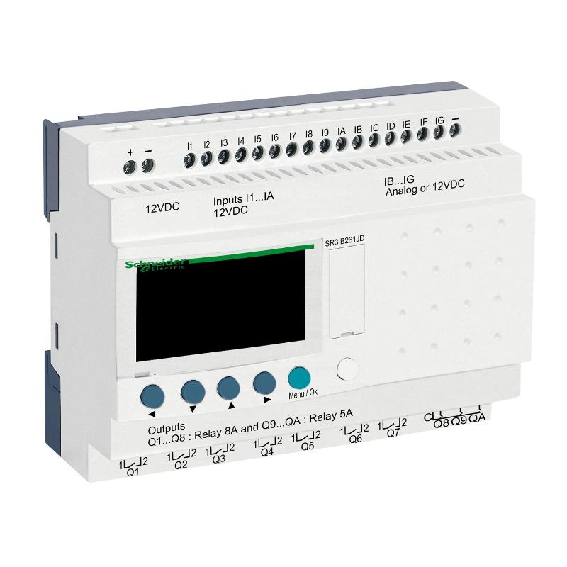
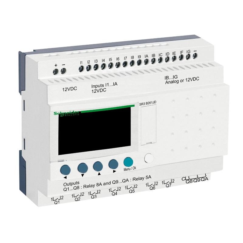
The Schneider Electric SR3B261JD Modular Smart Relay is an industrial control device designed to support compact automation tasks involving discrete signals, programmed logic, and coordinated equipment operation. Modular smart relays are commonly used in small machines, utility systems, building services, and standalone control panels where straightforward automation is required without the complexity of a larger programmable logic controller (PLC).
A smart relay combines control logic with input and output interfaces in a compact device. Depending on the exact model configuration, it can process signals from switches, sensors, and operator controls, then execute programmed instructions to operate connected equipment. Typical applications include lighting control, pump sequencing, ventilation, small conveyor systems, and machine status monitoring.
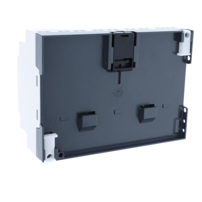
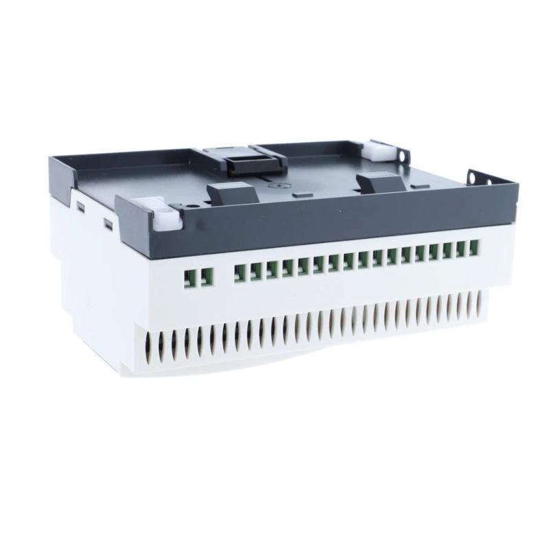
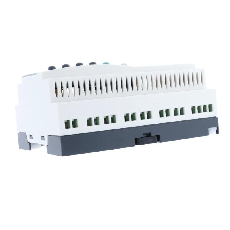
The SR3B261JD belongs to Schneider Electric’s Zelio Logic smart-relay product family according to its supplied product designation. Its listed dimensions are 124.6 × 107.6 × 59.5 mm, with a weight of approximately 0.4 kg. This form factor supports integration into suitable electrical control cabinets where space, straightforward wiring, and maintainability are important.
Before installation or replacement, confirm the complete reference, supply requirements, input and output configuration, and supported programming method against the device label and applicable product documentation. These details are important because smart relays with similar appearances may have different electrical specifications and output types.
Technical Specifications
| Parameter | Specification |
|---|---|
| Manufacturer | Schneider Electric |
| Model | SR3B261JD |
| Product Type | Modular Smart Relay |
| Product Family | Zelio Logic, subject to confirmation of exact reference |
| Primary Function | Compact programmable logic control |
| Control Role | Processing discrete signals and executing programmed logic |
| Input Type | Verify the exact electrical input configuration |
| Output Type | Verify the installed model’s output configuration |
| Programming | Confirm supported programming method for this reference |
| Dimensions | 124.6 × 107.6 × 59.5 mm |
| Weight | 0.4 kg |
| Installation | Suitable control-panel mounting arrangement, subject to product requirements |
| Typical Applications | Small-machine automation, lighting, pumps, ventilation, and utility control |
The physical specifications above are based on the supplied product information. The exact supply voltage, number of input and output points, output ratings, communication capabilities, and expansion compatibility should be verified before engineering or purchasing decisions are made.
What Is the Schneider SR3B261JD Modular Smart Relay?
A modular smart relay is a compact programmable controller used to automate relatively simple electrical and mechanical processes. It occupies a position between conventional relay logic and more extensive PLC-based automation.
In a traditional relay-control circuit, individual relays, timers, and auxiliary contacts are wired together to implement the required sequence. A smart relay can consolidate many of these functions into a programmable device, reducing the need for extensive hardwired logic and making certain control changes easier to implement.
The SR3B261JD is identified as a modular smart relay. In a suitable system, it can receive compatible input signals, evaluate programmed conditions, and change its outputs according to the configured logic.
A simplified control sequence is:
Field Inputs → Smart Relay Logic → Output Commands → Controlled Equipment
For example, a pump-control application might use a level switch as an input and a relay output to command a pump contactor. The smart relay can apply programmed conditions to determine when a start or stop command is issued. Actual implementation depends on the selected hardware, electrical ratings, and application requirements.
Function and Working Principle
1. Input Signal Acquisition
The smart relay receives signals from connected field devices. These may include push buttons, selector switches, limit switches, compatible sensors, or auxiliary contacts.
The controller uses the input states as information for its programmed logic. Input wiring and electrical signal levels must match the exact device specification.
2. Programmed Logic Processing
The control program determines how the relay responds to input conditions. Depending on the supported functions and configuration, the program may include logical conditions, timing operations, counters, interlocks, and sequential control.
For example, a ventilation system may use an operator command to enable operation while a timer controls a delayed shutdown. The precise functionality available depends on the model and programming environment.
3. Output Control
After evaluating the logic, the smart relay updates its output states. These outputs may control suitable interface relays, contactors, indicator devices, or other compatible loads.
The connected load must remain within the output’s rated electrical limits. Where a motor or other high-current device is involved, the smart relay output should be used only in an arrangement permitted by its specifications, commonly through a properly selected contactor or interface device.
4. Timing and Sequence Coordination
Many small automation tasks require actions to occur in a specific order or after a defined delay. Smart-relay programming can simplify these sequences when the relevant timing functions are supported.
Examples include delayed pump shutdown, alternating equipment operation, timed lighting, and controlled startup sequences. Timing values and logic conditions must be configured and tested for the actual process.
5. Local Control and Maintenance
A smart relay can provide a centralized point for implementing small control tasks. Clear program structure, input labels, output descriptions, and maintenance records help technicians understand how the device operates and identify faults efficiently.
Role in Industrial Control Systems
The SR3B261JD can serve as the local control element in a compact automation system when the model is compatible with the intended electrical design.
Unlike a large PLC system intended for extensive I/O networks and complex process control, a smart relay is generally selected for applications with limited control requirements. It can reduce wiring complexity and provide a programmable alternative to multiple individual timing and logic relays.
Typical system responsibilities may include:
- Monitoring discrete field conditions
- Processing operator commands
- Implementing programmed interlocks
- Coordinating equipment sequences
- Controlling suitable output devices
- Supporting timed operations
- Providing repeatable local automation
The relay’s capabilities should be assessed against the application’s actual I/O requirements, timing needs, environmental conditions, and future expansion plans.
Industrial Applications
Pump and Water-Level Control
Small pump systems may use level switches, pressure switches, and operator controls to determine when equipment should operate. A smart relay can implement programmed start and stop conditions where the application and hardware specifications permit.
For systems involving overflow protection, dry-running prevention, or other critical functions, the control design should include suitable independent protection where required.
Ventilation and HVAC Equipment
Smart relays can be used in compact ventilation panels to control fans, operating schedules, status indicators, and basic interlocks. Any connected motor should be controlled through an appropriately rated switching arrangement.
Lighting Control
Lighting circuits in industrial buildings, storage areas, and utility spaces may require timed operation, manual override, or grouped switching. A programmed smart relay can simplify these functions compared with a large collection of separate timing relays.
Small Conveyor Systems
A compact conveyor may use discrete sensors and switches to detect product presence, control a start-stop sequence, or coordinate an auxiliary mechanism. The smart relay processes these conditions according to the programmed sequence.
More complex production lines may require a PLC with additional I/O, network communication, motion control, or more extensive diagnostics.
Machine Auxiliary Control
Auxiliary functions such as lubrication timers, indicator lights, small exhaust fans, and equipment-ready signals may be suitable for smart-relay control. The design must distinguish ordinary process logic from safety-related functions.
Building and Utility Automation
Small utility systems may require programmed operation of pumps, fans, lighting, or other equipment based on discrete inputs and schedules. A smart relay can provide a compact control solution when its features match the required sequence.
Installation and System Integration
Proper installation is essential for dependable operation and safe maintenance. The exact procedure must follow the requirements for the verified SR3B261JD hardware variant.
Confirm the Product Reference
Check the complete model number on the device label before installation. Confirm the product family, hardware revision, and supply requirements. Do not assume that devices with similar housings have identical electrical characteristics.
Verify the Power Supply
Determine the required supply voltage and frequency from the exact product documentation. Confirm the supply circuit, protective devices, grounding arrangements, and wiring method before energizing the device.
An incorrect supply can damage the relay or prevent it from operating correctly.
Plan Input and Output Wiring
Prepare an I/O list that identifies each field device, terminal assignment, signal type, and intended control function.
Before connecting a sensor or switch, verify its electrical compatibility with the smart relay. For outputs, check the load type, operating current, switching frequency, and any required interface components.
Install in the Control Cabinet
Mount the device using the specified installation arrangement. Maintain the required clearance and ensure that the cabinet provides suitable protection against dust, moisture, excessive temperature, vibration, and accidental contact.
Keep wiring organized and separate signal conductors from power conductors where required by the electrical design.
Configure the Control Program
Use the programming method supported by the exact device. Develop the control logic around documented operating requirements, including startup conditions, stop commands, fault responses, and manual operating modes where applicable.
Label the program and document the purpose of each input, output, timer, and logic condition.
Commission the Installation
Test the system in a controlled manner before returning the equipment to normal operation.
- Verify the supply voltage.
- Check each input against the actual field-device state.
- Confirm that outputs operate according to the programmed logic.
- Test timing functions and sequence transitions.
- Verify that unexpected input conditions produce the intended response.
- Record the final program and wiring configuration.
Any safety-related function must be implemented using a suitable, validated safety design. A general-purpose smart relay should not be assumed to replace a certified safety relay or safety controller.
Troubleshooting the SR3B261JD
Troubleshooting should begin with the power supply, wiring, configuration, and field devices before a module replacement is considered.
Smart Relay Does Not Power On
Possible causes include an incorrect supply voltage, a disconnected conductor, a tripped protective device, or an internal hardware fault.
Verify the required supply specification and measure the supply using appropriate procedures. Inspect terminals and protection devices before concluding that the relay has failed.
Inputs Do Not Change State
If a field input is not recognized, check the connected switch or sensor, supply conditions, terminal assignment, and wiring continuity.
Confirm that the signal type and voltage are compatible with the input. Then inspect the controller’s input status using the supported monitoring method, if available.
Outputs Do Not Operate
A failure to activate an output may result from incorrect logic conditions, an input that is not being recognized, a program issue, output wiring problems, or an unsuitable connected load.
Check the program’s logic path and confirm whether the output command is being generated. If the command is present but the load does not operate, inspect the output circuit and any connected interface relay or contactor.
Unexpected or Repeated Switching
Repeated switching may be caused by unstable field signals, incorrect logic, unsuitable timer settings, loose wiring, or a mechanical switch that is producing inconsistent states.
Review the control sequence and observe the input states under normal operating conditions. Any filtering or timing adjustment should be based on the actual process requirements rather than used to conceal an unresolved wiring or sensor fault.
Program or Configuration Problems
If the relay behaves differently from the intended sequence, review the program version, timer settings, logic conditions, and I/O assignments.
Keep a verified backup of the working program. After changing the logic, test the relevant operating modes and document the modification.
Intermittent Operation
Intermittent faults can arise from loose terminals, unstable supply conditions, vibration, temperature, electromagnetic interference, or a failing field device.
Inspect the complete control circuit and cabinet environment. Record when the fault occurs and whether it correlates with a particular load, machine state, or environmental condition.
Maintenance Recommendations
A maintenance plan should focus on electrical integrity, program control, and the condition of connected equipment.
Inspect electrical connections: Check terminals, conductors, labels, and signs of overheating or mechanical damage.
Verify field devices: Test switches and sensors for reliable operation and confirm that their electrical outputs match the input requirements.
Review the program: Maintain a controlled copy of the approved program and record all changes.
Check the cabinet environment: Keep the installation within the specified environmental limits and maintain suitable ventilation.
Test operating sequences: Verify that normal commands, stop conditions, timers, and interlocks behave as intended.
Document recurring faults: Record diagnostic observations and corrective actions to help identify repeated problems.
Maintenance and testing intervals should reflect the operating environment, equipment criticality, and the applicable maintenance procedures.
Compatible System Components
The SR3B261JD may be used with other control-panel components when their electrical and functional requirements are compatible.
| Component Type | Typical Role |
|---|---|
| Push Buttons and Selector Switches | Provide operator commands |
| Limit Switches | Detect mechanical position |
| Compatible Discrete Sensors | Provide field-status signals |
| Interface Relays | Adapt switching interfaces where required |
| Contactors | Switch appropriately rated motors or other loads |
| Circuit Protection Devices | Protect circuits against specified electrical faults |
| Terminal Blocks | Organize field wiring |
| Control Power Supply | Provides the required electrical supply |
| Indicator Lamps | Display operating or fault states |
| Enclosure and Mounting Accessories | Support safe and organized installation |
These are general component categories, not a list of confirmed model-specific accessories. Confirm the smart relay’s electrical specifications and the requirements of each connected component before selecting parts.
Replacement and Procurement Considerations
When purchasing a replacement SR3B261JD, verify the complete product reference and compare the proposed replacement with the installed unit.
Important checks include:
- Full model number and hardware identification
- Required supply voltage
- Input and output configuration
- Output ratings and supported load types
- Programming and configuration compatibility
- Mounting and terminal arrangement
- Environmental requirements
- Condition and available testing records
The supplied physical dimensions are 124.6 × 107.6 × 59.5 mm, and the listed weight is 0.4 kg. These values are useful for preliminary cabinet planning, inventory management, and shipping calculations, but they do not establish electrical interchangeability.
If the unit is being replaced in an existing machine, document the current wiring and control program before removal. After replacement, verify the I/O mapping and test the complete operating sequence before the equipment is returned to service.
Key Advantages
Compact Programmable Control
A smart relay can combine basic logic and timing functions in one device, reducing the need for multiple separate control components in suitable applications.
Simplified Small-Machine Automation
Discrete input signals and programmed output responses can support repeatable operating sequences for small machines and utility equipment.
Organized Control Design
A clearly documented program and I/O list can make control logic easier to understand, test, and maintain.
Flexible Application Logic
Where supported by the hardware, program changes can adapt control sequences without requiring extensive rewiring of conventional relay circuits.
Practical Cabinet Integration
The listed dimensions of 124.6 × 107.6 × 59.5 mm and weight of 0.4 kg provide useful planning information for suitable control-panel installations.
Technical FAQs
What is the Schneider SR3B261JD?
The SR3B261JD is identified in the supplied product description as a modular smart relay for compact industrial automation and programmed control tasks. Confirm the exact product designation against the device label before purchase or installation.
What does a modular smart relay do?
It receives compatible input signals, executes programmed logic, and controls outputs according to the configured sequence. Typical uses include small-machine control, timing operations, lighting, ventilation, and utility automation.
What are the dimensions of the SR3B261JD?
The supplied dimensions are 124.6 × 107.6 × 59.5 mm.
How much does the SR3B261JD weigh?
The supplied weight is approximately 0.4 kg.
What power supply does this model require?
The required supply voltage and electrical characteristics should be confirmed from the exact model documentation. Do not infer the supply requirements from the product family or physical appearance.
Can the SR3B261JD control a motor directly?
Motor-control suitability depends on the exact output type and its electrical ratings. In many applications, a smart relay commands a properly rated contactor or interface device rather than switching a motor directly.
Is a smart relay suitable for every PLC application?
No. Smart relays are generally suited to relatively compact control tasks. Applications requiring extensive I/O, advanced networking, motion control, or complex process integration may require a larger PLC or a dedicated controller.
What should be checked if the relay fails to operate correctly?
Check the supply, input wiring, field devices, program logic, output circuit, connected load, and any available diagnostic information. Confirm that the hardware configuration matches the installed model.
Can another smart relay replace the SR3B261JD?
A replacement should not be selected based only on physical size or manufacturer. Verify the supply, I/O configuration, output ratings, programming compatibility, and terminal arrangement before substituting another model.
Conclusion
The Schneider Electric SR3B261JD Modular Smart Relay is described as a compact programmable control device for applications that require discrete signal processing and straightforward automation logic. In a suitable installation, a smart relay can coordinate field inputs, apply programmed conditions, and control connected equipment without the complexity of a larger PLC architecture.
With listed dimensions of 124.6 × 107.6 × 59.5 mm and a weight of 0.4 kg, the device provides useful physical specifications for control-panel planning and replacement logistics. Successful integration depends on accurate product identification, compatible electrical connections, appropriate program configuration, and systematic commissioning.
Before selecting or replacing the SR3B261JD, confirm the complete model reference and all relevant electrical specifications. Careful wiring, documented control logic, and functional testing help support dependable operation and efficient maintenance in industrial automation systems.