

ProductPRODUCT
Featured products
Contact Us
- Schneider
- NW25N2
- Circuit Breaker
- France
- 352 x 537 x 297 mm
- 65 kg
- Xiamen, China
- New & In Stock
- T/T, PayPal, Western Union
- 1 Year
- 1-3 Working Days
- DHL, UPS, TNT, FedEx and EMS.
- 24-Hour Service
- COO
- 3
Our advantage

Global Logistics
We have a 10-year logistics and express cooperation agreement, so our products can be shipped to any place in the world.

Brand new and original
Our products are imported in bulk from the place of origin. Because of the cooperative relationship, our products are all original and 100% new.

24-hour service
We provide 7*24 hours service to our customers. We will be there whenever you need us.

Price advantage
All our products are priced very favorably because we have our own warehouse and supply.
| Company Information | |||
| [email protected] | |||
| Mobile | +8615980777398 | ||
| +8615980777398 | |||
| 15980777398 |
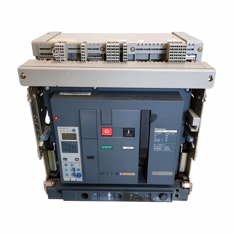
Product Overview
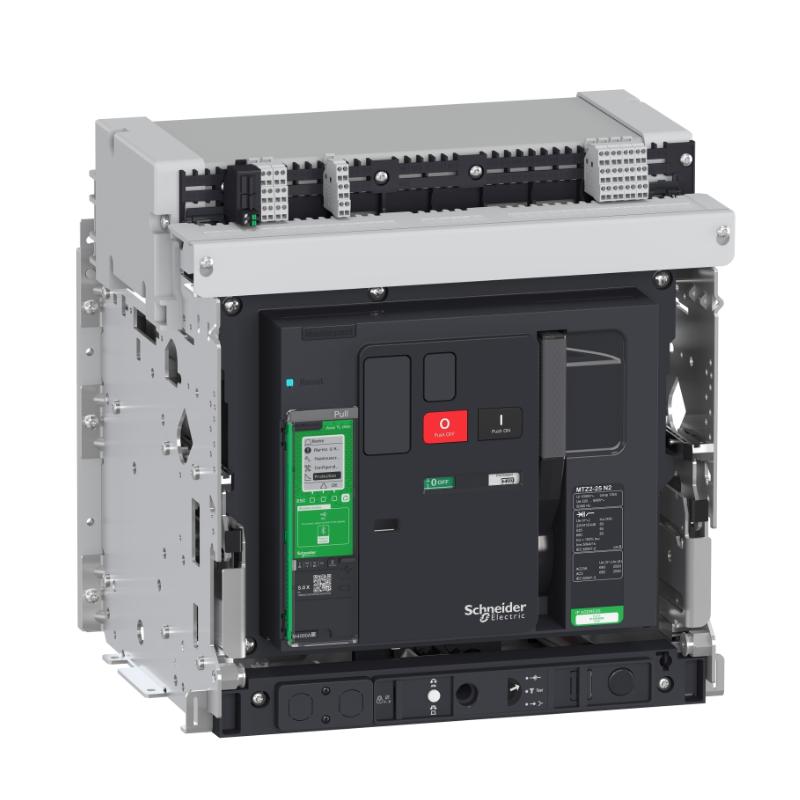
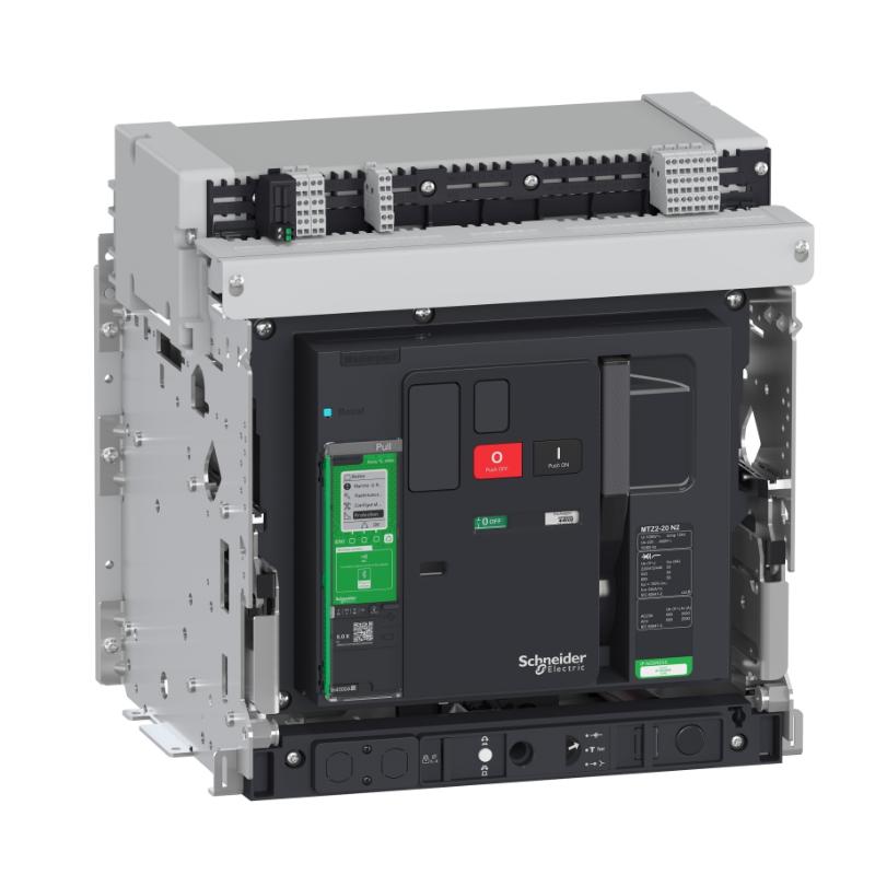
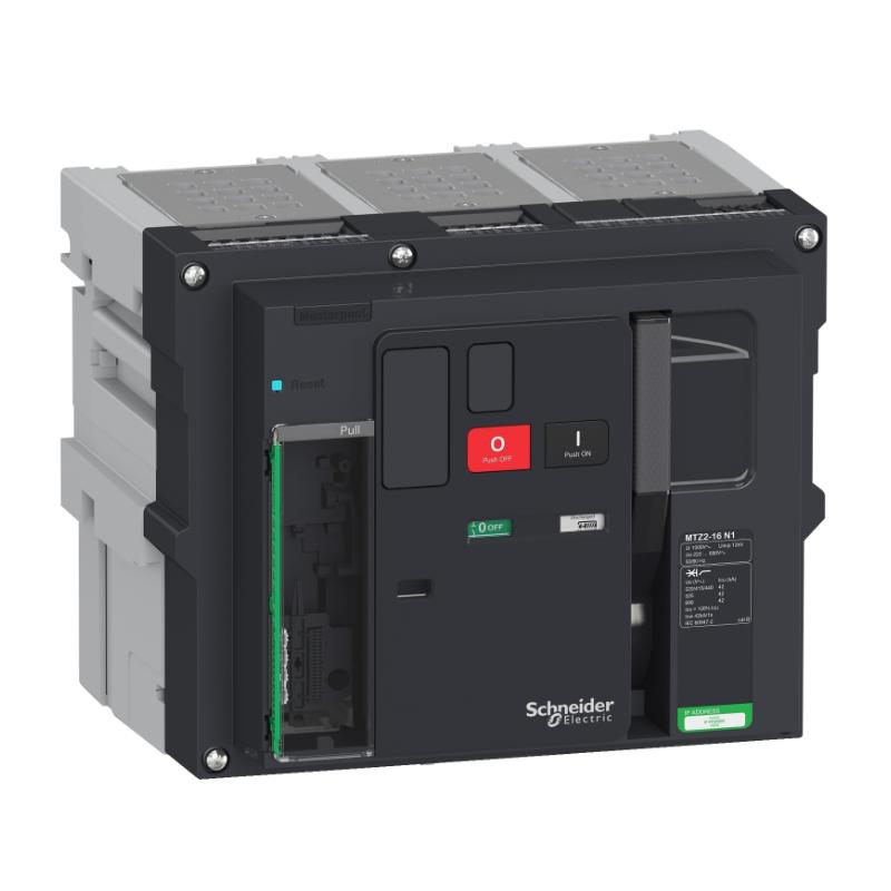
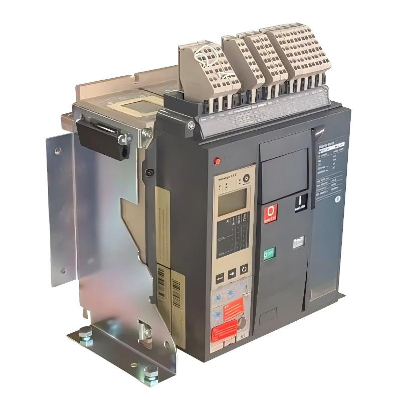
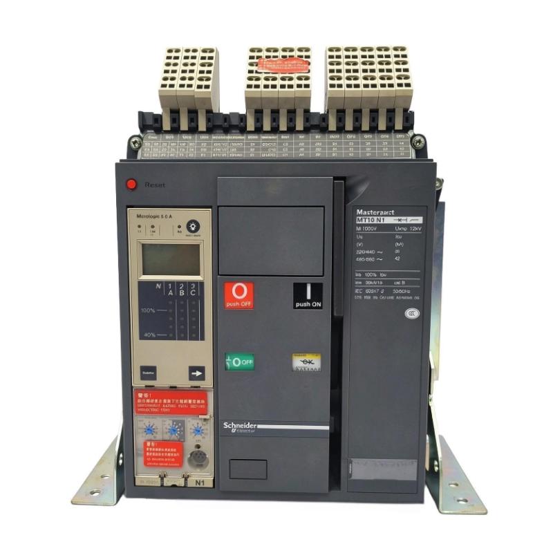
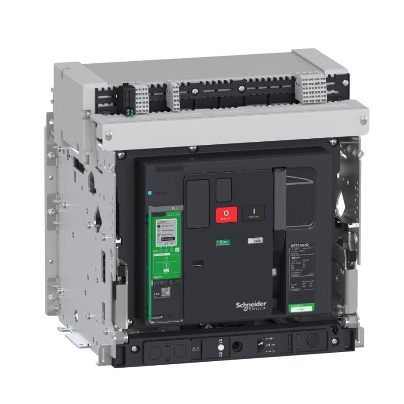
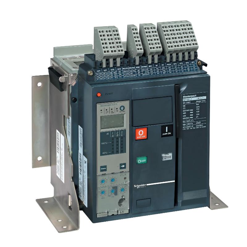
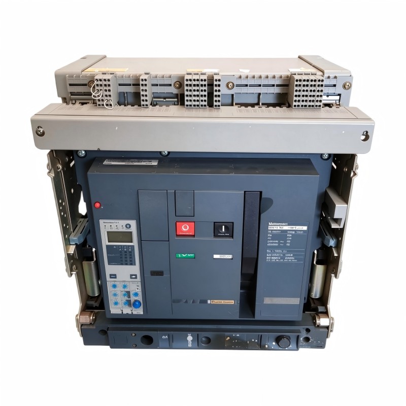
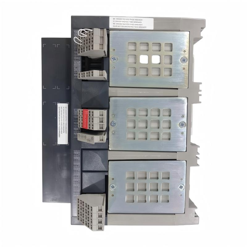
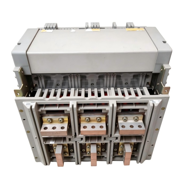
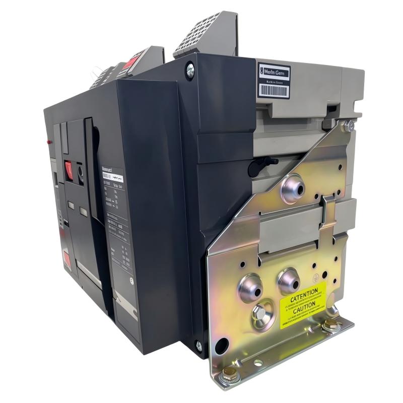
The Schneider Electric NW25N2 Circuit Breaker is a low-voltage air circuit breaker associated with the MasterPact NW series. Designed for industrial and commercial power distribution systems, this circuit breaker provides protection against electrical overloads and short-circuit faults while supporting the switching and isolation requirements of large electrical installations.
The MasterPact NW family is designed for demanding power distribution applications, including main incoming feeders, busbar systems, industrial switchboards, and large electrical distribution panels. These circuit breakers are commonly used where high current capacity, reliable interruption performance, and coordinated protection are important.
The NW25 designation identifies a 2500 A frame class. The exact electrical performance of an individual breaker depends on its complete configuration, including the interruption class, rated operating voltage, number of poles, trip unit, mounting arrangement, and installed accessories.
As part of a low-voltage protection system, the NW25N2 monitors current flowing through the protected circuit. When an abnormal electrical condition is detected by the configured protection system, the breaker can trip and interrupt the circuit. This helps protect downstream cables, electrical equipment, transformers, and other distribution components from damaging fault conditions.
The circuit breaker can also be incorporated into a broader power management system. Depending on the installed accessories, it may support remote operation, auxiliary status indication, electrical interlocking, and monitoring functions.
The supplied product dimensions are 352 × 537 × 297 mm, with a weight of 65 kg. These values correspond to the dimensional and weight information published for a fixed-mounted NW25 four-pole configuration. The exact mounting and pole arrangement should nevertheless be confirmed against the physical unit before installation.
Technical Specifications
| Parameter | Specification |
|---|---|
| Brand | Schneider Electric |
| Product Series | MasterPact NW |
| Model | NW25N2 |
| Product Type | Air Circuit Breaker (ACB) |
| Circuit Breaker Category | Low-Voltage Power Circuit Breaker |
| Frame Designation | NW25 |
| Frame Current Class | 2500 A |
| Mounting Configuration | Verify exact unit; supplied dimensions correspond to fixed-mounted configuration |
| Number of Poles | Verify product nameplate |
| Protection Function | Overload and short-circuit protection |
| Trip Unit | Depends on installed configuration |
| Operating Voltage | Verify nameplate and complete configuration |
| Short-Circuit Breaking Capacity | Depends on the exact N2 configuration and rated voltage |
| Dimensions | 352 × 537 × 297 mm |
| Weight | 65 kg |
| Typical Installation | Main switchboards and industrial power distribution systems |
| Manufacturer | Schneider Electric |
Important: NW25 is the 2500 A frame designation, not confirmation that every breaker has a 2500 A sensor or trip setting. Final electrical ratings must be checked against the breaker nameplate and the manufacturer’s documentation for the exact configuration.
Function and Working Principle
The NW25N2 is designed to protect electrical distribution circuits by detecting abnormal current conditions and interrupting the circuit when the configured protection thresholds are exceeded.
1. Overload Protection
An overload occurs when a circuit carries more current than its intended operating level for a sustained period. Overloads may result from excessive equipment demand, motor problems, incorrect load distribution, or changes in operating conditions.
The circuit breaker’s protection system monitors the current flowing through the protected conductors. When the overload condition meets the configured trip characteristics, the breaker initiates an opening operation.
This helps reduce the risk of excessive conductor heating and damage to connected electrical equipment.
2. Short-Circuit Protection
A short circuit can produce an extremely high current within a very short period. If not interrupted promptly, this fault may cause severe thermal and mechanical stress to busbars, cables, transformers, and connected equipment.
The circuit breaker is designed to interrupt fault currents within its specified breaking capacity. The exact interruption capability depends on the model configuration and operating voltage.
For this reason, the available short-circuit current at the installation point must be calculated and compared with the breaker’s rated interruption performance before commissioning.
3. Switching and Isolation
In addition to its protective functions, an air circuit breaker can be used for switching electrical distribution circuits.
Depending on the installed operating mechanism and accessories, the breaker may support manual or electrically operated opening and closing. This allows operators and control systems to manage the connection between the power source and the protected distribution circuit.
Isolation procedures must follow the applicable electrical safety requirements. A circuit breaker should not automatically be treated as a substitute for every required maintenance isolation device.
4. Protection Coordination
The NW25N2 can form part of a coordinated electrical protection system. In a typical distribution network, upstream and downstream circuit breakers are selected to operate in an appropriate sequence during fault conditions.
Correct coordination helps limit the section of the electrical system affected by a fault. This is particularly important in facilities where unnecessary interruption of the entire power distribution system could affect production or critical services.
Protection coordination requires engineering calculations using the actual breaker settings, fault levels, cable characteristics, and upstream and downstream protective devices.
5. Fault Interruption
When a trip condition is detected, the breaker mechanism separates its main contacts. The resulting electrical arc is managed by the breaker’s arc-control and interruption system.
The breaker is designed to extinguish the arc and interrupt current within its specified operating limits. This is an important function in high-current distribution systems, where fault energy can be substantial.
Role in Industrial Power Distribution Systems
The Schneider Electric NW25N2 is intended for use in larger low-voltage electrical distribution systems. It can serve as a protective and switching device in installations where high-current circuits require dependable interruption and operational control.
Main Incoming Circuit Protection
In industrial facilities, the main incoming circuit breaker connects the electrical supply to the main distribution switchboard. It provides a primary point of protection and switching for the downstream electrical installation.
A circuit breaker in the NW25 frame class may be considered for applications with substantial electrical demand, provided that the actual current and fault ratings are suitable.
Busbar Distribution Protection
Industrial switchboards use busbar systems to distribute electrical power to multiple outgoing feeders. A main or sectionalizing breaker can help protect and control these distribution sections.
The breaker’s frame class, pole configuration, connection arrangement, and short-circuit performance must be matched to the switchboard design.
Transformer Secondary Protection
A circuit breaker may be installed on the low-voltage side of a transformer to protect the downstream distribution network.
Selection requires consideration of transformer rated current, transformer impedance, prospective short-circuit current, protection coordination, and cable ratings.
Power Distribution Automation
In an automated electrical distribution system, circuit breakers may be integrated with monitoring devices, protection relays, PLCs, or supervisory control systems.
With suitable accessories, the breaker can provide status signals or receive remote operating commands. The exact communication and control functions depend on the installed equipment and system architecture.
Industrial Applications
1. Manufacturing Plants
Manufacturing facilities use large electrical distribution systems to supply production machinery, motor control centers, lighting, HVAC systems, and auxiliary equipment.
A high-current circuit breaker can serve as part of the main distribution protection arrangement. Its selection must consider the facility’s maximum demand, fault level, and protection coordination requirements.
2. Power Distribution Switchboards
Main and sectional distribution switchboards require protective devices capable of handling the electrical demands of the installation.
The MasterPact NW family is designed for low-voltage power distribution applications where high current ratings and configurable protection functions are required.
3. Data Centers
Data centers depend on stable electrical distribution for servers, cooling equipment, UPS systems, and auxiliary infrastructure.
Circuit breakers are used at different levels of the electrical distribution architecture to provide protection and switching. Their ratings and settings must be coordinated with upstream transformers, UPS equipment, busways, and downstream protective devices.
4. Commercial Buildings
Large commercial buildings may have electrical distribution systems serving elevators, air-conditioning equipment, lighting, pumps, and other major loads.
A suitably configured air circuit breaker can be used as a main or sectional protection device in the building’s low-voltage switchgear.
5. Infrastructure and Utility Installations
Water treatment facilities, transportation infrastructure, industrial utilities, and other large installations often require high-capacity low-voltage distribution equipment.
Air circuit breakers provide a means of protecting and controlling major distribution circuits in these environments.
6. Industrial Motor Control Centers
Motor control centers distribute electrical power to multiple motors and associated control equipment. A main circuit breaker can protect the incoming supply and support isolation of the distribution assembly.
The breaker must be coordinated with motor feeders, overload protection devices, contactors, and downstream circuit breakers.
Installation and System Integration
The installation of the NW25N2 requires careful attention to electrical ratings, mechanical mounting, connection arrangements, and protection settings.
1. Verify the Complete Breaker Configuration
Before installation, inspect the product nameplate and confirm:
- Complete model and catalog information.
- Rated operational voltage.
- Rated current and sensor configuration.
- Number of poles.
- Short-circuit breaking capacity.
- Trip unit type and protection settings.
- Fixed or drawout mounting arrangement.
- Installed electrical and mechanical accessories.
The NW25 frame designation alone is insufficient for confirming all electrical characteristics.
2. Check Panel Dimensions and Mounting
The supplied dimensions are 352 × 537 × 297 mm, and the supplied weight is 65 kg.
These values should be considered when planning the switchboard layout, mounting support, connection space, and handling arrangements.
The published dimensions correspond to a fixed-mounted four-pole NW25 configuration. If the actual breaker is a different pole or mounting arrangement, its dimensions may differ.
Because the breaker is a heavy electrical component, installation should use suitable lifting equipment and mechanical support. The switchboard structure must be designed to withstand the breaker’s weight and operating forces.
3. Verify Busbar and Cable Connections
The incoming and outgoing connections must be compatible with the breaker terminals and the switchboard busbar arrangement.
Check conductor cross-sections, terminal preparation, connection hardware, tightening torque, and clearances. These details should follow the manufacturer’s installation instructions.
Incorrect connections can lead to overheating, contact resistance, insulation damage, or mechanical problems.
4. Configure Protection Settings
The protection settings must be selected according to the electrical system design.
Relevant considerations include:
- Long-time overload protection.
- Short-time protection.
- Instantaneous short-circuit protection.
- Ground-fault protection, where supported.
- Coordination with upstream and downstream devices.
- Cable and busbar thermal limits.
Settings should be established by qualified electrical engineers using the actual system calculations and installed trip unit.
5. Integrate Auxiliary Contacts and Control Circuits
Depending on the installed accessories, auxiliary contacts may provide breaker open/closed status, trip indication, or other operational information.
Electrical operating mechanisms and interlocking devices may also be used in automated switchgear systems.
Before connecting control circuits, verify the accessory catalog numbers, control voltage, terminal assignments, and wiring diagrams.
6. Perform Commissioning Tests
Before energizing the switchboard, inspect the mechanical installation, electrical connections, insulation condition, grounding, and protective settings.
Commissioning may include mechanical operation checks, trip-unit verification, secondary injection testing, primary injection testing where required, and functional checks of auxiliary circuits.
Testing must be performed by qualified personnel using appropriate procedures and equipment.
Compatible System Components
The NW25N2 is normally installed as part of a larger low-voltage switchgear assembly.
| Component | Function | Integration Considerations |
|---|---|---|
| Low-voltage switchboard | Houses and distributes electrical power | Verify mechanical and electrical compatibility |
| Main busbar system | Distributes current through the switchboard | Confirm current rating, short-circuit withstand, and connection arrangement |
| Electronic trip unit | Provides configured protection functions | Verify exact trip unit and supported protection features |
| Auxiliary contacts | Provide breaker status signals | Confirm installed accessories and terminal assignments |
| Electrical operating mechanism | Supports remote opening and closing | Verify control voltage and mechanism compatibility |
| PLC | Coordinates electrical and process control | Use suitable interface and interlocking logic |
| Protection relay | Provides additional protection or monitoring | Confirm the protection scheme and coordination |
| Current transformers | Supply current measurement signals where required | Verify ratio, accuracy, and application |
| Energy meter | Monitors electrical consumption | Confirm measurement and communication requirements |
| UPS system | Provides backup electrical power | Coordinate protection and switching with the UPS design |
The components listed are examples of equipment that may be used in a complete distribution system. They are not necessarily included with the NW25N2 circuit breaker.
Alternative Models and Replacement Considerations
When replacing an existing MasterPact NW25N2, engineers should compare the complete electrical and mechanical configuration rather than relying on the frame designation alone.
| Alternative or Related Product | Replacement Considerations |
|---|---|
| Another MasterPact NW25 configuration | Check interruption class, trip unit, voltage, pole count, and mounting arrangement |
| MasterPact NW20 | Lower frame-current class; may not meet the original installation requirements |
| MasterPact NW32 | Higher frame-current class; requires a complete electrical and mechanical review |
| MasterPact NT series | Different breaker family and frame design; not automatically interchangeable |
| Current-generation Schneider Electric air circuit breaker | May be suitable for an upgrade, subject to switchboard and protection-system compatibility |
Before selecting a replacement, compare the following parameters:
- Rated operational voltage.
- Frame current and sensor rating.
- Rated service and ultimate short-circuit breaking capacities.
- Number of poles.
- Fixed or drawout mounting arrangement.
- Trip unit and protection functions.
- Busbar and terminal connection dimensions.
- Auxiliary contacts and electrical accessories.
- Mechanical interlocking and operating mechanism.
- Switchboard cutout, mounting, and clearance requirements.
A replacement breaker with the same frame current may still require changes to the switchboard, control wiring, protection settings, or busbar connections.
Key Advantages
High-Current Distribution Capability
The NW25 frame designation represents a 2500 A frame class, making this breaker family relevant to large low-voltage distribution applications.
Overload and Short-Circuit Protection
The breaker is designed to protect electrical circuits against abnormal current conditions within the limits of its configured protection system and rated interruption capability.
Industrial Switchgear Integration
The MasterPact NW family is designed for integration into industrial and commercial low-voltage switchgear assemblies.
Configurable Protection
The protection functions depend on the installed trip unit and configuration, allowing engineers to select suitable protection characteristics for the electrical system.
Switching and Operational Control
With the appropriate operating mechanism and accessories, the breaker can support manual or electrically controlled switching operations.
Support for Power Distribution Management
Suitable auxiliary contacts and monitoring equipment can help integrate the breaker into broader electrical monitoring and automation systems.
Technical FAQs
1. What is the Schneider Electric NW25N2?
The NW25N2 is a circuit breaker associated with Schneider Electric’s MasterPact NW low-voltage air circuit breaker family. It is intended for high-current electrical distribution and circuit protection applications.
2. What does NW25 mean?
NW25 identifies the 2500 A frame class within the MasterPact NW range. The actual sensor rating and protection settings depend on the installed configuration.
3. What is the rated current of the NW25N2?
The NW25 frame class is associated with 2500 A. However, the actual rated current or sensor rating of a specific breaker should be confirmed from its nameplate and installed trip-unit configuration.
4. What is the difference between an air circuit breaker and a molded case circuit breaker?
An air circuit breaker is generally used in larger low-voltage distribution systems and offers configurable protection and switching arrangements for high-current applications.
A molded case circuit breaker is typically more compact and is commonly used for smaller feeder and branch circuits. The appropriate choice depends on current rating, fault level, protection requirements, and installation design.
5. Can the NW25N2 be used as a main incoming breaker?
It may be used as a main incoming circuit breaker when its electrical ratings, interruption capability, protection settings, and mounting configuration are suitable for the installation.
6. Does the breaker support remote operation?
Remote operation depends on the installed electrical operating mechanism and accessories. The exact configuration should be checked before connecting the breaker to a PLC or supervisory control system.
7. What are the dimensions and weight of the NW25N2?
The supplied product dimensions are 352 × 537 × 297 mm, and the supplied weight is 65 kg. These values correspond to published dimensions and weight for a fixed-mounted four-pole NW25 configuration.
8. What should be checked before replacing the breaker?
Verify the complete model, rated voltage, current configuration, short-circuit breaking capacity, pole count, trip unit, mounting arrangement, accessories, and terminal connections.
9. Does the NW25N2 require periodic maintenance?
Yes. Maintenance should follow the manufacturer’s instructions and the facility’s electrical maintenance program. Inspections may include mechanical operation, contact condition, terminal connections, trip-unit functions, and auxiliary circuit operation.
10. Can the breaker be replaced by another NW25 model?
Not automatically. Different NW25 models may have different interruption ratings, trip units, mounting configurations, and accessories. A complete technical comparison is required before replacement.
Procurement and Maintenance Recommendations
The Schneider Electric NW25N2 is a large low-voltage circuit breaker intended for industrial and commercial power distribution systems. Because circuit breakers are safety-critical components, purchasing decisions should be based on complete technical identification rather than a general model-family description.
Before ordering, request clear photographs of the breaker nameplate, front panel, side labels, terminal connections, and installed accessories. Verify the rated current, voltage, interruption capacity, number of poles, trip unit, and mounting arrangement.
For used or refurbished equipment, check the mechanical operating mechanism, contact condition, insulation, trip-unit status, and available test records. Confirm whether the breaker has been inspected or functionally tested and establish the applicable warranty and return conditions.
During maintenance, follow the manufacturer’s service instructions and the facility’s electrical safety procedures. Keep connection surfaces clean, inspect terminals for signs of overheating, and verify the operation of protective and auxiliary functions at appropriate intervals.
For replacement projects, confirm the switchboard’s mechanical dimensions, busbar arrangement, electrical ratings, and control wiring before selecting another breaker. A model with a similar frame rating may still require engineering modifications.
Conclusion
The Schneider Electric NW25N2 Circuit Breaker is part of the MasterPact NW low-voltage air circuit breaker family and is intended for high-current power distribution and circuit protection applications. Its NW25 frame designation corresponds to a 2500 A frame class, while the actual operating and interruption ratings depend on the complete breaker configuration.
With supplied dimensions of 352 × 537 × 297 mm and a weight of 65 kg, this product is suitable for consideration in industrial switchboards and large electrical distribution installations where its verified electrical characteristics meet the system requirements.
For procurement, maintenance, and replacement work, checking the full nameplate information, trip-unit configuration, pole arrangement, and mounting details is essential to ensure electrical safety and compatibility.