

ProductPRODUCT
Featured products
Contact Us
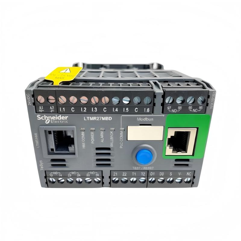
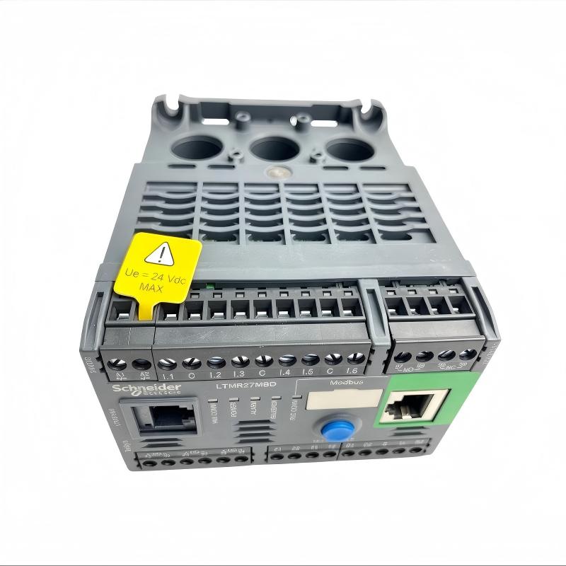
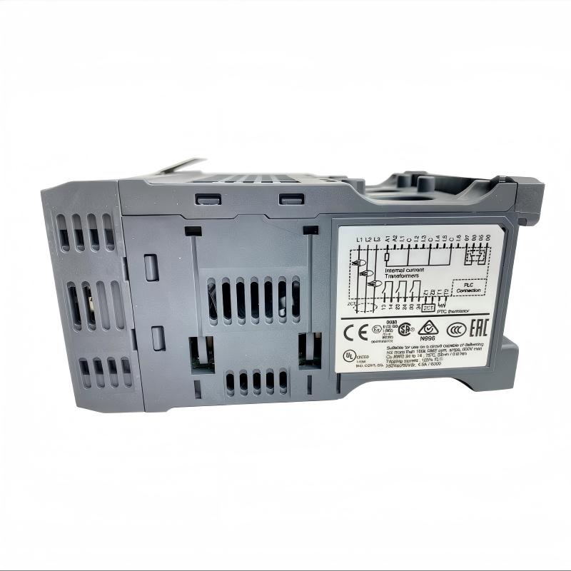
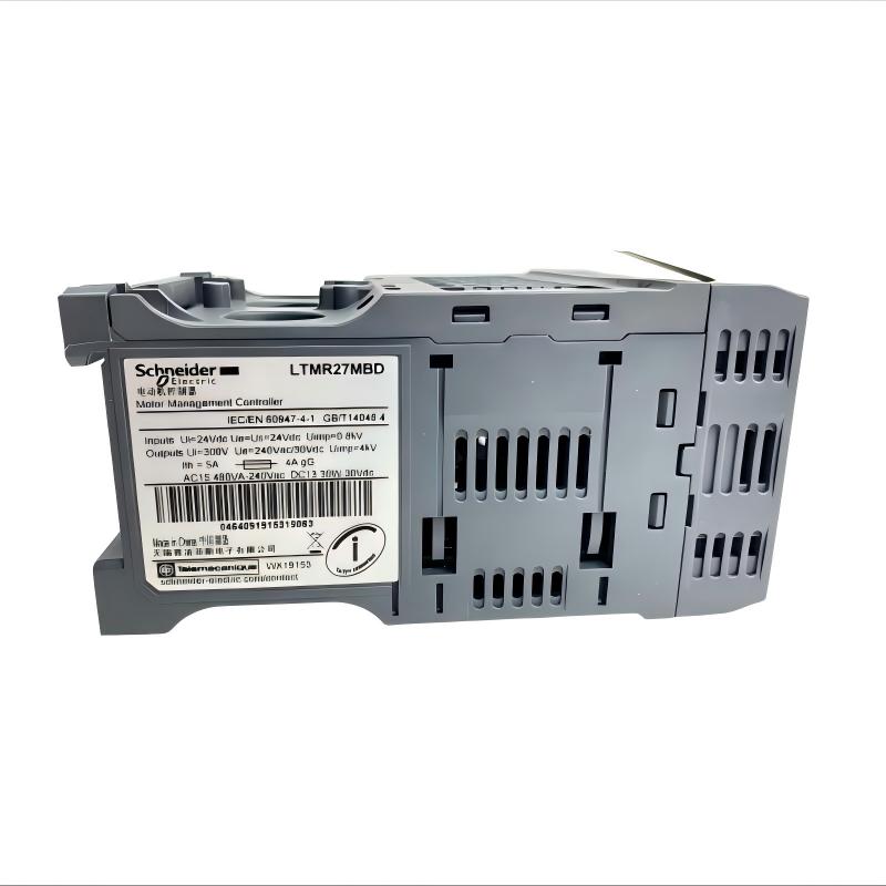
- Schneider
- LTMR27MBD
- Motor Controller
- France
- 91 x 61 x 122.5 mm
- 0.53 kg
- Xiamen, China
- New & In Stock
- T/T, PayPal, Western Union
- 1 Year
- 1-3 Working Days
- DHL, UPS, TNT, FedEx and EMS.
- 24-Hour Service
- COO
- 7
Our advantage

Global Logistics
We have a 10-year logistics and express cooperation agreement, so our products can be shipped to any place in the world.

Brand new and original
Our products are imported in bulk from the place of origin. Because of the cooperative relationship, our products are all original and 100% new.

24-hour service
We provide 7*24 hours service to our customers. We will be there whenever you need us.

Price advantage
All our products are priced very favorably because we have our own warehouse and supply.
| Company Information | |||
| [email protected] | |||
| Mobile | +8615980777398 | ||
| +8615980777398 | |||
| 15980777398 |
Product Overview
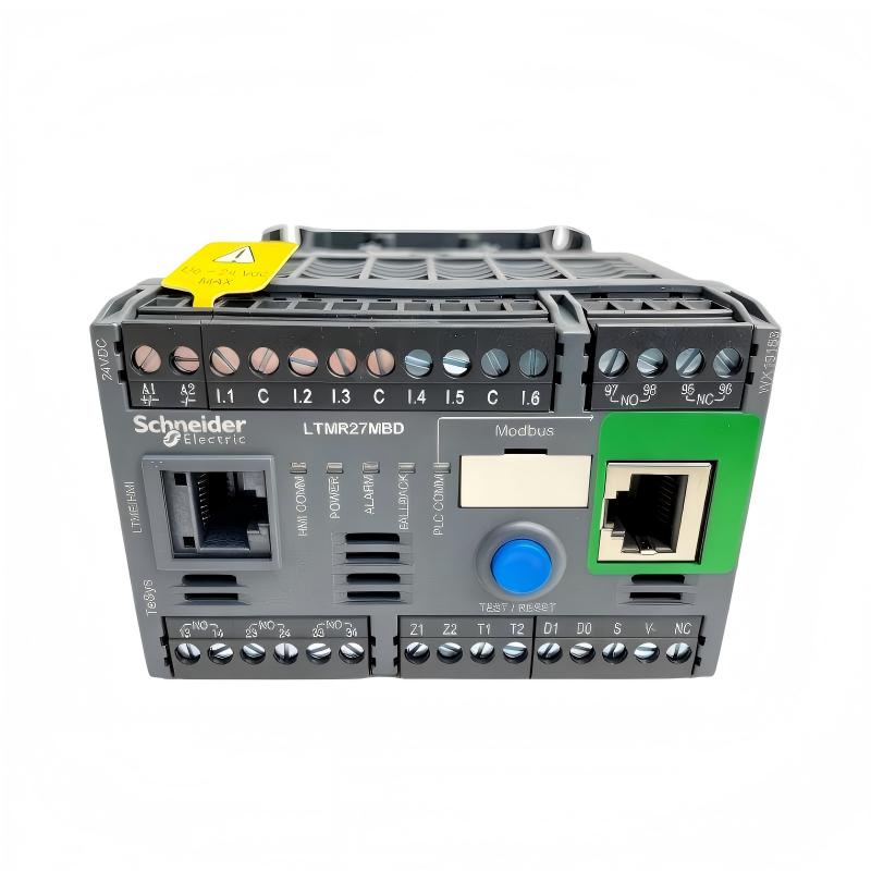
The Schneider Electric LTMR27MBD TeSys T Motor Controller is an intelligent motor management device designed for monitoring, controlling, and protecting industrial electric motors. It belongs to Schneider Electric’s TeSys T motor management system, which combines electrical measurements, motor protection functions, diagnostic information, and communication capabilities to support reliable industrial operation.
Unlike a conventional contactor, which primarily switches electrical power to a motor, the LTMR27MBD provides motor management functions that help automation systems monitor operating conditions and respond to detected faults. It measures motor current, evaluates protection conditions, communicates status information, and supports control strategies implemented through the controller’s inputs, outputs, and communication interface.
The LTMR27MBD operates from a 24 V DC control supply and supports a current measurement range of 1.35 to 27 A. It communicates using Modbus over a two-wire RS-485 interface and provides six logic inputs and three relay logic outputs. These features allow it to exchange motor status and control information with compatible PLCs, operator interfaces, and other automation equipment.
Typical functions include thermal overload protection, phase-loss detection, phase-imbalance monitoring, locked-rotor protection, and motor operating-time tracking. The device can help maintenance personnel identify abnormal operating conditions and investigate faults before they cause extended production interruptions.
The LTMR27MBD is intended for integration into a properly engineered motor starter or motor management assembly. It does not replace all the power-switching and short-circuit protection components required by a complete motor installation. A compatible contactor, suitable short-circuit protection, correctly rated wiring, and appropriate installation practices remain essential.
Technical Specifications
| Parameter | Specification |
|---|---|
| Brand | Schneider Electric |
| Product Family | TeSys T |
| Model | LTMR27MBD |
| Product Type | Motor Management Controller |
| Primary Function | Motor monitoring, control, and protection |
| Control Supply Voltage | 24 V DC |
| Supply Voltage Limits | 20.4–26.24 V DC |
| Current Measurement Range | 1.35–27 A |
| Communication Protocol | Modbus RTU |
| Communication Interface | Two-wire RS-485 |
| Communication Connectors | RJ45 and terminal block, according to configuration |
| Logic Inputs | 6 |
| Relay Logic Outputs | 3 |
| Fault Signalling Output | 1 normally open and 1 normally closed contact arrangement |
| Rated Insulation Voltage | 690 V |
| Protection Functions | Thermal overload, phase loss, phase imbalance, locked rotor, and related motor faults |
| Mounting | Panel or DIN-rail installation as supported by the product arrangement |
| Dimensions Provided | 91 × 61 × 122.5 mm |
| Weight Provided | 0.53 kg |
| Product Lifecycle | Discontinuation and end-of-service dates published by Schneider Electric; verify regional status |
| Typical Application | Industrial motor management and protection systems |
Note: Confirm the exact hardware, wiring arrangement, and applicable product documentation before installation. The dimensions and weight above are the supplied listing values.
Function and Working Principle
The LTMR27MBD operates as the monitoring and control component of a motor management system. It receives electrical measurements and control signals, evaluates them against configured parameters, and makes motor status and fault information available to the wider automation system.
1. Motor Current Measurement
The controller supports a current measurement range of 1.35–27 A. Current measurement helps establish how a motor is operating under its actual load.
When a motor draws more current than expected, the condition may indicate excessive mechanical load, a process obstruction, incorrect operating conditions, or an electrical problem. The controller can use measured current and configured protection settings to detect certain abnormal conditions.
Correct application setup is important. The motor’s nameplate current and operating characteristics should be used when selecting protection settings rather than relying only on the maximum current range of the controller.
2. Thermal Overload Protection
Motor windings generate heat during operation. Excessive current, frequent starting, poor cooling, and prolonged mechanical overload can raise winding temperature and shorten motor life.
The LTMR27MBD provides thermal overload protection functions that evaluate motor operating conditions and help prevent sustained overload from damaging the motor.
The protection settings must reflect the motor’s rated current, starting characteristics, duty cycle, and operating environment. The controller should be commissioned according to the manufacturer’s instructions and the requirements of the connected motor.
3. Phase-Loss and Phase-Imbalance Detection
Three-phase motors depend on an appropriate supply arrangement. A missing phase or significant phase imbalance can produce abnormal currents and excessive motor heating.
The controller supports phase-related fault detection to help identify these conditions. When a fault is detected, the configured control system can take appropriate action, such as stopping the motor and reporting the fault to a PLC or operator interface.
The actual response depends on the configured protection settings and the motor-control circuit.
4. Locked-Rotor and Abnormal Load Protection
A motor may draw excessive current if its shaft is mechanically blocked or the driven equipment cannot move as expected. This can happen because of a jammed conveyor, a blocked pump, a seized mechanism, or a mechanical failure.
The LTMR27MBD supports locked-rotor and related motor protection functions. By detecting abnormal operating conditions, it can help prevent prolonged fault operation and support faster troubleshooting.
Protection thresholds and delay settings must be chosen according to the equipment’s normal starting and running characteristics.
5. Motor Operating Data and Diagnostics
The TeSys T system provides diagnostic and operating information that can support maintenance planning. Depending on the configured functions, this information may include operating hours, starting current, fault history, and details associated with detected trips.
Such information helps maintenance teams distinguish between recurring electrical problems, excessive load, and process-related faults. It can also provide a useful record when investigating repeated shutdowns.
6. Communication and Control
The LTMR27MBD communicates using Modbus over RS-485. Through a compatible network configuration, a PLC or supervisory system can exchange supported operating information and control commands with the controller.
The communication settings, addressing, wiring, and control logic must be configured consistently across the system. Communication availability does not eliminate the need for correctly designed hardwired control circuits or application-specific safety measures.
Role in Industrial Control Systems
The LTMR27MBD can serve as the motor management layer within an industrial automation system. It connects motor operating information with the control and monitoring functions used by maintenance staff, machine operators, and automation engineers.
PLC Integration
A programmable logic controller can coordinate motor operation with sensors, actuators, production sequences, and interlocks. The LTMR27MBD provides a Modbus interface through which a compatible PLC can exchange supported data.
The PLC may use motor status and fault information to determine whether a production sequence can continue, whether an alarm should be generated, or whether a controlled shutdown is required.
During integration, engineers should confirm the Modbus address, communication speed, register mapping, and control strategy. The controller and PLC must use matching communication parameters.
HMI and SCADA Monitoring
An HMI or SCADA system can display motor status, current-related information, fault conditions, and operating history when the necessary data is available through the configured controller and PLC interface.
Operators can use this information to identify abnormal conditions and determine whether maintenance attention is required. The controller’s diagnostic capabilities can reduce reliance on basic run and stop indicators alone.
The display design should distinguish between normal operating messages, warnings, and trip conditions so that operators can respond appropriately.
Motor Starter Coordination
The LTMR27MBD is designed to work within a motor management arrangement that includes appropriate power-switching and protective components. A contactor provides the power-switching function, while suitable short-circuit protection protects the electrical installation.
The motor controller contributes measurement, monitoring, and protection functions. These components must be coordinated so that fault detection produces the intended response in the motor starter circuit.
Maintenance and Troubleshooting
Motor operating information and recorded fault data can help maintenance personnel investigate recurring trips. For example, repeated overload events may indicate a process load problem, unsuitable motor sizing, or mechanical resistance.
By reviewing controller diagnostics alongside the actual machine conditions, engineers can identify potential causes more efficiently and reduce unnecessary component replacement.
Industrial Applications
The LTMR27MBD is suitable for industrial motor management applications where current measurement, motor protection, and Modbus communication are required.
1. Conveyor Systems
Conveyor motors operate under changing loads as products enter, move through, and leave a production line. Mechanical obstructions or excessive product accumulation can increase motor loading.
The LTMR27MBD can monitor motor operating conditions and provide fault information to the control system. This helps operators identify abnormal loads and coordinate shutdown or alarm responses.
2. Pumping Equipment
Industrial pumps are used in water treatment, manufacturing, cooling systems, and process-fluid handling. Pump motors can experience overloads due to mechanical problems, blocked components, or unsuitable process conditions.
Motor management functions can help detect electrical conditions associated with these problems. Correct protection settings should be selected according to the motor and the pump’s normal operating profile.
3. Fans and Ventilation Systems
Industrial fans support ventilation, cooling, and air movement. Motor faults can affect equipment availability and the environmental conditions of a production area.
The LTMR27MBD can provide current monitoring and fault information for compatible fan motor circuits. Integration with the plant’s control system helps maintenance personnel identify trips and determine whether inspection is necessary.
4. Compressors and Auxiliary Machinery
Industrial compressor packages and auxiliary machines rely on electric motors to drive pumps, fans, and other equipment. Unexpected motor trips can interrupt production or reduce system availability.
The controller’s monitoring and protection functions can help detect abnormal motor conditions and provide information for troubleshooting. Application-specific protection requirements should be checked carefully, particularly for critical process equipment.
5. Manufacturing and Assembly Equipment
Production machinery often contains multiple motors that operate in a coordinated sequence. Monitoring motor status and fault conditions helps the PLC determine whether each part of the process is operating normally.
The LTMR27MBD can support this approach when its current range, protection functions, and communication capabilities match the application requirements.
6. Water Treatment and Process Plants
Pumps, mixers, and auxiliary motors are common in water treatment and process facilities. Electrical overloads, phase faults, and mechanical obstructions can affect operating continuity.
A motor management controller can provide an additional layer of monitoring and protection, helping maintenance teams identify faults and manage equipment availability.
Installation and System Integration
Correct installation is essential for reliable operation and accurate motor protection.
1. Verify the Control Supply
The LTMR27MBD uses a nominal 24 V DC control supply, with a published operating range of 20.4–26.24 V DC.
Confirm the power supply polarity, voltage, current capacity, and wiring before energizing the controller. An unstable or incorrectly connected control supply can cause communication problems or prevent normal operation.
2. Confirm the Motor Current Range
The supported measurement range is 1.35–27 A. Confirm that the motor and application fall within the controller’s specified operating range.
Set the protection parameters according to the motor nameplate and application requirements. Do not assume that a controller with a 27 A upper limit is appropriate for every motor below that value without checking the complete protection and installation requirements.
3. Install the Required Power Circuit Components
The LTMR27MBD is part of a motor management system rather than a standalone power-switching device. The complete assembly must include the appropriate contactor, short-circuit protection, and motor wiring.
Select protective devices according to the manufacturer’s coordination recommendations and applicable electrical standards. Ensure that the controller, contactor, and protection devices are compatible with the intended motor circuit.
4. Configure Modbus Communication
For Modbus RTU communication, configure the network address, transmission speed, and other required communication parameters.
Use the correct RS-485 wiring arrangement and follow the manufacturer’s grounding, shielding, and termination recommendations. Incorrect network configuration may result in intermittent communication, missing data, or failed commands.
Where the installation uses the RJ45 or terminal-block interface, verify the exact connector assignment and supported wiring method before connecting the network.
5. Configure Protection and Control Parameters
Set the motor current reference and the relevant protection functions according to the application. These may include overload, phase-related faults, locked-rotor protection, and other supported monitoring functions.
Confirm how each detected fault affects the motor-control circuit. A controller’s fault detection must be coordinated with the contactor and PLC logic so that the intended shutdown and alarm response occurs.
6. Test the Installation
After wiring and configuration, check the control supply, communication status, input signals, relay outputs, and motor protection settings.
Test the intended motor-start and motor-stop sequence under controlled conditions. Verify that fault conditions generate the correct response and that status information is correctly displayed by the PLC or HMI.
Document the final configuration to support future maintenance and troubleshooting.
Compatible System Components
The LTMR27MBD is normally installed as part of a wider motor management system. The following components may be used depending on the application and control architecture.
| Component | Function | Integration Considerations |
|---|---|---|
| Three-phase AC motor | Drives the connected mechanical load | Confirm rated current, starting characteristics, and duty cycle |
| Contactor | Switches motor power | Select a compatible contactor and verify the required control circuit |
| Short-circuit protective device | Protects against short-circuit faults | Select according to the manufacturer’s coordination requirements |
| 24 V DC power supply | Powers the controller | Maintain the specified voltage range and sufficient current capacity |
| PLC | Coordinates machine operation | Configure Modbus communication or the required control signals |
| HMI | Displays motor status and alarms | Use supported controller data and clearly defined alarm logic |
| SCADA system | Provides supervisory monitoring | Confirm PLC or gateway support for the required data exchange |
| RS-485 communication cable | Carries Modbus RTU data | Follow wiring, shielding, and network-topology recommendations |
| Motor temperature sensor | Provides additional motor thermal information where supported | Verify sensor type and connection requirements |
| Current and ground-fault sensing accessories | Support applicable measurement functions | Confirm compatibility with the intended TeSys T configuration |
The listed components are examples of a complete installation and are not necessarily included with the LTMR27MBD.
Alternative Models and Replacement Considerations
Schneider Electric has published replacement recommendations for the LTMR27MBD within its TeSys Tera motor management range. The correct replacement depends on the required current measurement range, control supply, communication interface, and application requirements.
| Alternative or Related Model | Considerations |
|---|---|
| Schneider Electric LTMTMBD | TeSys Tera motor management main unit with Modbus and 24 V DC supply; select the appropriate compatible sensor |
| Schneider Electric LTMTCTV25UT | A TeSys Tera current sensor option with a 2.5–25 A range, subject to the replacement configuration specified by the manufacturer |
| Schneider Electric LTMTCTV3UT | A TeSys Tera current sensor option with a 0.3–3 A range; suitable only when the motor’s requirements match |
| Schneider Electric LTMR27MFM | Related TeSys T controller using a 100–240 V AC control supply; not a direct electrical substitute for the 24 V DC LTMR27MBD |
| Schneider Electric LTMR27EBD | Related TeSys T controller with Ethernet-based communication options; network and control compatibility must be evaluated |
Before choosing a replacement, verify:
- Required motor current range.
- Control supply voltage.
- Communication protocol and network architecture.
- Number and type of inputs and outputs.
- Protection functions and parameter settings.
- Contactor and short-circuit protection coordination.
- Mounting and wiring requirements.
- PLC register mapping and HMI integration.
- Availability of compatible sensors and accessories.
A replacement may require changes to the control panel, wiring, PLC program, communication configuration, and commissioning procedure. Do not assume that a newer product is a plug-in replacement without confirming the manufacturer’s approved configuration.
Key Advantages
Comprehensive Motor Monitoring
The LTMR27MBD provides current measurement and operating information that help engineers understand motor conditions and investigate abnormal events.
Multiple Motor Protection Functions
Supported protection functions include thermal overload and phase-related fault detection, helping reduce the risk of prolonged operation under damaging conditions.
Modbus RTU Communication
The RS-485 Modbus interface supports data exchange with compatible PLCs and other automation equipment, enabling centralized monitoring and control.
Six Logic Inputs and Three Relay Logic Outputs
The available I/O supports connection to control signals and relay-based functions within an appropriately designed motor-control circuit.
Diagnostic Information
Fault and operating records can help maintenance personnel identify recurring problems, review motor operating conditions, and plan inspections.
Integration with TeSys T
As part of the TeSys T motor management system, the controller can be incorporated into a coordinated arrangement of motor protection, control, and monitoring components.
Support for Industrial Automation
The controller can help integrate motor management into automated production systems, where reliable motor status information is important for equipment availability and troubleshooting.
Technical FAQs
1. What is the Schneider Electric LTMR27MBD?
The LTMR27MBD is a TeSys T motor management controller designed for motor monitoring, control, and protection. It uses a 24 V DC control supply and supports Modbus RTU communication.
2. What is the current range of the LTMR27MBD?
Its published current measurement range is 1.35–27 A. The connected motor’s rated current and operating characteristics should be checked before selecting protection settings.
3. What communication protocol does it support?
The LTMR27MBD supports Modbus over a two-wire RS-485 interface. The network address, communication speed, and wiring must be configured correctly for reliable data exchange.
4. How many inputs and outputs does it have?
The controller provides six logic inputs and three relay logic outputs. It also provides a fault-signalling relay contact arrangement, as specified in the product documentation.
5. Does the LTMR27MBD switch motor power directly?
It is a motor management controller, not a standalone motor power contactor. A complete motor starter requires suitable power-switching and short-circuit protective components.
6. What protection functions are available?
The product supports motor protection functions such as thermal overload, phase loss, phase imbalance, and locked-rotor detection. The actual response depends on the selected settings and the design of the motor-control circuit.
7. Can it communicate with a PLC?
Yes. A compatible PLC can exchange supported information through the Modbus RTU interface. Network settings and data mapping must be configured according to the system design.
8. Is the LTMR27MBD still available?
Schneider Electric has published a discontinuation date of September 30, 2026, and an end-of-service date of January 31, 2027, on its product information. As these dates have passed or are approaching according to the published lifecycle schedule, confirm current availability and service status with Schneider Electric or an authorized distributor.
9. Can it be replaced with an LTMR27MFM?
Not without checking the control supply requirements. The LTMR27MFM uses a 100–240 V AC control supply, while the LTMR27MBD uses 24 V DC. The supply and control-panel design must be compatible before substitution.
10. What should be checked when buying a used unit?
Verify the complete model number, nameplate, physical condition, terminals, communication interface, and available test results. Confirm the unit’s service history where possible and check whether compatible accessories and documentation are available.
Procurement and Maintenance Recommendations
When sourcing the Schneider Electric LTMR27MBD, begin by confirming the exact model and its role in the existing motor management system. Check the 24 V DC control supply, 1.35–27 A measurement range, Modbus RTU interface, and available I/O against the installed configuration.
For new-old-stock, used, or refurbished units, request clear nameplate photographs and inspect the terminal condition and housing. Where the device is used in a critical process, request suitable functional testing and confirm the seller’s warranty and return conditions.
During maintenance, review fault records, inspect wiring and terminals, and confirm that the control supply remains within its specified range. Check the communication network for loose connections, incorrect addressing, and intermittent data exchange.
Protection settings should be documented and reviewed whenever the motor, driven equipment, or operating conditions change. Any modification to the motor starter or controller configuration should be followed by appropriate commissioning tests.
Because the LTMR27MBD is approaching or has passed its published discontinuation milestone, maintenance teams should also evaluate the availability of replacement units and compatible accessories. If a TeSys Tera replacement is considered, review the complete system configuration rather than replacing the controller alone.
Conclusion
The Schneider Electric LTMR27MBD TeSys T Motor Controller is an intelligent motor management device designed for industrial monitoring, control, and protection. Its 24 V DC supply, 1.35–27 A current measurement range, Modbus RTU communication, six logic inputs, and three relay logic outputs support integration into PLC-based motor management systems.
By providing motor measurements, protection functions, and diagnostic information, the LTMR27MBD can help improve fault visibility and support industrial maintenance activities. Correct selection, configuration, and integration with contactors and short-circuit protective devices are essential for safe operation.
For replacement and procurement projects, verify the exact model, current range, control supply, communication requirements, and lifecycle status before installation.