
NewsNEWCENTER
Featured products
Contact Us
Schneider Electric 140ATI03000 Installation Guide: Modicon Quantum 8-Channel Thermocouple Input Module
2026-10-28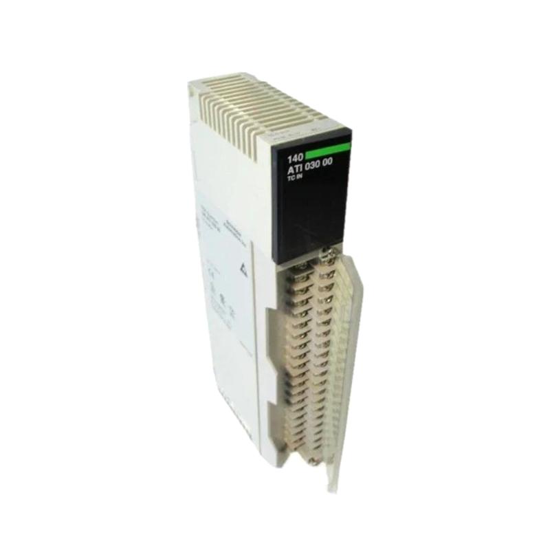
The Schneider Electric 140ATI03000 is an eight-channel analog input module for the Modicon Quantum automation platform. Designed primarily for thermocouple temperature measurement, it converts low-level sensor signals into digital values that a PLC can use for process monitoring, temperature control, alarms, and industrial automation applications.
Correct installation of the Schneider 140ATI03000 requires attention to rack compatibility, thermocouple type selection, sensor polarity, extension-wire materials, cold junction compensation, channel configuration, and PLC data scaling. Because thermocouples generate small electrical signals, wiring quality and temperature reference compensation are especially important for achieving reliable measurements.
Table of Contents
- 1. Product Overview
- 2. Technical Specifications
- 3. Installation Preparation
- 4. Rack Installation and Mounting
- 5. Thermocouple Wiring and Sensor Connections
- 6. PLC Configuration and Channel Setup
- 7. Cold Junction Compensation
- 8. Commissioning and Functional Testing
- 9. Industrial Applications and System Integration
- 10. Maintenance and Troubleshooting
- 11. Frequently Asked Questions
- 12. Technical Summary
1. Product Overview
The 140ATI03000 belongs to Schneider Electric’s Modicon Quantum family of programmable logic controller modules. It is designed to receive low-level analog signals from thermocouples and provide temperature measurement data to the PLC processor.
The module supports eight thermocouple input channels and accepts several common thermocouple types, including J, K, E, T, R, and S. These sensor types are used across a broad range of industrial temperature applications, from general process heating to high-temperature furnace monitoring.
Thermocouples operate by producing a small voltage related to the temperature difference between the measuring junction and the reference junction. The 140ATI03000 processes the sensor signal and uses cold junction compensation to calculate a temperature value for the configured sensor type.
Key product characteristics
- Eight thermocouple input channels.
- Support for thermocouple types J, K, E, T, R, and S.
- 16-bit analog input resolution according to the product datasheet.
- Internal cold junction compensation, with external compensation options for supported sensor types.
- 50/60 Hz notch filtering and a low-pass input filter.
- Channel and bus isolation specified in the product documentation.
- Integration with compatible Modicon Quantum PLC systems.
Product lifecycle note: Schneider Electric lists the 140ATI03000 as discontinued. The published end-of-service date is December 31, 2030, although availability and service arrangements should be confirmed for the relevant market. For existing installations, verify the exact catalog reference and investigate the manufacturer’s recommended migration options before planning a replacement.
2. Technical Specifications
| Parameter | Specification |
|---|---|
| Manufacturer | Schneider Electric |
| Product family | Modicon Quantum |
| Model | 140ATI03000 |
| Product type | Analog thermocouple input module |
| Number of input channels | 8 |
| Supported thermocouple types | J, K, E, T, R, S |
| Input resolution | 16 bits |
| Input impedance | Greater than 1 MΩ |
| Addressing requirement | 10 input words |
| Input filtering | 50/60 Hz notch filter and approximately 20 Hz low-pass filter |
| Typical update time | Approximately 1000 ms |
| Internal cold junction compensation | Supported; specified operating range 0–60°C |
| Backplane current requirement | 280 mA |
| Power dissipation | Approximately 1.5 W |
| Net weight | Approximately 0.3 kg |
| Channel-to-bus isolation | 1780 V AC for 60 seconds; 2500 V DC for 60 seconds, under specified test conditions |
These values provide a general technical reference. Always verify the installed hardware revision and applicable module documentation before finalizing rack power calculations, wiring, configuration, or commissioning procedures.
3. Installation Preparation
Before installing the 140ATI03000, verify the PLC hardware, sensor types, cabinet conditions, and configuration requirements. Good preparation helps prevent inaccurate temperature readings and unnecessary commissioning delays.
3.1 Verify the module reference
Check the complete catalog number printed on the module label. Ensure that the hardware matches the planned Modicon Quantum configuration and that the correct installation documentation is available.
3.2 Check rack capacity
Confirm that the rack power supply can support the module’s backplane current requirement of approximately 280 mA, in addition to the demands of all other installed modules. Review the rack’s thermal conditions and ensure that the cabinet provides adequate ventilation.
3.3 Identify each thermocouple
Prepare a channel schedule listing the sensor tag, thermocouple type, measurement location, expected temperature range, and PLC variable. Confirm whether each sensor uses type J, K, E, T, R, or S wire.
Do not select a thermocouple type solely from the expected process temperature. The sensor itself, extension cable, connector materials, and channel configuration must be compatible.
3.4 Prepare the necessary tools
- Approved electrical test equipment suitable for low-level thermocouple signals.
- Correct thermocouple extension wire and compatible connectors.
- Terminal tools specified for the applicable hardware.
- Sensor and channel identification labels.
- PLC programming software and the existing project backup.
- Approved temperature reference or simulator, where required for commissioning.
4. Rack Installation and Mounting
Step 1: Prepare the control cabinet
Ensure that the cabinet is clean, dry, and suitable for the installation environment. Check for excessive heat, vibration, contamination, or other conditions that may affect electronic modules and low-level sensor wiring.
Step 2: Isolate power
Follow the plant’s lockout/tagout procedures and the applicable Modicon Quantum hardware instructions before installing or removing the module. Confirm the equipment is in a safe state and use appropriate electrostatic discharge precautions when handling the module.
Step 3: Inspect the rack connector
Inspect the module connector and rack slot for visible damage, contamination, or bent contacts. Do not force the module into position if the mechanical alignment is incorrect.
Step 4: Install the module
Insert the 140ATI03000 into the designated compatible rack position and secure it according to the system’s installation instructions. Check that the module is fully seated and mechanically secure.
Step 5: Confirm the terminal block
Verify the compatible field wiring terminal block and any required accessories using the module documentation. Do not assume that a terminal block or wiring arrangement from a different Quantum analog input module is interchangeable.
5. Thermocouple Wiring and Sensor Connections
Thermocouples produce low-level millivolt signals, so wiring errors that may be insignificant in other applications can create noticeable temperature measurement errors. Use the sensor manufacturer’s wiring guidance together with the Schneider Electric connection diagram for the installed module.
5.1 Use the correct thermocouple wire
Use thermocouple extension or compensating cable appropriate for the sensor type. For example, type K extension cable must be suitable for type K thermocouples. Using ordinary copper wire or an incompatible extension cable can introduce additional junctions and measurement errors.
5.2 Verify polarity
Identify the positive and negative conductors using the cable manufacturer’s markings and the approved wiring diagram. Confirm polarity at both the field sensor and the module terminal block.
Reversed polarity can cause incorrect readings and may cause the displayed temperature to move in the wrong direction when the process temperature changes. Do not rely on conductor color alone where local color conventions or cable standards may differ.
5.3 Separate low-level signals from power wiring
- Route thermocouple cables away from motor power cables, contactors, variable-speed drives, and high-current conductors where practical.
- Use suitable shielding and grounding arrangements specified by the sensor and control-system documentation.
- Avoid unnecessary cable splices and incompatible connector materials.
- Keep terminal connections secure and protect conductors against mechanical damage.
- Maintain clear identification for each sensor and channel.
5.4 Check the sensor circuit
Inspect the thermocouple, extension cable, junction boxes, and terminal connections for breaks, corrosion, loose conductors, and signs of overheating. An open sensor circuit may produce a fault indication or an abnormal value, depending on the configured channel and diagnostic behavior.
When testing continuity, follow the approved procedure and disconnect the circuit as required. Do not use a test method that could damage the low-level input circuitry.
6. PLC Configuration and Channel Setup
Once the module is installed and the field wiring has been checked, configure the 140ATI03000 in the supported Modicon Quantum programming environment. The precise steps depend on the controller, software version, and existing project configuration.
6.1 Configure the rack and module
Verify the module’s rack and slot assignment in the PLC hardware configuration. Confirm that the project identifies the correct analog thermocouple input module and reserves the required input data.
The module’s addressing requirement is documented as 10 input words. Confirm how those words are assigned in the specific application and avoid copying addresses from another rack or project without verification.
6.2 Select the thermocouple type for each channel
Configure every channel for the sensor actually connected to it. Supported types include J, K, E, T, R, and S. Each type has a different temperature-to-voltage relationship, so an incorrect selection can result in an inaccurate temperature value even when the wiring is correct.
For example, a type K thermocouple connected to a channel configured for type J will not produce a reliable temperature measurement across the intended operating range.
6.3 Verify the temperature units and data format
Check how the module represents temperature data and whether the PLC application expects degrees Celsius, degrees Fahrenheit, or another documented format. Confirm any scaling, offset correction, and conversion logic in the application program.
Do not apply generic raw-count scaling until the actual data format and module configuration have been verified.
6.4 Configure alarms and operating limits
Establish appropriate high-temperature, low-temperature, and sensor-fault alarms for the application. Use suitable process limits and ensure that alarm behavior has been tested during commissioning.
For safety-related functions, follow the plant’s approved functional safety design. A standard analog input value should not be assumed to provide a certified safety function unless the entire system has been specifically designed and validated for that purpose.
7. Cold Junction Compensation
Cold junction compensation (CJC) is essential for accurate thermocouple measurement. A thermocouple produces a voltage based on the temperature difference between its measuring junction and reference junction. The reference junction temperature must therefore be accounted for when calculating the actual measurement temperature.
7.1 Internal compensation
The 140ATI03000 supports internal cold junction compensation. In the normal installation arrangement, the module’s internal reference measurement is used as part of the temperature calculation.
Ensure that the module and terminal area operate within the documented temperature conditions. Uneven heating, external heat sources, or poor cabinet temperature management may affect measurement performance.
7.2 External compensation options
The module documentation also describes the use of remote cold junction compensation for supported thermocouple types J, K, and T. This arrangement must follow the manufacturer’s approved wiring and configuration instructions.
Do not assume that external compensation is supported in the same way for every thermocouple type. Verify the exact sensor type, terminal arrangement, and configuration requirements before implementing an alternative CJC method.
7.3 Common cold junction compensation problems
- Incorrect compensation mode selection.
- Terminal area temperature outside the specified operating range.
- Incompatible thermocouple extension wire or connectors.
- Unintended temperature gradients around the terminal connections.
- Incorrect sensor type configured in the PLC.
If all sensors show a similar temperature offset, investigate common compensation, cabinet temperature, and configuration issues before adjusting individual sensor calibration values.
8. Commissioning and Functional Testing
Commissioning confirms that the module, thermocouples, PLC configuration, and process display work together correctly. Complete the required installation checks before returning the process to normal operation.
Step 1: Inspect the installation
Check module seating, terminal block compatibility, conductor identification, polarity, thermocouple wire type, and compliance with the wiring drawings.
Step 2: Verify module status
After authorized energization, inspect the module’s status indicators and PLC diagnostics. Consult the relevant hardware documentation for the precise meaning of each indicator and any fault messages.
Step 3: Verify each sensor channel
Check all eight configured inputs individually. Confirm that each PLC value corresponds to the correct physical sensor and expected temperature range. Do not assume that correct operation on one channel proves that the remaining channels are configured correctly.
Step 4: Perform a controlled temperature check
Where required, use an approved thermocouple simulator or temperature reference to verify the measurement path. Ensure that the test equipment supports the thermocouple type and compensation method being tested.
Compare the applied reference condition with the value displayed by the PLC. If the values disagree, check sensor type selection, polarity, CJC settings, data format, and scaling before changing calibration values.
Step 5: Check alarms and recovery
Verify that configured temperature alarms activate at the intended limits and recover appropriately when the measured value returns to the normal range. Any fault simulation must follow an approved procedure that does not expose personnel or equipment to unsafe conditions.
Step 6: Record the results
Document the module reference, rack position, sensor type on each channel, test results, alarm settings, and any deviations from the approved drawings. Retain the records with the PLC project and instrument maintenance documentation.
9. Industrial Applications and System Integration
The 140ATI03000 is suitable for temperature acquisition in compatible Modicon Quantum control systems. It provides temperature data that PLC logic can use for process monitoring, sequencing, alarms, and closed-loop control applications.
Typical applications
- Industrial furnaces: Monitoring high-temperature zones using compatible thermocouple types.
- Chemical processing: Monitoring reactor, vessel, and process-line temperatures.
- Power generation: Acquiring temperature measurements from compatible process and equipment sensors.
- Food and beverage production: Monitoring heating and processing temperatures where the sensor and installation are appropriate.
- General manufacturing: Temperature feedback for ovens, heating systems, and industrial process equipment.
The module provides input acquisition rather than an independent supervisory interface. Temperature data is processed by the PLC and can then be used by operator interfaces, alarm systems, historians, and other compatible components in the automation architecture.
10. Maintenance and Troubleshooting
Regular inspection helps maintain stable temperature measurements and reduces the risk of unplanned process interruptions.
| Symptom | Possible cause | Initial action |
|---|---|---|
| Temperature reading is incorrect | Wrong thermocouple type, reversed polarity, or incorrect scaling | Verify sensor type, wiring polarity, and PLC configuration |
| Reading is unstable | Electrical interference, loose connections, or process fluctuation | Inspect cable routing, shielding, terminals, and the actual process condition |
| Channel shows a sensor fault | Open thermocouple circuit, damaged cable, or terminal problem | Inspect the sensor circuit and review the documented diagnostic status |
| Several channels show similar offsets | Cold junction compensation issue or common configuration problem | Review CJC settings, terminal temperature, and sensor type assignments |
| PLC value differs from the operator display | Incorrect data mapping, unit conversion, or HMI scaling | Compare the module data, PLC variable, and HMI engineering value |
| All channels are unavailable | Rack configuration, module communication, or power issue | Review controller diagnostics and rack status |
Preventive maintenance recommendations
- Inspect thermocouple wiring and terminal connections during scheduled maintenance.
- Verify that extension cables and connectors match the installed thermocouple types.
- Keep the PLC hardware configuration and channel schedule updated.
- Review cold junction compensation settings after hardware or wiring changes.
- Maintain backups of the PLC program and module configuration.
- Record recurring channel faults and the actions used to resolve them.
- Check spare-part availability and migration options because the module is discontinued.
11. Frequently Asked Questions
What is the Schneider Electric 140ATI03000 used for?
It is an eight-channel thermocouple input module for the Modicon Quantum automation platform. It acquires temperature signals from supported thermocouples and supplies measurement data to the PLC.
Which thermocouple types are supported?
The documented types include J, K, E, T, R, and S. The channel configuration must match the connected sensor.
Does the module support cold junction compensation?
Yes. It provides internal cold junction compensation, and the documentation describes external compensation options for supported types J, K, and T. Follow the module-specific wiring and configuration instructions.
Why is the measured temperature consistently incorrect?
Common causes include incorrect thermocouple type selection, reversed polarity, incompatible extension wire, compensation errors, and PLC scaling mistakes. Check these factors before concluding that the module is defective.
Can I replace the 140ATI03000 with another analog input module?
Not automatically. The replacement must support the required low-level thermocouple measurement function, sensor types, channel configuration, and system integration. Schneider Electric identifies BMXART0814 from the Modicon X80 family as a recommended replacement, but a migration assessment is still required to verify application compatibility.
Is the 140ATI03000 discontinued?
Yes. Schneider Electric lists the model as discontinued and publishes December 31, 2030, as its end-of-service date. Confirm current regional service and spare-parts arrangements before planning maintenance or migration.
12. Technical Summary
The Schneider Electric 140ATI03000 Modicon Quantum analog input module provides eight thermocouple channels for temperature acquisition in industrial automation systems. Its supported sensor types include J, K, E, T, R, and S, with internal cold junction compensation and configurable channel operation.
Reliable installation depends on selecting the correct sensor type, using compatible thermocouple extension wiring, checking polarity, configuring the PLC correctly, and verifying cold junction compensation. Commissioning should include individual channel checks, comparison against a suitable reference, and verification of alarms and displayed engineering values.
Because the 140ATI03000 is a discontinued product, maintenance teams should preserve configuration records, confirm replacement compatibility, and plan any migration carefully. A well-documented installation and systematic troubleshooting process help maintain temperature measurement accuracy and reduce avoidable downtime in existing Modicon Quantum systems.