
NewsNEWCENTER
Featured products
Contact Us
Schneider Electric 140AII33010C Troubleshooting Guide: Intrinsically Safe Current Input Module Fault Diagnosis and Repair
2026-10-28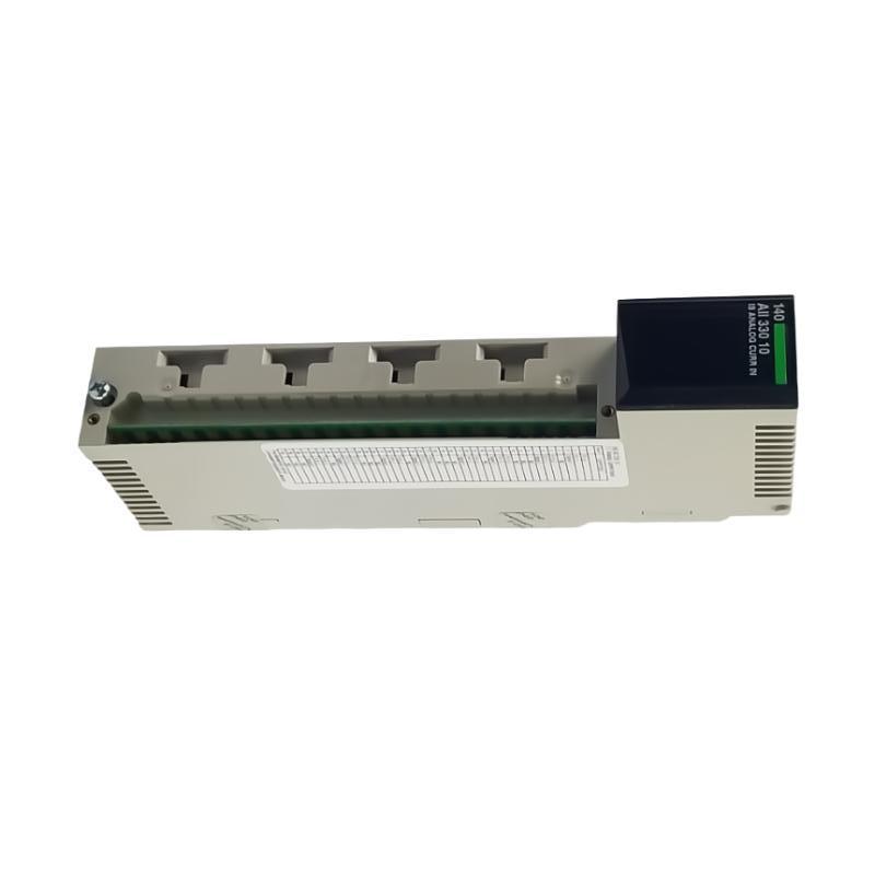
The Schneider Electric 140AII33010C Modicon Quantum intrinsically safe current input module is an eight-channel analog input module used to acquire current signals from compatible field transmitters in industrial process control systems. It supports configurable 4–20 mA, 0–20 mA, and 0–25 mA input ranges and is designed for applications that require approved intrinsically safe interfacing with field instruments.
When the 140AII33010C experiences a channel fault, incorrect process values, broken-wire indications, or communication problems, troubleshooting should begin with the field circuit and module status indicators. Incorrect range settings, wiring faults, transmitter power problems, PLC scaling errors, and genuine hardware failures can produce similar symptoms. A structured diagnostic process helps engineers identify the actual cause and restore reliable measurement without unnecessary module replacement.
Table of Contents
- 1. Common Fault Symptoms
- 2. Safety Requirements
- 3. Understanding Module Status Indicators
- 4. Step-by-Step Troubleshooting Procedure
- 5. Current Signal and Wiring Faults
- 6. PLC Configuration and Data Problems
- 7. Rack, Communication, and Hardware Faults
- 8. Repair and Module Replacement
- 9. Preventive Maintenance
- 10. Frequently Asked Questions
- 11. Technical Summary
1. Common Fault Symptoms
The first step in diagnosing the 140AII33010C is to determine whether the problem affects a single channel, multiple channels, or the complete I/O module. This distinction helps narrow the possible causes.
| Fault symptom | Possible cause | Initial diagnostic action |
|---|---|---|
| Input value remains at zero | Open circuit, transmitter power failure, incorrect wiring, or channel configuration error | Verify the field signal and selected current range |
| Red channel indicator is illuminated | Broken wire, out-of-range signal, or another documented channel fault | Identify the affected channel and inspect its diagnostic status |
| Red F indicator is illuminated | A channel fault has been detected, such as a broken wire or out-of-range condition | Check the individual channel indicators and field circuits |
| Reading is consistently inaccurate | Incorrect current range, transmitter configuration, or PLC scaling | Compare the field signal, raw input value, and engineering value |
| Reading fluctuates unexpectedly | Unstable transmitter output, loose connection, interference, or process variation | Inspect signal integrity and compare the transmitter output with the PLC trend |
| All channels become unavailable | Rack communication problem, module configuration mismatch, or system-level fault | Review PLC diagnostics and rack status |
| Fault returns after maintenance | Intermittent wiring, incorrect configuration, or unresolved field-device problems | Review the previous corrective action and repeat the diagnostic sequence |
These symptoms are not proof of a failed module. Confirm the signal conditions and the documented meaning of each indicator before making hardware changes.
2. Safety Requirements
The 140AII33010C is intended for intrinsically safe applications. Troubleshooting must therefore consider both electrical safety and the certification requirements of the complete field circuit.
- Use authorized personnel familiar with the applicable hazardous-area installation requirements.
- Follow site lockout/tagout procedures and verify the required safe state before disconnecting wiring or removing the module.
- Never hot-swap the 140AII33010C. De-energize the equipment in accordance with the applicable hardware instructions before removal or installation.
- Do not disconnect or reconnect field wiring in a hazardous area unless the approved procedure specifically permits the work under the existing conditions.
- Use appropriately rated test equipment and follow the approved test procedure for intrinsically safe circuits.
- Do not bypass protective logic, interlocks, or process alarms to conceal an input fault.
- Do not substitute an unverified module or field instrument into a certified loop.
Intrinsic safety depends on the approved combination of equipment, wiring, and circuit parameters. A successful electrical measurement does not, by itself, demonstrate that a hazardous-area circuit remains compliant.
3. Understanding Module Status Indicators
The 140AII33010C has an Active indicator, an F fault indicator, and individual channel indicators numbered 1 through 8. These indicators help maintenance personnel determine whether the module is communicating and which input may require attention.
| Indicator | Documented meaning when illuminated | Recommended response |
|---|---|---|
| Active — green | Module communication with the PLC is present | Continue with channel-level diagnosis if the measurement is incorrect |
| F — red | A fault condition has been detected, including supported broken-wire or out-of-range conditions | Inspect individual channel indicators and check the applicable diagnostic definitions |
| Channel 1–8 — red | The indicated channel has a documented fault condition, such as a broken wire or out-of-range signal | Check the associated transmitter, field wiring, and channel configuration |
For this module, broken-wire detection is associated with the 4–20 mA range, while out-of-range monitoring also depends on the selected mode. Consult the exact hardware documentation for the installed revision before interpreting a particular indicator combination.
4. Step-by-Step Troubleshooting Procedure
Step 1: Record the original fault condition
Before making changes, record the affected channel, process variable, expected current range, displayed value, module indicator status, and any PLC diagnostic message. Determine whether the fault started after instrument maintenance, wiring changes, software edits, a power interruption, or module replacement.
This information helps distinguish an electrical fault from a configuration problem and provides a baseline for verifying the repair.
Step 2: Identify whether the fault is channel-specific
If only one channel is affected, begin with its transmitter, cable, terminal connections, and configuration. If several channels fail simultaneously, investigate common causes such as rack communication, shared field power arrangements, configuration changes, or environmental damage.
Do not move field wires between channels as an informal test. In intrinsically safe applications, circuit changes must follow the approved drawings and safety procedures.
Step 3: Check the field instrument
Verify that the connected transmitter is powered and operating normally. Inspect its local display, diagnostic status, configured output range, and process measurement where available.
For example, a transmitter may be configured for 4–20 mA while the PLC channel expects 0–20 mA. The transmitter may be operating correctly even though the displayed engineering value is wrong.
Step 4: Inspect the current loop
Under the approved electrical safety procedure, check the field cable, terminal strip, polarity, conductor continuity, and relevant power arrangements. Verify that the signal path matches the module’s approved wiring diagram.
The module provides power for compatible intrinsically safe transmitters. Consequently, troubleshooting must account for the documented field terminal arrangement and must not assume that the module is wired like a generic passive current input.
Step 5: Verify channel configuration
Check the configured current range for the affected channel. Confirm that the selected range corresponds to the transmitter output and that the software configuration matches the installed module.
The module supports 4–20 mA, 0–20 mA, and 0–25 mA ranges. Do not change the range simply to eliminate an indicator. The correct setting must match the instrument specification and intended measurement.
Step 6: Compare raw input data with the displayed value
Inspect the input value available to the PLC before application scaling. If the raw value is plausible but the engineering value is incorrect, investigate the program’s conversion logic, channel mapping, data interpretation, and HMI settings.
Step 7: Check rack and module diagnostics
Confirm that the PLC recognizes the module in the correct rack and slot. Review the applicable controller diagnostics and verify whether other modules in the same rack are communicating normally.
Step 8: Verify the corrective action
After correcting a confirmed issue, repeat the relevant checks and verify that the input value is stable and appropriate for the applied signal. Record the result and confirm that alarms and process displays behave as intended before returning the equipment to normal operation.
5. Current Signal and Wiring Faults
5.1 Broken-wire indication in a 4–20 mA circuit
A broken-wire indication may result from an open conductor, loose terminal, disconnected transmitter, or interruption in the approved field circuit. Check the channel indicator and confirm the meaning of the status using the module documentation.
Inspect the complete loop rather than focusing only on the module terminal. A fault may be located at the field instrument, junction box, marshalling point, cable route, or terminal strip.
5.2 Input value is too low
A low reading can result from an actual process condition, a transmitter configured with the wrong lower range, a power problem, a wiring fault, or a mismatch between the selected module range and the instrument output.
Compare the transmitter’s configured range with the channel settings. If the instrument output is confirmed to be correct, investigate the signal path and PLC data interpretation before replacing the input module.
5.3 Input value is too high
An unexpectedly high value may indicate an out-of-range signal, incorrect scaling, an incorrect transmitter upper range, or a field wiring problem. Check the instrument configuration and raw PLC input data.
Do not assume that a high value is an instrument failure. In some applications, the measurement may reflect a genuine process condition requiring an operational response.
5.4 Current signal is unstable
Fluctuating readings can originate from an unstable transmitter, intermittent connections, electrical interference, or genuine changes in the process variable. Inspect cable routing, shielding, terminal condition, and the transmitter’s own diagnostic information.
The module uses a low-pass input filter with a nominal cutoff of approximately 15 Hz. This filtering does not eliminate every type of interference or compensate for defective wiring. Any configuration or hardware change should follow the product documentation and plant standards.
5.5 Multiple channels show similar errors
If several input channels become abnormal at the same time, look for a common cause. Possible factors include a shared supply issue, wiring work affecting several loops, a rack-level problem, or a configuration change affecting multiple channels.
Compare the affected channels with any unaffected channels and examine recent maintenance records. A common pattern often provides more useful diagnostic information than replacing one module immediately.
6. PLC Configuration and Data Problems
6.1 Incorrect current range
The configured range determines how the input signal is represented in the PLC. A mismatch between the channel configuration and transmitter output can cause offset errors or incorrect process values.
Confirm the intended range from the instrument datasheet and approved control documentation. After correcting a verified configuration error, check the reading at a known or controlled operating condition.
6.2 Incorrect raw data interpretation
The module supports documented data representations with different raw count ranges. For example, the documentation describes ranges using count values for 4–20 mA, 0–20 mA, and 0–25 mA configurations. The selected format must be interpreted correctly by the PLC program.
Do not assume that all Schneider Electric analog input modules use the same raw data representation. Verify the module’s configuration and the programming software’s interpretation before changing conversion constants.
6.3 Incorrect engineering-unit scaling
A correct electrical input may produce an incorrect displayed measurement when the PLC uses the wrong engineering limits, conversion formula, or data address. This is particularly common after replacing a module or copying logic from another application.
The general linear scaling equation is:
Engineering Value =
(Raw Input - Raw Low)
× (Engineering High - Engineering Low)
÷ (Raw High - Raw Low)
+ Engineering Low
This equation is a general example, not a model-specific programming instruction. The raw limits must match the actual configured range and data format.
6.4 Incorrect rack or channel mapping
If the PLC program reads the wrong slot or channel address, the displayed process value may remain static or follow another instrument’s signal. Confirm the physical module location, project configuration, channel assignment, and application variable mapping.
After a replacement, compare the new hardware arrangement with the approved rack layout and program documentation. Do not assume that a similar catalog number automatically guarantees an identical configuration.
7. Rack, Communication, and Hardware Faults
7.1 Active indicator is not illuminated
If the Active indicator is not illuminated, investigate whether the module is communicating with the PLC. Check the rack and controller status, the module’s installed position, and any reported I/O configuration errors.
Before handling the module or its connectors, follow the required isolation procedure. Do not reseat the module while energized.
7.2 F indicator remains illuminated
The F indicator can report a fault detected on one or more channels, including supported broken-wire and out-of-range conditions. Inspect the individual channel indicators to help identify the affected input circuits.
If the F indicator remains on after a verified field fault has been corrected, check the actual signal, channel range, and diagnostic status again. Do not assume that the module has failed solely because the indicator remains illuminated.
7.3 All channels show abnormal readings
When all channels fail together, review the rack configuration, PLC communication, module power requirements, and any common field wiring or supply arrangements. Check whether other modules in the rack are operating correctly.
If the controller reports a module configuration or communication problem, resolve that problem before performing channel-by-channel signal testing.
7.4 Suspected internal hardware failure
Hardware failure becomes a stronger possibility when the field instruments, wiring, channel settings, raw data interpretation, and rack operation have all been verified and the symptom remains reproducible.
Because the 140AII33010C is a discontinued product, obtain a replacement only after confirming the full catalog number, hardware compatibility, and applicable hazardous-area certification. Do not substitute an ordinary analog input module for an intrinsically safe module without a formally reviewed system redesign.
8. Repair and Module Replacement
The 140AII33010C is a specialized intrinsically safe input module. Troubleshooting should prioritize correction of external wiring and configuration issues before replacing the hardware.
- Record the existing module reference, rack position, channel settings, and fault indicators.
- Place the process in a safe condition and follow the approved lockout/tagout and hazardous-area work procedures.
- Verify the absence of the relevant hazardous energy before removing the module or disconnecting field wiring.
- Inspect the terminal strip, cable connections, and rack connector for visible damage or contamination.
- Confirm that any replacement is suitable for the existing system and approved intrinsic safety design.
- Install the module according to the applicable hardware instructions. Do not hot-swap it.
- Restore power only after the installation has been checked and all required safety inspections are complete.
- Verify PLC recognition, channel configuration, input readings, and fault handling.
- Record the final test results and the reason for replacement or repair.
If the same fault remains after installing a verified compatible module, investigate the field circuit, program configuration, and rack system again. Replacing the module without correcting the original cause may lead to repeated downtime.
9. Preventive Maintenance
Preventive maintenance helps reduce recurring analog input faults and supports reliable process monitoring in hazardous-area installations.
- Inspect field cables, terminal strips, and cabinet conditions during scheduled maintenance.
- Keep current loop drawings, module configuration records, and channel assignments accurate.
- Verify transmitter calibration and output configuration according to the plant maintenance schedule.
- Review recurring broken-wire and out-of-range indications for common causes.
- Maintain a verified backup of the PLC application and hardware configuration.
- Use approved procedures when testing intrinsically safe circuits.
- Confirm catalog numbers and certification requirements before sourcing replacement equipment.
- Document every module replacement and functional test.
Schneider Electric lists the 140AII33010C as discontinued and identifies November 19, 2024, as the end-of-standard-service date. Facilities using this module should plan spare-parts management and long-term migration carefully, while preserving the required intrinsic safety and control-system functions.
10. Frequently Asked Questions
Why is the 140AII33010C input reading zero?
Possible causes include an open field circuit, transmitter power problems, incorrect wiring, a mismatched current range, or PLC addressing errors. Verify the field signal and channel configuration before concluding that the module has failed.
What does the red F indicator mean?
The F indicator reports a detected fault. For this module, documented conditions include a broken wire in 4–20 mA mode or an out-of-range condition. Check the individual channel indicators and the applicable hardware manual to identify the affected input.
What do the red channel indicators mean?
A red channel indicator identifies a fault associated with that input, such as a broken wire or an out-of-range condition. Investigate the corresponding transmitter, wiring, and configured range.
Can the 140AII33010C be removed while the PLC is running?
Do not hot-swap this module. Follow the specified shutdown and isolation procedure before removing or installing it, particularly because it is intended for intrinsically safe applications.
Why does the module show a fault even though the transmitter appears to be working?
The transmitter may be operating locally while the signal path remains open, incorrectly wired, or outside the configured range. The channel configuration or signal interpretation may also be incorrect. Verify the complete loop and diagnostic information.
Can I replace the module with another Quantum analog input module?
Not automatically. The replacement must support the required current input function and satisfy the existing hazardous-area certification and system design. An ordinary analog input module should not be treated as a direct replacement for an intrinsically safe module without engineering review.
11. Technical Summary
The Schneider Electric 140AII33010C is an eight-channel Modicon Quantum intrinsically safe current input module supporting configurable 4–20 mA, 0–20 mA, and 0–25 mA signals. Reliable fault diagnosis requires checking the field instrument, current loop, channel configuration, PLC data interpretation, module indicators, and rack communication in a logical sequence.
The Active, F, and individual channel indicators provide useful diagnostic information, but they should always be interpreted according to the product documentation. Broken-wire and out-of-range conditions can arise from field wiring or configuration problems and do not automatically indicate internal hardware failure.
For maintenance engineers, the priorities are to follow intrinsically safe work procedures, verify the complete signal path, document the corrective action, and confirm normal operation before returning the process to service. Since the 140AII33010C is discontinued, replacement planning should include hardware compatibility, spare-parts availability, and preservation of the approved hazardous-area design.