

ProductPRODUCT
Featured products



Contact Us

- Schneider
- BCH1001O32A1C
- Servo Motor
- France
- 153.5 mm
- 4.3 kg
- Xiamen, China
- New & In Stock
- T/T, PayPal, Western Union
- 1 Year
- 1-3 Working Days
- DHL, UPS, TNT, FedEx and EMS.
- 24-Hour Service
- COO
- 35
Our advantage

Global Logistics
We have a 10-year logistics and express cooperation agreement, so our products can be shipped to any place in the world.

Brand new and original
Our products are imported in bulk from the place of origin. Because of the cooperative relationship, our products are all original and 100% new.

24-hour service
We provide 7*24 hours service to our customers. We will be there whenever you need us.

Price advantage
All our products are priced very favorably because we have our own warehouse and supply.
| Company Information | |||
| [email protected] | |||
| Mobile | +8615980777398 | ||
| +8615980777398 | |||
| 15980777398 |
Product Overview
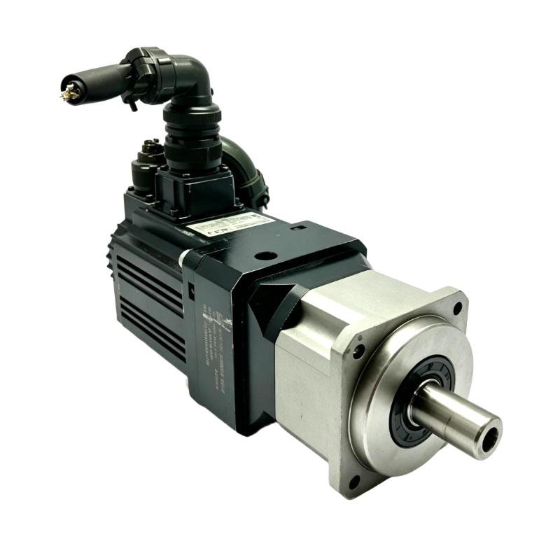
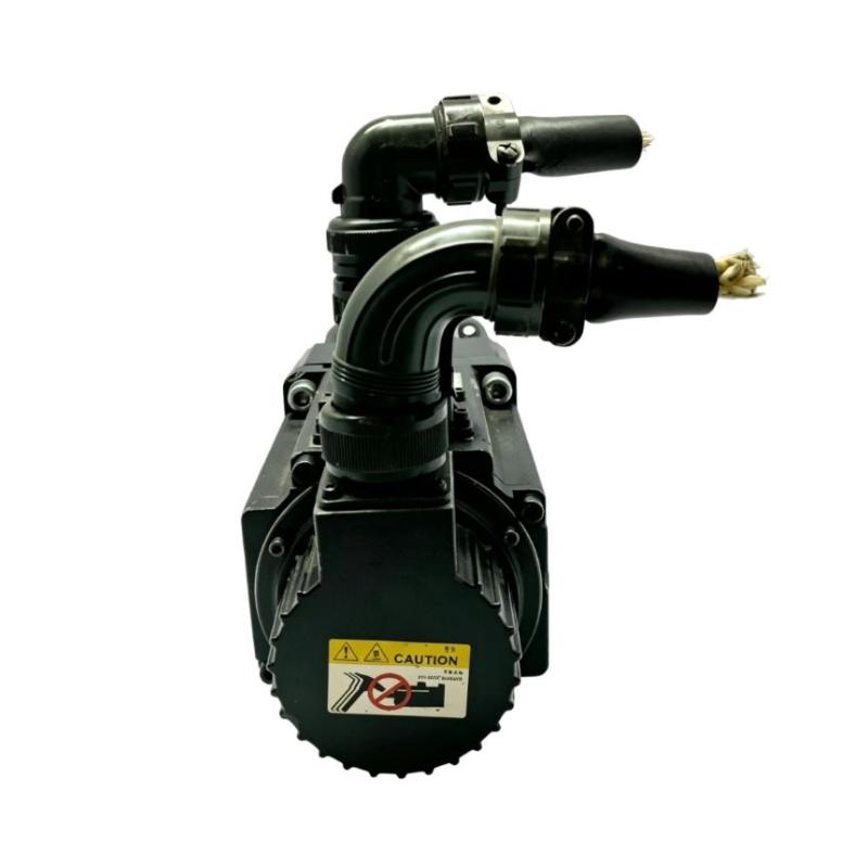
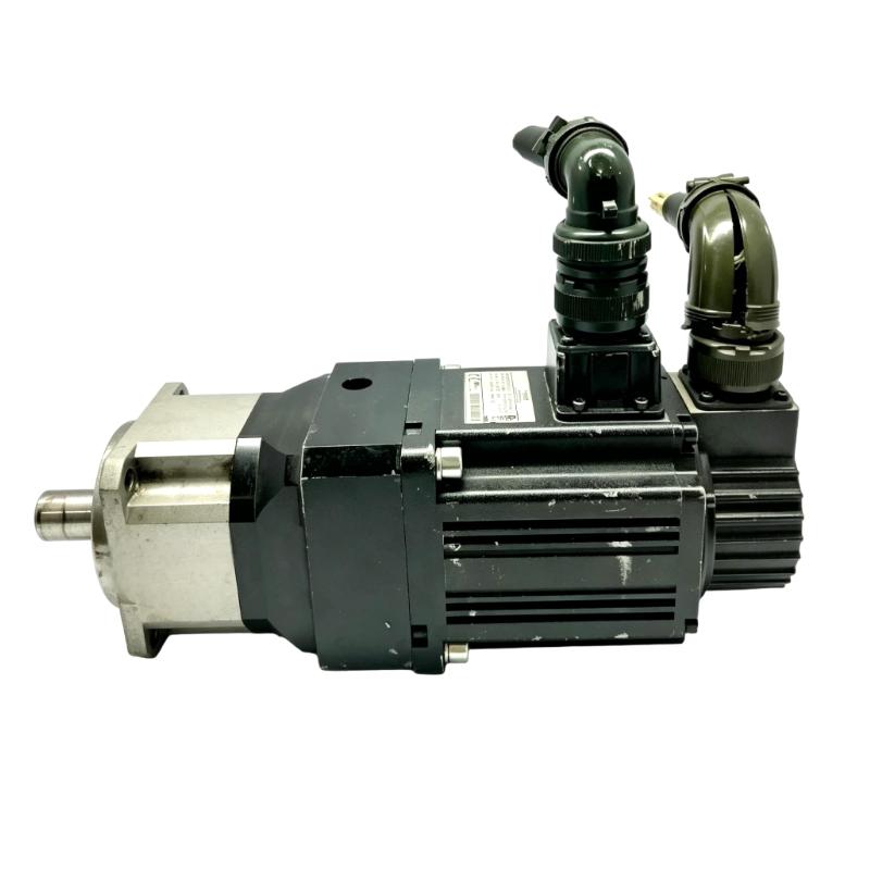
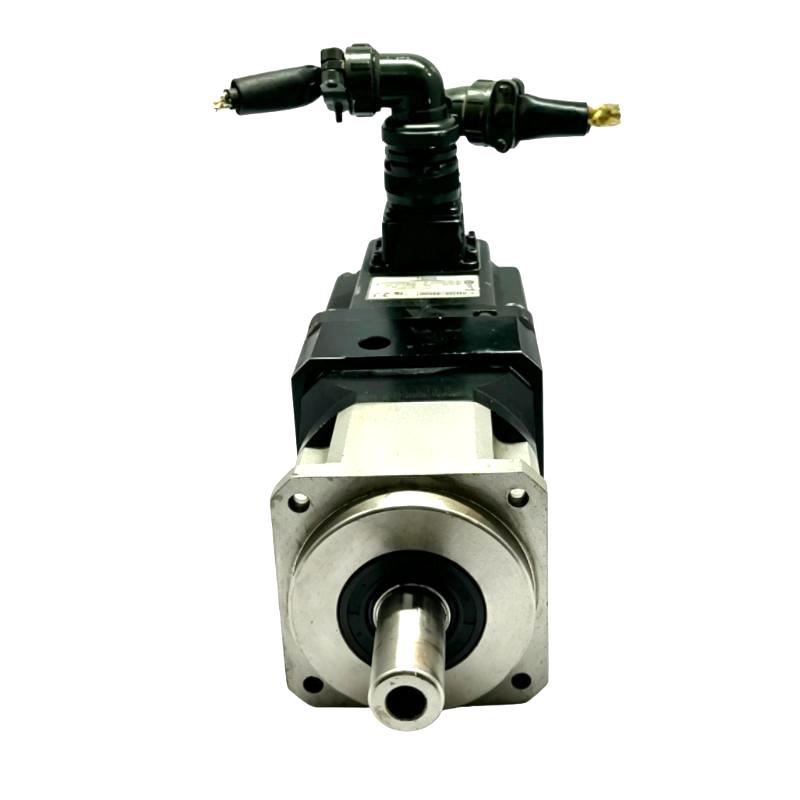
The Schneider Electric BCH1001O32A1C Servo Motor is an industrial servo motor designed for use in automated motion-control systems where controlled motor movement, repeatable positioning, and coordinated machine operation are required. As part of Schneider Electric’s BCH servo motor family, this motor can be integrated with a compatible Schneider servo drive and motion-control architecture to provide closed-loop motor control for industrial machinery.
Servo motors are commonly used in applications where conventional induction motors or standard variable-speed motors cannot provide the required positioning accuracy, dynamic response, or synchronized motion. In a typical automation system, the servo motor works together with a servo drive, controller, feedback device, and mechanical transmission to convert control commands into precise rotary movement.
The BCH1001O32A1C has a supplied length of 153.5 mm and a weight of 4.3 kg. These physical specifications are important when designing machine layouts, selecting mounting locations, planning replacement work, and determining mechanical clearance.
The exact electrical and performance characteristics of an individual servo motor should always be confirmed against the applicable product documentation and nameplate. Parameters such as rated power, rated torque, maximum speed, encoder configuration, brake configuration, shaft dimensions, mounting arrangement, and connector details should not be assumed solely from the model number.
Technical Specifications
| Parameter | Specification |
|---|---|
| Manufacturer | Schneider Electric |
| Model | BCH1001O32A1C |
| Product Type | Servo Motor |
| Product Family | BCH Servo Motor Series |
| Motor Application | Industrial Motion Control |
| Control Method | Closed-Loop Servo Control |
| Feedback | Compatible Servo Feedback System |
| Length | 153.5 mm |
| Weight | 4.3 kg |
| Installation | Machine / Panel-Mounted Servo System |
| Typical Applications | Industrial Automation, Positioning, Robotics, Packaging, Material Handling |
Note: Exact electrical ratings, torque, speed, feedback device, brake configuration, shaft dimensions, connector arrangement, and mounting specifications should be verified from the specific BCH1001O32A1C documentation or motor nameplate before engineering or replacement work.
What Is the Schneider BCH1001O32A1C Servo Motor?
The Schneider BCH1001O32A1C is a servo motor intended to operate as part of a coordinated industrial motion-control system.
Unlike a conventional motor that may primarily be controlled by applying a selected voltage or frequency, a servo motor is normally operated as part of a feedback-controlled system. The controller establishes the desired movement, while the servo drive regulates the motor based on feedback from the motor’s position or speed sensing system.
A typical servo architecture can be represented as:
Motion Controller → Servo Drive → BCH1001O32A1C Servo Motor → Mechanical Load
with feedback returning through the servo system:
Servo Motor → Feedback Device → Servo Drive / Controller
This closed-loop structure allows the automation system to continuously compare commanded movement with actual motor behavior.
Servo Motor Working Principle
The BCH1001O32A1C operates within a closed-loop motion-control architecture.
The controller first generates a motion command. Depending on the machine application, the command can represent a required position, velocity, acceleration, or coordinated movement.
The servo drive then processes the command and supplies controlled electrical power to the motor.
During operation, feedback information is returned to the drive. The drive compares the commanded condition with the actual motor response and adjusts motor operation accordingly.
This process can be summarized as:
- Motion command is generated.
- Servo drive receives the command.
- Electrical power is supplied to the motor.
- Motor produces mechanical rotation.
- Feedback reports actual motor behavior.
- Servo drive calculates the control response.
- Motor output is continuously corrected.
- Machine movement follows the programmed motion profile.
This continuous feedback loop is one of the main characteristics that distinguishes servo systems from simpler open-loop motor-control arrangements.
Role in Industrial Automation
The BCH1001O32A1C can form one part of a complete automated motion system.
In an industrial machine, the servo motor is responsible for converting electrical control signals into mechanical movement. The controller determines what the machine should do, the servo drive manages motor current and motion response, and the motor delivers the resulting mechanical rotation.
A complete system may include:
- PLC or motion controller
- Servo drive
- BCH1001O32A1C servo motor
- Motor feedback system
- Mechanical coupling
- Gearbox or transmission
- Linear actuator
- Machine mechanism
- HMI
- Safety system
- Industrial communication network
The performance of the complete system depends on the compatibility and correct configuration of all these components.
Industrial Applications
The BCH1001O32A1C can be considered for industrial applications requiring controlled rotary motion and repeatable machine movement.
Typical servo applications include:
Packaging Machinery
Servo motors are frequently used in packaging equipment for synchronized feeding, cutting, sealing, indexing, and positioning.
Material Handling
Servo-controlled mechanisms can provide controlled acceleration, deceleration, and positioning in conveyors, transfer mechanisms, and automated handling systems.
Machine Tools
Servo systems are commonly used in machine-tool applications where accurate and coordinated movement is required.
Assembly Automation
Automated assembly equipment may use servo motors for positioning components, moving tooling, and coordinating multiple machine axes.
Robotics
Servo motors provide the controlled rotary movement required by many robotic and automated mechanisms.
Printing Equipment
Printing and converting machines can use servo systems for synchronized rollers, feeding mechanisms, and positioning operations.
Textile Machinery
Servo motion control can be used for controlled material movement, tension management, and synchronization between machine sections.
General Factory Automation
The motor can be integrated into automation equipment requiring controlled speed, positioning, and coordinated movement.
Servo System Architecture
A typical Schneider servo system using the BCH1001O32A1C can be divided into several functional layers.
| System Component | Typical Function |
|---|---|
| PLC / Motion Controller | Generates motion commands |
| Servo Drive | Controls motor power and feedback loop |
| BCH1001O32A1C | Converts electrical energy into mechanical rotation |
| Feedback System | Provides actual motor position or speed information |
| Mechanical Transmission | Transfers motor torque to the machine |
| HMI | Provides operator control and diagnostics |
| Safety System | Provides machine safety functions |
| Industrial Network | Transfers control and status information |
The exact architecture depends on the machine design and selected Schneider Electric control equipment.
Installation Guidelines
Correct mechanical and electrical installation is essential for reliable servo operation.
Before installing the BCH1001O32A1C, verify:
- Motor model
- Nameplate information
- Servo drive compatibility
- Feedback compatibility
- Mechanical mounting arrangement
- Shaft and coupling requirements
- Cable connections
- Connector orientation
- Motor rotation requirements
- Environmental conditions
The supplied motor length is 153.5 mm, while the listed weight is 4.3 kg. These values should be considered when designing the machine mounting structure and calculating handling requirements.
Mechanical Installation
The motor should be securely mounted to a suitable machine structure.
Important mechanical considerations include:
Mounting Alignment
The motor shaft and driven mechanism should be correctly aligned. Excessive angular or radial misalignment can increase mechanical stress and bearing loading.
Coupling
If a flexible coupling is used, it should be selected according to the actual motor and machine requirements.
Mechanical Load
The connected load should remain within the applicable mechanical limits of the motor.
Vibration
Excessive machine vibration can affect motor bearings, feedback devices, connectors, and mechanical transmission components.
Clearance
Sufficient space should be provided around the motor for cable routing, maintenance, inspection, and heat dissipation.
The exact mounting pattern and shaft dimensions should be confirmed from the applicable Schneider documentation rather than inferred from the model number.
Servo Drive Integration
A servo motor normally requires a compatible servo drive to control its operation.
The drive provides controlled electrical power while processing feedback information from the motor.
During integration, engineers should verify:
- Servo drive compatibility
- Motor identification
- Feedback connection
- Motor cable compatibility
- Power requirements
- Control interface
- Communication configuration
- Motor rotation direction
- Acceleration and deceleration settings
- Machine safety functions
Using an incorrect motor-drive combination can result in poor motion performance, drive faults, overheating, or improper feedback operation.
Commissioning Procedure
A structured commissioning procedure helps reduce startup problems.
Step 1: Verify the Motor
Confirm that the installed motor is the correct BCH1001O32A1C model.
Step 2: Inspect Mechanical Installation
Check the mounting arrangement, shaft coupling, mechanical alignment, and fasteners.
Step 3: Check Motor Cables
Inspect motor power and feedback cables for damage, loose connections, incorrect routing, or connector problems.
Step 4: Confirm Drive Configuration
The servo drive should be configured for the correct motor and feedback system.
Step 5: Check Feedback
Verify that the drive receives valid feedback information before enabling full machine operation.
Step 6: Perform Low-Speed Testing
Initial movement should be performed at a controlled speed where the motor and mechanical system can be observed safely.
Step 7: Verify Direction
Confirm that the actual motor rotation corresponds to the programmed machine direction.
Step 8: Test Motion Profiles
Gradually verify acceleration, deceleration, positioning, and synchronization functions.
Step 9: Monitor Operating Conditions
During commissioning, observe motor temperature, drive status, abnormal noise, vibration, and fault indications.
Troubleshooting the BCH1001O32A1C
Servo-system faults should be investigated as a complete system rather than assuming that the motor itself is defective.
Motor Does Not Rotate
Possible causes include:
- Servo drive not enabled
- Incorrect drive configuration
- Missing motor power
- Feedback fault
- Safety circuit active
- Incorrect control command
- Cable or connector problem
- Mechanical obstruction
Check the drive status and fault information before replacing the motor.
Servo Fault During Acceleration
Possible causes may include:
- Excessive acceleration demand
- Mechanical load problems
- Incorrect motor parameters
- Feedback abnormalities
- Cable problems
- Drive configuration issues
Reducing the acceleration demand temporarily during testing can help distinguish between control and mechanical problems.
Positioning Error
Positioning problems may result from:
- Incorrect motion parameters
- Mechanical backlash
- Coupling problems
- Excessive machine load
- Feedback problems
- Incorrect tuning
- Mechanical slippage
The entire motion chain should be inspected.
Excessive Motor Temperature
Possible causes include:
- Excessive load
- High-duty-cycle operation
- Insufficient cooling
- Mechanical friction
- Incorrect servo configuration
- Excessive acceleration or deceleration
Motor temperature should be evaluated against the applicable operating specifications.
Abnormal Noise or Vibration
Inspect:
- Motor mounting
- Shaft alignment
- Coupling
- Bearings
- Mechanical transmission
- Load characteristics
- Servo tuning
Mechanical problems should be corrected before changing control parameters unnecessarily.
Preventive Maintenance
Although servo motors are designed for industrial operation, regular inspection can help maintain machine reliability.
Inspect Motor Connections
Check power and feedback connectors for looseness, contamination, mechanical damage, or cable strain.
Inspect Mechanical Couplings
Verify that couplings remain properly aligned and securely mounted.
Monitor Vibration
Unexpected increases in vibration can indicate mechanical wear, imbalance, alignment problems, or bearing-related issues.
Monitor Temperature
Abnormal temperature increases can indicate excessive load, insufficient cooling, or mechanical problems.
Review Drive Diagnostics
Servo drive alarms and historical fault information can provide useful indications of developing problems.
Keep the Installation Clean
Dust, oil, moisture, and other contaminants should be controlled according to the environmental requirements of the equipment.
Replacement Considerations
When replacing a Schneider BCH1001O32A1C Servo Motor, the complete model number should be checked carefully.
Important identification information includes:
- Full motor model
- Nameplate information
- Motor family
- Feedback configuration
- Brake configuration, if applicable
- Connector arrangement
- Shaft configuration
- Mounting arrangement
- Compatible servo drive
- Machine application
The replacement motor should not be selected based only on physical dimensions.
The listed 153.5 mm length and 4.3 kg weight are useful for mechanical planning, but electrical and motion-control compatibility must also be confirmed.
Physical Dimensions and Handling
The BCH1001O32A1C has a listed length of:
153.5 mm
Its listed weight is:
4.3 kg
These parameters are useful for:
- Machine layout
- Cabinet and equipment planning
- Mechanical clearance
- Shipping preparation
- Spare-parts inventory
- Installation handling
- Replacement planning
The stated length should not be interpreted as the complete dimensional envelope of the motor. Additional dimensions such as shaft projection, flange dimensions, connector clearance, and mounting-hole spacing should be obtained from the applicable mechanical drawing.
Engineering Best Practices
For reliable BCH1001O32A1C operation, engineers should consider the complete motion-control system rather than the motor alone.
Match the Motor and Drive
Always verify that the servo drive is compatible with the selected motor and feedback configuration.
Maintain Cable Separation
Motor power cables should be routed appropriately relative to sensitive control and communication wiring.
Protect Feedback Signals
Feedback connections are important to closed-loop control performance. Proper cable routing and secure connectors can reduce signal problems.
Verify Mechanical Load
The motor should be selected and operated according to the actual machine load, acceleration, duty cycle, and motion profile.
Document Configuration
Record motor model, drive settings, machine parameters, and commissioning results. This can simplify future maintenance and replacement.
Use Controlled Commissioning
Initial testing should be performed at reduced machine conditions before full production operation.
Compatible Automation Components
Depending on the machine architecture, the BCH1001O32A1C can be integrated with a broader Schneider Electric automation environment containing:
- Schneider Electric servo drives
- Motion controllers
- Modicon PLC systems
- Industrial HMIs
- Ethernet-based automation networks
- Machine safety systems
- Motor feedback interfaces
- Servo motor power cables
- Feedback cables
- Mechanical couplings
- Gearboxes
- Linear motion mechanisms
The exact compatible components should be confirmed according to the specific motor revision and system configuration.
Recommended Related Schneider Models
| Model | Product Type | General Application |
|---|---|---|
| BCH1001O32A1C | Servo Motor | Industrial Motion Control |
| BCH1001O32A1C-family Motors | Servo Motor | Machine Automation |
| BCH Series Servo Motors | Servo Motor Family | Positioning and Motion Control |
| Schneider Servo Drives | Servo Drive | Closed-Loop Motor Control |
| Modicon Motion Controllers | Motion Controller | Coordinated Machine Motion |
The related models above represent product categories or motor families rather than direct replacement recommendations. Exact replacement compatibility should always be confirmed using the complete part number and system requirements.
Key Advantages
- Designed for industrial servo motion applications
- Supports closed-loop motion-control architectures
- Suitable for automated positioning systems
- Can be integrated with compatible Schneider servo drives
- Compact mechanical form with a listed length of 153.5 mm
- Listed weight of 4.3 kg
- Suitable for coordinated machine motion
- Applicable to packaging, handling, assembly, and general automation
- Supports precise control when correctly matched with the drive and feedback system
- Suitable for integration into modern industrial automation equipment
Technical FAQs
What is the Schneider BCH1001O32A1C?
The Schneider BCH1001O32A1C is a Schneider Electric servo motor intended for integration into industrial closed-loop motion-control systems.
What is the length of the BCH1001O32A1C?
The supplied length is 153.5 mm.
How much does the BCH1001O32A1C weigh?
The supplied weight is 4.3 kg.
What is the BCH1001O32A1C used for?
It can be used in industrial automation systems requiring controlled motor movement, positioning, speed regulation, and coordinated machine motion.
Does the BCH1001O32A1C work with a servo drive?
Yes, a servo motor is normally operated with a compatible servo drive. The exact drive compatibility should be confirmed for the complete motor model and feedback configuration.
What should be checked when replacing the motor?
The complete model number, feedback configuration, brake configuration where applicable, shaft arrangement, mounting configuration, cable connections, and servo-drive compatibility should all be verified.
Can the motor dimensions be used to determine compatibility?
Physical dimensions alone are not sufficient. The supplied 153.5 mm length and 4.3 kg weight are useful for mechanical planning, but electrical, feedback, mechanical, and drive compatibility must also be confirmed.
What can cause servo motor positioning problems?
Positioning problems can result from incorrect tuning, mechanical backlash, coupling problems, excessive load, feedback faults, incorrect configuration, or problems elsewhere in the motion-control system.
Conclusion
The Schneider Electric BCH1001O32A1C Servo Motor is an industrial motion-control component intended to operate within a compatible closed-loop servo system. By working together with a servo drive, feedback system, controller, and mechanical load, the motor can provide controlled rotary motion for automated machinery.
The supplied physical specifications are 153.5 mm in length and 4.3 kg in weight, making these values useful for machine layout, installation planning, handling, and replacement logistics.
For reliable operation, the BCH1001O32A1C should be treated as part of a complete motion-control architecture. Correct motor-drive matching, proper mechanical alignment, secure feedback connections, appropriate commissioning, and regular maintenance are important for achieving stable and repeatable machine performance.
When sourcing or replacing the BCH1001O32A1C, the complete model designation and applicable system documentation should be checked before installation. Exact electrical ratings, feedback configuration, mounting dimensions, shaft characteristics, and performance parameters should be verified for the specific motor before final engineering decisions are made.