

ProductPRODUCT
Featured products



Contact Us
- Schneider
- ATS490C32Y
- Soft Starter
- France
- 443 x 206 x 265 mm
- 19 kg
- Xiamen, China
- New & In Stock
- T/T, PayPal, Western Union
- 1 Year
- 1-3 Working Days
- DHL, UPS, TNT, FedEx and EMS.
- 24-Hour Service
- COO
- 87
Our advantage

Global Logistics
We have a 10-year logistics and express cooperation agreement, so our products can be shipped to any place in the world.

Brand new and original
Our products are imported in bulk from the place of origin. Because of the cooperative relationship, our products are all original and 100% new.

24-hour service
We provide 7*24 hours service to our customers. We will be there whenever you need us.

Price advantage
All our products are priced very favorably because we have our own warehouse and supply.
| Company Information | |||
| [email protected] | |||
| Mobile | +8615980777398 | ||
| +8615980777398 | |||
| 15980777398 |
Product Overview
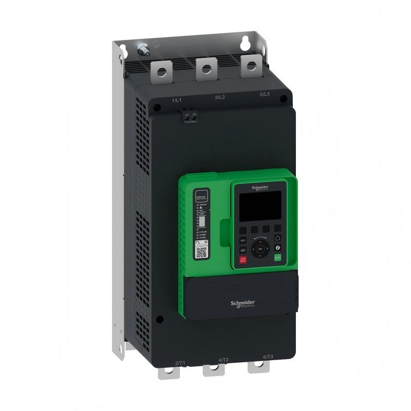
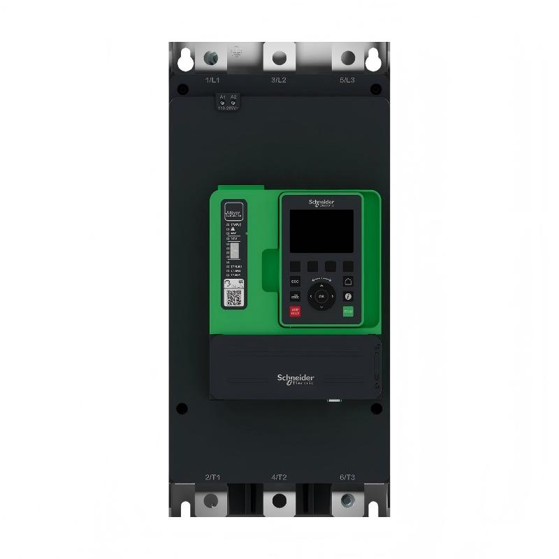
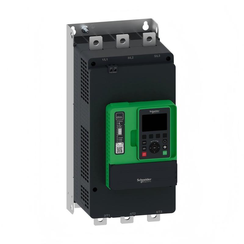
The Schneider Electric ATS490C32Y Soft Starter is a high-current motor starting and stopping solution from the Altivar Soft Starter ATS490 family. It is designed for three-phase asynchronous motors used in industrial process equipment, infrastructure systems, material handling, pumping stations, ventilation systems, compressors, mixers, crushers, and other demanding motor-driven machinery.
The ATS490C32Y provides controlled motor acceleration and deceleration rather than relying on an abrupt direct-on-line starting process. This approach can reduce mechanical shock, manage starting current, and provide a smoother transition between stopped and running conditions.
The ATS490C32Y has a 320 A normal-duty operational current rating and supports motor supply voltages from 208 to 690 V AC. For heavy-duty applications, the applicable current rating is lower, so the actual motor and application duty must be evaluated during selection.
The model uses torque-controlled starting and incorporates an internal bypass. It can also be integrated into industrial automation systems through communication interfaces such as Modbus and Ethernet-based protocols.
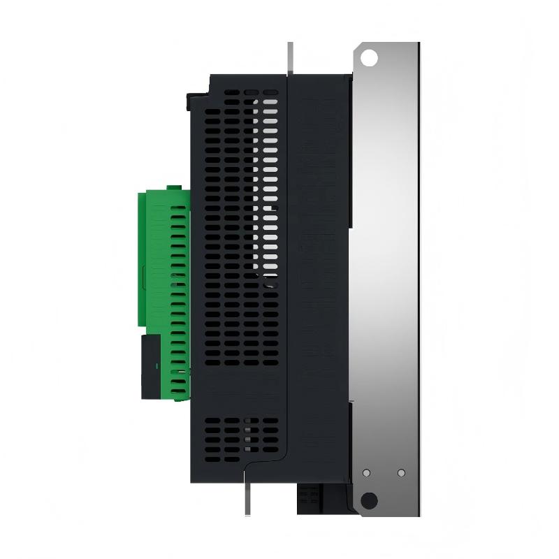
For the product information supplied for this model, the ATS490C32Y measures 443 × 206 × 265 mm and weighs 19 kg.
Product Identification
| Parameter | Specification |
|---|---|
| Manufacturer | Schneider Electric |
| Product Family | Altivar Soft Starter ATS490 |
| Model | ATS490C32Y |
| Product Type | Soft Starter |
| Rated Operational Current | 320 A Normal Duty |
| Heavy-Duty Current | 250 A |
| Motor Supply Voltage | 208–690 V AC |
| Supply Frequency | 50/60 Hz |
| Number of Phases | Three Phase |
| Motor Type | Asynchronous AC Motor |
| Starting Method | Torque Control |
| Internal Bypass | Yes |
| Installation | Vertical, Inside Enclosure |
| Dimensions | 443 × 206 × 265 mm |
| Weight | 19 kg |
| Protection Rating | IP00 |
| Communication | Modbus Serial, Modbus TCP, EtherNet/IP |
| Physical Interface | RS-485 / Ethernet |
| Typical Applications | Process and Infrastructure |
| Mounting | Cabinet / Enclosure |
Technical Specifications
| Technical Item | ATS490C32Y |
|---|---|
| Brand | Schneider Electric |
| Series | ATS490 |
| Model | ATS490C32Y |
| Soft Starter Current | 320 A Normal Duty |
| Heavy-Duty Rating | 250 A |
| Input Voltage | 208–690 V AC |
| Frequency | 50–60 Hz |
| Motor Type | Three-Phase Asynchronous Motor |
| Control Method | Torque Control |
| Bypass | Integrated |
| Communication | Modbus Serial / Modbus TCP / EtherNet/IP |
| Serial Interface | 2-Wire RS-485 |
| Ethernet | 100BASE-TX |
| Mounting Orientation | Vertical |
| Height | 443 mm |
| Width | 206 mm |
| Depth | 265 mm |
| Weight | 19 kg |
| Enclosure Requirement | Installed Inside Enclosure |
| Typical Application | Industrial Motor Control |
The 443 × 206 × 265 mm physical size places the ATS490C32Y in the same larger cabinet-mounted frame group as several other higher-current ATS490 models.
What Is the Schneider ATS490C32Y?
The ATS490C32Y is an industrial soft starter used between an AC power supply and a three-phase asynchronous motor.
A simplified installation can be represented as:
Three-Phase Power Supply
↓
Circuit Breaker / Protection
↓
ATS490C32Y Soft Starter
↓
Three-Phase AC Motor
↓
Mechanical Load
The starter controls the motor during acceleration and stopping.
With direct-on-line starting, a motor can draw a large starting current and generate a sudden torque response. For larger motors and high-inertia machinery, this can create significant stress on electrical infrastructure and mechanical components.
The ATS490C32Y provides a more controlled starting process.
This can help reduce:
- Mechanical shock
- Coupling stress
- Gearbox stress
- Belt tension changes
- Hydraulic pressure disturbances
- Starting-current impact
- Process instability
The soft starter therefore becomes an important part of the complete motor-control system rather than simply functioning as an on/off starter.
320 A Current Rating
One of the most important characteristics of the ATS490C32Y is its 320 A normal-duty operational current rating.
This makes it suitable for larger industrial motors when the motor’s actual operating current falls within the applicable rating.
For heavy-duty applications, the permissible current is lower. Therefore, selecting the starter only according to motor horsepower can result in an incorrect application.
Before selecting the ATS490C32Y, engineers should verify:
- Motor rated current
- Motor voltage
- Motor frequency
- Motor power
- Normal-duty or heavy-duty operation
- Starting frequency
- Acceleration time
- Mechanical load
- Ambient temperature
- Installation altitude
- Number of starts per hour
A motor with a high horsepower rating does not automatically require the same soft-starter rating as another motor of the same horsepower. Actual operating conditions are important.
Motor Voltage Range
The ATS490C32Y is designed for motor supplies from:
208 to 690 V AC
This allows the unit to be used across a wide range of industrial electrical systems.
The motor nameplate should always be checked before commissioning.
Important motor information includes:
- Rated voltage
- Rated current
- Frequency
- Power
- Connection
- Service conditions
The motor voltage and starter configuration must be compatible before the system is energized.
Main Functions
Controlled Motor Starting
The ATS490C32Y controls the acceleration of the motor to reduce the abrupt electrical and mechanical effects associated with direct starting.
Torque Control
Torque-oriented starting allows the acceleration behavior to be adapted to the connected mechanical load.
Controlled Stopping
The starter can provide controlled deceleration where the process requires a smoother stopping behavior.
Internal Bypass
The ATS490C32Y incorporates an internal bypass function. After the starting sequence is completed, the motor can transition into normal running operation through the bypass arrangement.
Motor Monitoring
The ATS490 platform provides monitoring functions for motor and application conditions.
Power and Energy Monitoring
The platform can provide operational information that can be useful for process monitoring and maintenance.
Communication
The ATS490C32Y supports industrial communication through Modbus Serial and Ethernet-based communication such as Modbus TCP and EtherNet/IP.
Condition Monitoring
Condition-monitoring functions can help operators identify abnormal operating conditions before they develop into more serious equipment problems.
How the ATS490C32Y Works
Stage 1 – Start Command
A start command may originate from:
- Local control
- PLC
- HMI
- SCADA
- Remote control
- Automated process sequence
The starter evaluates the relevant operating conditions before beginning motor acceleration.
Stage 2 – Controlled Acceleration
The ATS490C32Y regulates the motor’s starting behavior.
Instead of immediately connecting the motor to a full direct-start condition, the starter provides a controlled acceleration profile.
The actual acceleration behavior depends on:
- Motor characteristics
- Load characteristics
- Configuration
- Starting torque requirement
- Acceleration time
Stage 3 – Motor Reaches Operating Speed
As the motor approaches its normal operating condition, the starting sequence is completed.
The starter transitions toward normal running operation.
Stage 4 – Bypass Operation
The internal bypass allows efficient motor operation after the starting phase.
This is particularly useful in applications where the motor operates for long periods after startup.
Stage 5 – Normal Running
During normal operation, the starter and automation system can monitor operating status and diagnostic information.
Stage 6 – Controlled Stop
When a stop command is received, the ATS490C32Y applies the configured stopping behavior.
For certain applications, controlled stopping can be important.
Examples include:
- Pumps
- Conveyors
- Mixers
- Fans
- Process machinery
Industrial Applications
Pump Systems
The ATS490C32Y is suitable for appropriately rated pump motors.
Typical applications include:
- Water treatment
- Cooling-water systems
- Process pumping
- Transfer pumps
- Circulation pumps
- Industrial water systems
- Infrastructure pumping
Controlled starting can help reduce hydraulic disturbances and mechanical stress.
For pumps with significant hydraulic inertia or flow-related requirements, the acceleration and stopping behavior should be configured according to the actual process.
Fan and Blower Systems
Large fans and blowers can have substantial rotating inertia.
The ATS490C32Y can be considered for:
- Industrial ventilation
- Exhaust systems
- Cooling systems
- Process ventilation
- Air-handling systems
- Large blowers
During commissioning, engineers should observe motor acceleration, vibration, current, and mechanical response.
Compressor Applications
Compressors can impose demanding starting conditions on motors.
Before commissioning a compressor with the ATS490C32Y, evaluate:
- Motor current
- Compressor load
- Starting torque
- Mechanical inertia
- Starting frequency
- Acceleration time
- Operating environment
A compressor that is mechanically loaded during startup can require considerably different starting characteristics from an unloaded motor.
Conveyor Systems
The ATS490C32Y can be applied to appropriately sized conveyor motors.
Examples include:
- Belt conveyors
- Bulk-material handling
- Production conveyors
- Mining conveyors
- Packaging systems
- Material transfer equipment
Controlled acceleration can reduce sudden loading on:
- Belts
- Couplings
- Gearboxes
- Shafts
- Bearings
Mixer and Agitator Systems
Mixers often have considerable mechanical inertia.
The ATS490C32Y can be used where the motor and application ratings are appropriate.
The commissioning process should consider:
- Material viscosity
- Starting load
- Mechanical inertia
- Motor current
- Acceleration time
- Shaft and gearbox condition
Crushers and Grinders
Crushers and grinders can have demanding starting characteristics.
Before using the ATS490C32Y, engineers should evaluate the worst-case starting condition rather than assuming that the motor will always start under a light load.
Mechanical blockage, excessive material loading, or an unsuitable acceleration profile can cause starting faults.
Installation Guide
1. Verify the Model
Confirm the device identification:
Schneider Electric ATS490C32Y
Check the product label against the electrical design and bill of materials.
The supplied dimensions are:
443 × 206 × 265 mm
The listed weight is:
19 kg
2. Verify the Motor
Before installation, record the motor nameplate information.
At minimum, verify:
- Motor voltage
- Motor current
- Motor frequency
- Motor power
- Motor connection
- Motor type
- Application duty
Compare the motor’s actual current requirements with the ATS490C32Y rating.
3. Inspect the Soft Starter
Before mounting, inspect the device for:
- Cracked housing
- Damaged terminals
- Loose components
- Corrosion
- Contamination
- Mechanical deformation
- Signs of overheating
Do not energize a damaged unit.
4. Prepare the Electrical Cabinet
The ATS490C32Y should be installed inside an appropriate enclosure.
Physical dimensions:
Height: 443 mm
Width: 206 mm
Depth: 265 mm
The cabinet must provide additional space for:
- Cable routing
- Cable bending radius
- Terminal access
- Cooling
- Maintenance
- Communication wiring
- Protective components
Do not design the cabinet using only the external dimensions of the starter.
5. Check Mounting Orientation
The ATS490C32Y should be mounted vertically.
The installation position should allow appropriate cooling airflow.
Avoid installing the unit directly above equipment that generates excessive heat.
Maintain suitable spacing between:
- Soft starter
- Other power electronics
- Heating equipment
- Cabinet roof
- Cabinet floor
- Ventilation equipment
6. Check Cabinet Thermal Conditions
Thermal management is especially important for a high-current 320 A soft starter.
Check:
- Ambient temperature
- Cabinet temperature
- Airflow
- Ventilation
- Cooling fans
- Nearby heat sources
- Starting frequency
- Installation altitude
If the cabinet is poorly ventilated, the internal temperature can become significantly higher than the surrounding room temperature.
7. Isolate the Power
Before electrical installation:
- Disconnect the incoming supply.
- Isolate control power.
- Apply lockout/tagout procedures.
- Verify the absence of dangerous voltage.
- Prevent accidental motor startup.
Only qualified electrical personnel should perform the installation.
8. Mount the Starter
The ATS490C32Y weighs approximately 19 kg.
Confirm that the cabinet mounting structure can safely support:
- Starter weight
- Power cables
- Control cables
- Mechanical vibration
- Long-term operating conditions
Use appropriate mounting hardware and ensure that the starter is securely fixed.
9. Connect the Incoming Power
Connect the three-phase incoming supply according to the approved electrical schematic.
Before energization, verify:
- Phase conductors
- Supply voltage
- Protective device
- Cable sizing
- Terminal torque
- Grounding
- Insulation
Do not assume that the electrical supply is correct without measurement.
10. Connect the Motor
Connect the motor according to the approved wiring arrangement.
Verify:
- Motor terminals
- Motor cable
- Grounding
- Phase conductors
- Motor insulation
- Motor nameplate voltage
Before starting, verify that the motor is mechanically safe to rotate.
11. Connect the Control Circuit
Depending on the application, control wiring can include:
- Start
- Stop
- Enable
- Ready
- Fault
- External interlock
- PLC control
- Emergency-stop-related circuits
- Auxiliary contacts
The control design should be tested before the motor is placed into production.
12. Connect the Communication Network
The ATS490C32Y can be integrated into industrial automation systems.
Communication functions can be used for:
- Remote start
- Remote stop
- Status monitoring
- Fault monitoring
- Diagnostic data
- Motor information
- Process integration
Available communication technologies include:
- Modbus Serial
- Modbus TCP
- EtherNet/IP
Configure network parameters before attempting remote operation.
13. Configure the Motor Parameters
Enter the actual motor data.
Important settings may include:
- Rated motor current
- Rated voltage
- Frequency
- Starting parameters
- Acceleration time
- Deceleration time
- Protection settings
- Thermal parameters
- Application-specific functions
Incorrect settings can cause:
- Starting failure
- Nuisance trips
- Motor overheating
- Excessive starting time
- Poor process performance
14. Check the Start Sequence
Before starting the motor, confirm:
- No active fault
- Correct control mode
- Correct motor parameters
- Correct start command
- Correct stop command
- Safety circuit ready
- Motor mechanically ready
- PLC communication functioning
15. Perform Initial Energization
Energize the system without immediately applying the maximum mechanical load.
Check:
- Starter display/status
- Control supply
- Incoming voltage
- Communication
- Fault status
- Motor readiness
If an abnormal condition appears, stop the commissioning process.
16. Test Motor Rotation
Start the motor under controlled conditions.
Verify:
- Rotation direction
- Acceleration
- Current
- Vibration
- Noise
- Mechanical response
If the motor rotates in the wrong direction, stop the system and correct the motor phase arrangement using the approved electrical procedure.
17. Test Acceleration
Observe the motor during the complete acceleration process.
Record:
- Acceleration time
- Current
- Motor vibration
- Motor noise
- Starter temperature
- Motor temperature
- Fault information
The motor should accelerate smoothly without excessive mechanical shock.
18. Test Normal Load
After the initial unloaded or lightly loaded test:
- Apply normal load.
- Start the motor.
- Monitor current.
- Observe acceleration.
- Check motor temperature.
- Check starter temperature.
- Verify process behavior.
- Test normal stopping.
- Verify PLC communication.
Record important commissioning values for future troubleshooting.
Commissioning Checklist
| Item | Status |
|---|---|
| ATS490C32Y Model Verified | ✓ |
| 320 A Normal-Duty Rating Verified | ✓ |
| Motor Voltage Verified | ✓ |
| Motor Current Verified | ✓ |
| Motor Frequency Verified | ✓ |
| Application Duty Verified | ✓ |
| Cabinet Dimensions Verified | ✓ |
| Mounting Orientation Verified | ✓ |
| Cooling Clearance Verified | ✓ |
| Incoming Power Checked | ✓ |
| Motor Wiring Checked | ✓ |
| Grounding Checked | ✓ |
| Control Wiring Checked | ✓ |
| Communication Checked | ✓ |
| Motor Parameters Configured | ✓ |
| Initial Energization Completed | ✓ |
| Motor Rotation Verified | ✓ |
| Acceleration Tested | ✓ |
| Normal Load Tested | ✓ |
| Fault Handling Tested | ✓ |
Troubleshooting Guide
ATS490C32Y Does Not Start
When the motor does not start, check the complete control chain rather than immediately replacing the soft starter.
Check:
- Incoming power
- Control power
- Start command
- Stop command
- External interlocks
- Active faults
- Motor wiring
- Motor condition
- PLC output
- Communication
If the starter works under local control but not through the PLC, investigate the automation system.
Motor Starts but Does Not Accelerate
Possible causes include:
- Excessive mechanical load
- Insufficient starting torque
- Incorrect motor parameters
- Incorrect acceleration settings
- Motor fault
- Supply voltage problem
- Phase problem
- Mechanical obstruction
- Incorrect application selection
Measure the motor current during acceleration.
A motor that draws high current without achieving normal speed may be mechanically overloaded or incorrectly configured.
Motor Trips During Acceleration
Potential causes include:
- Excessive starting current
- Excessive mechanical load
- Incorrect motor-current configuration
- Insufficient starting torque
- Motor fault
- Phase loss
- Supply abnormality
- Thermal protection
- Excessive starting frequency
Do not repeatedly reset the fault without identifying its cause.
Motor Stops Immediately After Starting
Check:
- Stop command
- PLC sequence
- External interlock
- Starter fault
- Motor protection
- Control supply
- Communication command
- Safety circuit
Determine whether the stop originates from the starter or from the external control system.
Starter Overheating
Possible causes include:
- Excessive starting frequency
- High cabinet temperature
- Poor ventilation
- Blocked airflow
- Excessive motor current
- Incorrect application sizing
- Nearby heat source
- Loose power connections
For a 320 A device, thermal management should be treated as a major installation consideration.
Motor Overheating
Check:
- Motor current
- Mechanical load
- Motor cooling
- Starting frequency
- Acceleration time
- Voltage conditions
- Bearings
- Coupling
- Mechanical friction
If the motor overheats only when loaded, investigate the mechanical load as well as the electrical system.
Excessive Starting Current
Investigate:
- Motor parameters
- Starting profile
- Motor load
- Motor condition
- Supply voltage
- Starting frequency
- Application sizing
The objective of a soft starter is to manage the starting process while still providing enough torque to accelerate the motor.
Excessive Mechanical Shock
If the machine experiences a strong impact during startup, investigate:
- Acceleration settings
- Torque control
- Motor parameters
- Coupling
- Gearbox
- Mechanical load
- Shaft alignment
The starting profile should be adjusted according to the actual machine behavior.
Motor Vibration
Vibration can originate from the motor or mechanical system rather than the starter.
Inspect:
- Bearings
- Shaft alignment
- Coupling
- Gearbox
- Foundation
- Mechanical balance
- Driven equipment
- Motor condition
If vibration is present only during acceleration, compare it with the motor’s normal running behavior.
Communication Failure
If the motor operates correctly locally but the PLC cannot communicate with the ATS490C32Y, check:
- Ethernet cable
- RS-485 wiring
- Network address
- IP configuration
- PLC configuration
- Communication protocol
- Network switch
- Device configuration
- Control program
- Communication status
A communication failure should not automatically be interpreted as a power-stage failure.
PLC Cannot Start the Motor
If local operation is successful but remote PLC control fails:
- Check communication status.
- Check PLC device configuration.
- Verify IP address or serial address.
- Check control-word mapping.
- Check PLC logic.
- Verify interlocks.
- Check operating mode.
- Verify the remote command is actually reaching the starter.
Unexpected Motor Stop
Potential causes include:
- Starter protection
- Motor overload
- PLC stop command
- External interlock
- Communication command
- Control supply interruption
- Mechanical overload
- Thermal protection
Record the fault or operating condition at the exact moment of the stop.
Intermittent Faults
Intermittent faults require operating-condition records.
Record:
- Time of fault
- Motor current
- Motor load
- Cabinet temperature
- Starting frequency
- Fault code
- PLC status
- Communication status
- Supply voltage
Look for patterns.
If a fault occurs only after several consecutive motor starts, thermal accumulation or excessive starting duty may be involved.
If the fault appears only when a specific machine reaches a certain load, investigate the mechanical system.
Preventive Maintenance
Visual Inspection
Inspect the ATS490C32Y regularly for:
- Dust
- Moisture
- Oil
- Corrosion
- Loose wiring
- Discoloration
- Damaged cables
- Abnormal heating
Electrical Inspection
Check:
- Incoming power terminals
- Motor terminals
- Grounding
- Control wiring
- Communication connections
- Protective devices
- Cable insulation
Loose connections can cause localized heating and intermittent operation.
Cooling Inspection
Verify:
- Cabinet ventilation
- Cooling airflow
- Cooling fans
- Air passages
- Ambient temperature
- Starter temperature
Keep the ventilation path clean and unobstructed.
Configuration Backup
Maintain a record of:
- Motor parameters
- Starting parameters
- Stopping parameters
- Protection settings
- Communication settings
- Application settings
A configuration backup can significantly reduce downtime after a replacement.
ATS490C32Y in Industrial Automation
A typical automation architecture can be structured as:
HMI
↓
PLC
↓
Industrial Ethernet
↓
ATS490C32Y
↓
Three-Phase Motor
↓
Machine
The ATS490C32Y can therefore become part of a centralized motor-management architecture.
Potential automation functions include:
- Remote motor start
- Remote motor stop
- Ready status
- Running status
- Fault status
- Diagnostic monitoring
- Process interlocking
- Maintenance monitoring
- Energy information
Application-Specific Functions
The ATS490 family provides functions intended for different motor applications.
Depending on configuration and system requirements, functions can include:
- Pre-heating
- Smoke extraction
- Second motor set
- Torque-controlled deceleration
- Braking
- Boost
- Line contactor control
- Reverse contactor control
- Anti-jam
- Jog
- Borehole pump starting
- Condition monitoring
- Power monitoring
- Cybersecure firmware update
These functions allow the soft starter to be adapted to more complex industrial applications.
Compatible System Components
| Component | Function |
|---|---|
| Three-Phase AC Supply | Main Motor Power |
| Circuit Breaker | Electrical Protection |
| Fuses | Short-Circuit Protection |
| ATS490C32Y | Controlled Motor Starting |
| AC Motor | Mechanical Power Source |
| Motor Cable | Motor Power Connection |
| PLC | Automation Control |
| HMI | Operator Interface |
| SCADA | Supervisory Monitoring |
| Ethernet Switch | Network Communication |
| RS-485 Network | Serial Communication |
| Sensors | Process Feedback |
| Safety Circuit | Machine Protection |
| Mechanical Load | Driven Equipment |
Recommended Alternative Models
The following models are nearby references within the ATS490 family. Selection must be based on actual motor current, duty, voltage, starting requirements, and environmental conditions.
| Model | Current Class | Typical Position |
|---|---|---|
| ATS490C17Y | 170 A | Lower-current applications |
| ATS490C21Y | 210 A | Medium/high-current applications |
| ATS490C25Y | 250 A | Higher-current applications |
| ATS490C32Y | 320 A | High-current applications |
| ATS490C41Y | 410 A | Larger high-current applications |
| ATS490C48Y | 480 A | Higher-power motor applications |
Although ATS490C21Y, ATS490C25Y, and ATS490C32Y share the same listed physical frame dimensions, they should not be considered electrically interchangeable. Motor current, application duty, supply voltage, and starting conditions must be checked before selecting an alternative.
ATS490C32Y vs ATS490C25Y
The ATS490C32Y and ATS490C25Y are physically similar but have different current classes.
| Parameter | ATS490C25Y | ATS490C32Y |
|---|---|---|
| Normal-Duty Current | 250 A | 320 A |
| Physical Height | 443 mm | 443 mm |
| Physical Width | 206 mm | 206 mm |
| Physical Depth | 265 mm | 265 mm |
| Weight | 19 kg | 19 kg |
| Product Family | ATS490 | ATS490 |
| Motor Supply | 208–690 V AC | 208–690 V AC |
| Main Difference | Lower Current Class | Higher Current Class |
The ATS490C32Y is therefore the higher-current option within this frame size.
Key Advantages
High-Current Motor Control
With a 320 A normal-duty operational current rating, the ATS490C32Y is designed for larger industrial motor applications.
Wide Supply Voltage Range
The 208–690 V AC supply range allows application across a wide variety of industrial motor systems.
Torque-Controlled Starting
Torque control allows the motor acceleration profile to be adapted to the connected mechanical load.
Internal Bypass
The integrated bypass supports efficient operation after the starting sequence.
Industrial Communication
Modbus Serial, Modbus TCP, and EtherNet/IP support integration into modern PLC and industrial Ethernet systems.
Application Flexibility
The ATS490 platform supports applications ranging from pumps and fans to conveyors, compressors, mixers, crushers, and other process equipment.
Condition Monitoring
Monitoring functions can provide useful operating information for maintenance and process management.
Cabinet-Friendly Common Frame
The ATS490C32Y uses the 443 × 206 × 265 mm frame supplied for this model and has a listed weight of 19 kg, simplifying cabinet planning when the required clearances and thermal conditions are properly considered.
Frequently Asked Questions
What is Schneider ATS490C32Y?
The Schneider ATS490C32Y is a 320 A Altivar ATS490 soft starter designed for controlled starting and stopping of three-phase asynchronous AC motors.
What is the rated current?
The ATS490C32Y has a 320 A normal-duty operational current rating.
What is the heavy-duty current rating?
For heavy-duty operation, the applicable current rating is lower than the normal-duty rating and must be selected according to the actual application conditions.
What motor voltage does the ATS490C32Y support?
The applicable motor supply range is 208–690 V AC.
What are the dimensions?
The dimensions supplied for the ATS490C32Y are:
443 × 206 × 265 mm
What is the weight?
The listed weight is:
19 kg
Does the ATS490C32Y have an internal bypass?
Yes. The ATS490C32Y incorporates an internal bypass.
What communication protocols can be used?
The ATS490 platform supports:
- Modbus Serial
- Modbus TCP
- EtherNet/IP
Can ATS490C32Y be used with pumps?
Yes. It can be used for appropriately rated pump motors and can provide controlled acceleration and stopping.
Can it be used for conveyors?
Yes. It can be applied to suitably sized conveyor motors where controlled starting is required.
Why does the motor fail to accelerate?
Possible causes include excessive load, insufficient starting torque, incorrect motor parameters, supply problems, phase problems, or mechanical obstruction.
Why does the ATS490C32Y overheat?
Possible causes include excessive starting frequency, high cabinet temperature, insufficient ventilation, blocked airflow, excessive current, or incorrect application sizing.
Why does communication fail?
Check Ethernet or RS-485 wiring, addressing, PLC configuration, protocol settings, network hardware, and control logic.
Why does the motor stop unexpectedly?
Investigate starter protection, motor overload, PLC commands, external interlocks, communication commands, control power, and mechanical overload.
Practical Fault-Diagnosis Sequence
When diagnosing an ATS490C32Y installation, use the following sequence:
Step 1 — Check Incoming Power
↓
Step 2 — Check Control Supply
↓
Step 3 — Check Starter Status and Faults
↓
Step 4 — Check Motor Wiring
↓
Step 5 — Check Motor Condition
↓
Step 6 — Check Mechanical Load
↓
Step 7 — Verify Motor Parameters
↓
Step 8 — Verify Starting Configuration
↓
Step 9 — Check PLC and Control Signals
↓
Step 10 — Check Communication
↓
Step 11 — Perform Controlled Test
↓
Step 12 — Record Operating Values
This procedure helps separate electrical, configuration, mechanical, and communication problems.
Installation and Maintenance Summary
| Area | Recommendation |
|---|---|
| Product | Schneider ATS490C32Y |
| Product Family | Altivar ATS490 |
| Normal-Duty Current | 320 A |
| Heavy-Duty Current | 250 A |
| Motor Supply | 208–690 V AC |
| Dimensions | 443 × 206 × 265 mm |
| Weight | 19 kg |
| Mounting | Vertical Inside Enclosure |
| Motor Type | Three-Phase Asynchronous |
| Starting Method | Torque Control |
| Bypass | Internal |
| Communication | Modbus / Modbus TCP / EtherNet/IP |
| Cooling | Maintain Adequate Airflow |
| Main Maintenance | Cooling, Wiring, Motor, Configuration |
| Main Troubleshooting | Power → Starter → Motor → Load → Control |
Conclusion
The Schneider ATS490C32Y Soft Starter is a high-current industrial motor-control solution designed for controlled starting and stopping of three-phase asynchronous motors. With a 320 A normal-duty operational current rating and a 208–690 V AC motor supply range, it is positioned for larger motor applications in industrial process and infrastructure systems.
The supplied physical dimensions are 443 × 206 × 265 mm, with a listed weight of 19 kg. Proper cabinet design should therefore consider mounting strength, vertical installation, cable routing, ventilation, heat dissipation, and maintenance access.
The ATS490C32Y combines torque-controlled starting, controlled stopping, internal bypass, motor and application monitoring, and industrial communication capabilities. These characteristics make it suitable for automated pump systems, fans, compressors, conveyors, mixers, crushers, grinders, and other demanding motor-driven equipment.
Successful installation requires more than simply connecting the power and motor cables. The motor’s rated current, voltage, duty cycle, starting frequency, mechanical load, acceleration requirements, environmental conditions, and automation architecture should all be evaluated.
For troubleshooting, technicians should follow a structured diagnostic sequence beginning with power and control conditions, followed by starter status, motor wiring, mechanical load, parameter configuration, PLC commands, and communication. This approach helps identify the actual source of the problem and reduces unnecessary replacement of functioning components.
When correctly selected, installed, configured, and maintained, the Schneider ATS490C32Y provides a robust solution for controlled high-current motor starting and stopping in modern industrial automation systems.