Introduction
The GE Mark VIe is a distributed control platform designed for demanding industrial and power-generation applications. It can be used for turbine control, plant automation, equipment monitoring, I/O management and integration with other industrial control systems.
A reliable Mark VIe installation requires more than simply installing controllers and I/O modules. Engineers must consider cabinet layout, power supply, grounding, field wiring, network communication, software configuration and commissioning.
This guide explains the main installation and commissioning considerations for a GE Mark VIe control system.
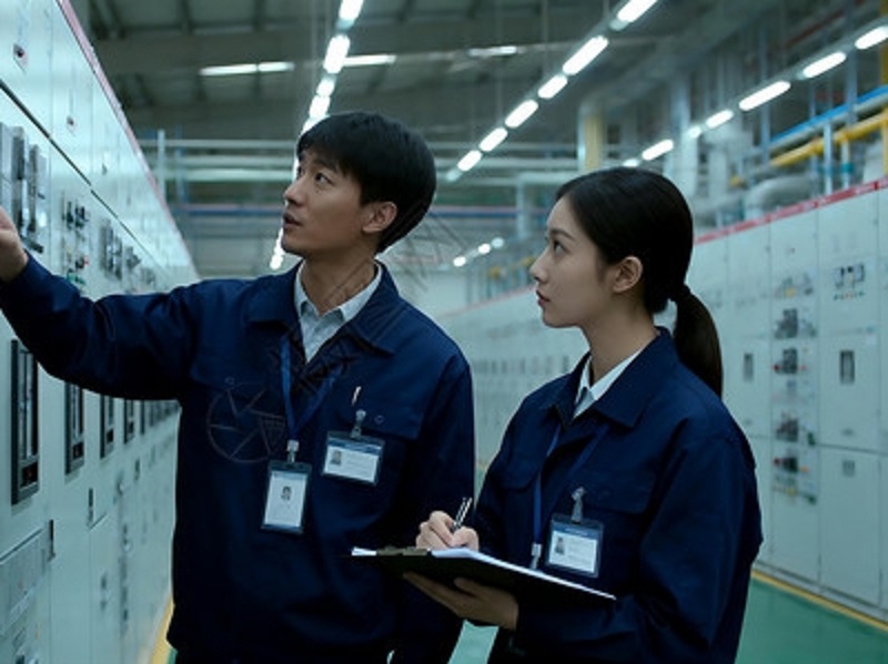
1. GE Mark VIe System Overview
A typical Mark VIe system consists of several functional layers:
| Component |
Main Function |
| Controller |
Executes control logic |
| I/O Modules |
Interface with field devices |
| Network |
Transfers control and process data |
| Operator Station |
Provides process monitoring |
| Engineering Station |
System configuration and maintenance |
| Power Supply |
Provides operating power |
| Field Devices |
Measure and control process conditions |
The basic signal path is:
Field Device → I/O Module → Controller → Control Logic → Output Device
This distributed architecture allows control functions and I/O to be organized according to the requirements of the plant.
2. Controller Installation
The controller is one of the most important components in the control architecture.
Before powering the system, verify:
- Correct controller model
- Correct hardware configuration
- Power connections
- Network connections
- Controller addressing
- Redundancy configuration, if applicable
- Proper cabinet installation
The controller should be installed in an environment that meets the required temperature, humidity and electrical conditions.
3. I/O Module Installation
I/O modules connect the control system to field instrumentation.
Typical I/O signals include:
Analog Inputs
Used for:
- Pressure
- Temperature
- Flow
- Level
- Speed feedback
Analog Outputs
Used for:
- Control valves
- Actuators
- Speed references
Digital Inputs
Used for:
- Switch status
- Motor status
- Valve position
- Equipment alarms
Digital Outputs
Used for:
- Solenoids
- Relays
- Start/stop commands
The physical I/O channel must correspond correctly with the software configuration.
4. Field Wiring
Correct field wiring is essential for reliable operation.
Before commissioning, check:
- Terminal connections
- Cable identification
- Signal polarity
- Shielding
- Cable continuity
- Field-device power
- I/O channel assignment
A well-organized cable schedule should identify every field signal and its corresponding I/O channel.
5. Analog Signal Configuration
Many industrial instruments use 4–20 mA signals.
For example:
| Signal |
Percentage |
| 4 mA |
0% |
| 8 mA |
25% |
| 12 mA |
50% |
| 16 mA |
75% |
| 20 mA |
100% |
The DCS engineering range must match the actual field transmitter range.
If a transmitter is configured for 0–100 bar, the Mark VIe configuration must interpret the corresponding 4–20 mA signal as 0–100 bar.
Incorrect scaling can produce an apparently faulty process value even when the transmitter itself is working correctly.
6. Power Supply and Grounding
Stable power is critical for the control system.
Check:
- Input voltage
- DC output
- Polarity
- Protective devices
- Power distribution
- Grounding
- Redundant power connections where applicable
Poor grounding can cause analog noise, communication problems and unstable signals.
Instrumentation cables should also be routed appropriately and kept away from high-power cables whenever practical.
7. Network Installation
The control network connects controllers, I/O systems, operator stations and engineering equipment.
During installation, verify:
- Network cables
- Network ports
- Device addressing
- Communication status
- Network redundancy
- Power to communication equipment
If communication problems occur, determine whether the problem affects one device or an entire network segment.
8. Control Logic Configuration
The Mark VIe control application may contain:
- Sequential logic
- Interlocks
- Alarm functions
- Analog control
- Equipment control
- Startup sequences
- Shutdown logic
For turbine applications, control strategies may include speed control, temperature monitoring, fuel control, protection and synchronization functions.
All control logic should be tested before the equipment is placed into normal operation.
9. Commissioning Procedure
A practical commissioning sequence is:
Step 1 — Hardware Inspection
Check controllers, I/O modules, power supplies and cabinets.
Step 2 — Wiring Verification
Check field cables and terminals.
Step 3 — Network Test
Verify communication between system components.
Step 4 — I/O Test
Test every input and output.
Step 5 — Logic Test
Verify control logic, interlocks and sequences.
Step 6 — HMI Test
Check process values, alarms and equipment status.
Step 7 — Equipment Startup
Start the equipment under controlled conditions.
10. Troubleshooting Analog Input Problems
If an analog value is missing, check the following sequence:
Field Instrument
↓
Power Supply
↓
Field Wiring
↓
Terminal
↓
I/O Channel
↓
Controller
↓
HMI
This method helps identify where the signal is being lost.
If the value exists but is incorrect, check transmitter calibration, engineering range and software scaling.
11. Troubleshooting Communication Faults
Communication failures may be caused by:
- Damaged network cable
- Incorrect configuration
- Power failure
- Network equipment failure
- Controller communication problems
- I/O communication problems
Start by checking whether the fault is isolated to one component or affects multiple devices.
12. Troubleshooting Controller Faults
When a controller reports a fault, do not immediately replace the hardware.
First check:
- Power supply
- Controller status
- Network communication
- I/O status
- Configuration
- Recent software changes
- Diagnostic information
This approach can prevent unnecessary replacement of expensive control equipment.
13. Preventive Maintenance
A basic maintenance program should include:
- Cabinet inspection
- Power-supply inspection
- I/O diagnostics
- Network checks
- Field-instrument calibration
- Wiring inspection
- Configuration backup
- Alarm review
Critical spare parts should also be identified according to the importance of the equipment and expected replacement time.
14. Common Installation Mistakes
Several problems can be avoided during the installation stage.
Incorrect I/O Assignment
The field cable is connected to the wrong channel.
Incorrect Scaling
The transmitter range does not match the DCS configuration.
Poor Cable Routing
Instrumentation cables are routed too close to high-power equipment.
Incorrect Grounding
Electrical noise affects sensitive signals.
Incomplete Commissioning
Some I/O channels or interlocks are not tested before startup.
15. GE Mark VIe Installation Checklist
Before commissioning, verify:
Conclusion
A successful GE Mark VIe installation depends on correct coordination between controllers, I/O modules, field instrumentation, networks, software and operator interfaces.
The most important commissioning principle is to verify the complete signal path rather than testing individual components in isolation.
When troubleshooting, use a structured approach:
Field Device → Wiring → I/O → Controller → Network → HMI
This method makes it easier to locate wiring problems, configuration errors, communication failures and hardware faults.
For power-generation and turbine applications, special attention should be given to startup sequences, interlocks, protection functions, speed control and equipment status. Proper installation and systematic maintenance can significantly improve the reliability and service life of the overall GE control system.