Introduction
Emerson DeltaV is a distributed control system designed for process automation applications. It can be used to control and monitor equipment, process instruments, valves, motors and production operations across industries such as chemical processing, oil and gas, refining, power and pharmaceuticals.
A successful DeltaV installation requires careful planning of the control architecture, I/O configuration, field wiring, network communication, controller setup and commissioning process.
This guide provides a practical overview of the key installation and commissioning steps.
1. Emerson DeltaV System Overview
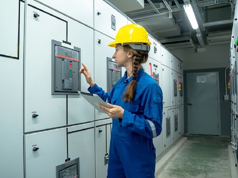
A typical DeltaV system includes:
| Component |
Function |
| Controller |
Executes control strategies |
| I/O Module |
Interfaces with field devices |
| Engineering Station |
System configuration |
| Operator Station |
Process monitoring and control |
| Control Network |
Transfers system data |
| Power Supply |
Provides system power |
| Field Devices |
Measure and control the process |
The basic control path is:
Field Instrument → I/O → Controller → Control Logic → Field Device
2. Controller Installation
The controller executes configured control strategies and communicates with I/O and other system components.
Before powering the controller, verify:
- Correct controller model
- Hardware configuration
- Power connections
- Network connections
- Address configuration
- Redundant architecture, if applicable
The controller should be installed in a suitable cabinet with sufficient ventilation and maintenance access.
3. I/O Module Installation
I/O modules connect field instruments and actuators to the DeltaV system.
Common signal types include:
- Analog input
- Analog output
- Digital input
- Digital output
- Specialized signals
Typical analog inputs are used for pressure, temperature, flow and level measurements.
Digital signals are commonly used for equipment status, valve position and discrete commands.
4. Field Wiring
Field wiring should be checked carefully before system startup.
Verify:
- Cable identification
- Terminal connections
- Signal polarity
- Cable continuity
- Shielding
- Field power
- I/O channel assignment
Every field signal should correspond to the correct channel in the DeltaV configuration.
A detailed I/O list can greatly simplify commissioning and future troubleshooting.
5. Analog Input Configuration
Many process instruments use 4–20 mA signals.
A typical relationship is:
| Signal |
Percentage |
| 4 mA |
0% |
| 8 mA |
25% |
| 12 mA |
50% |
| 16 mA |
75% |
| 20 mA |
100% |
For example, a pressure transmitter configured for 0–10 bar should be correctly scaled in the control system.
Incorrect scaling can cause the operator display to show an incorrect process value even when the transmitter is functioning normally.
6. Digital I/O Configuration
Digital inputs can be used to monitor:
- Pump running status
- Motor status
- Valve open/closed status
- Switches
- Equipment alarms
Digital outputs can be used for:
- Start/stop commands
- Solenoid valves
- Relays
- Discrete actuators
The electrical characteristics of the field device must be compatible with the selected I/O hardware.
7. Power and Grounding
Stable power is essential for reliable DCS operation.
Before startup, check:
- Input power
- DC voltage
- Polarity
- Protective devices
- Ground connections
- Power distribution
Poor grounding can contribute to analog signal noise and communication problems.
Instrumentation wiring should also be separated from high-power wiring whenever practical.
8. DeltaV Network
The control network provides communication between controllers, I/O systems, operator stations and engineering workstations.
During installation, verify:
- Network connections
- Device communication
- Network configuration
- Redundant communication paths
- Network equipment power
If several components lose communication simultaneously, investigate shared network infrastructure before replacing individual modules.
9. Control Strategy Configuration
DeltaV control strategies can include:
- PID loops
- Logic
- Interlocks
- Alarms
- Sequencing
- Calculations
- Equipment control
For example, a temperature-control loop can operate as:
Temperature Transmitter → AI → PID → AO → Control Valve
The controller continuously compares the process value with the desired setpoint and adjusts the output.
10. Alarm Configuration
Alarms provide operators with information about abnormal process conditions.
Common alarm conditions include:
- High pressure
- High temperature
- Low level
- Equipment failure
- Communication failure
- Instrument fault
Alarm limits should be based on actual process requirements.
Excessive alarm settings can result in alarm flooding and make important events harder for operators to identify.
11. Interlocks
Interlocks prevent equipment from operating under unsuitable conditions.
For example:
Low Pump Suction Pressure
↓
Interlock Activated
↓
Pump Start Prevented
Interlocks should be tested during commissioning to ensure that both the permissive and trip conditions operate correctly.
12. Operator Station
The operator station provides access to process information.
Typical displays include:
- Process values
- Equipment status
- Valve positions
- Alarm information
- Trends
- Control-loop information
During commissioning, verify that the displayed information corresponds to the correct field tags.
13. Engineering Workstation
The engineering workstation is used to configure and maintain the DeltaV system.
Typical activities include:
- Hardware configuration
- I/O configuration
- Control strategy development
- Alarm configuration
- Graphics configuration
- Diagnostics
- System backup
Production changes should be controlled and documented.
14. DeltaV Commissioning Procedure
A practical commissioning process can be divided into several stages.
Stage 1 — Hardware Inspection
Check cabinets, controllers, I/O modules and power supplies.
Stage 2 — Wiring Inspection
Verify field cables and terminals.
Stage 3 — Network Test
Confirm communication between system components.
Stage 4 — I/O Test
Test every input and output channel.
Stage 5 — Control Logic Test
Verify control loops, sequences and interlocks.
Stage 6 — Alarm Test
Confirm that alarms appear correctly.
Stage 7 — Process Startup
Start the process under controlled conditions.
15. I/O Loop Checking
Loop checking verifies the complete signal path.
For an analog input:
Field Instrument → Cable → Terminal → I/O Module → Controller → Operator Station
For an output:
Controller → I/O Module → Terminal → Actuator
Testing the entire loop is more reliable than checking only the software indication.
16. Troubleshooting Analog Input Problems
If an analog value is missing, check:
- Field instrument power
- Instrument output
- Cable continuity
- Terminal connection
- I/O channel
- Controller status
- Configuration
- Operator display
If the signal is present but the value is incorrect, check scaling and transmitter range.
17. Troubleshooting Unstable Signals
A fluctuating analog value can be caused by:
- Instrument problems
- Loose wiring
- Electrical interference
- Poor grounding
- Shielding problems
- Process fluctuations
Compare the DCS value with the actual field measurement before replacing hardware.
18. Troubleshooting Communication Problems
When communication is lost, check:
- Network cables
- Network equipment
- Power
- Controller status
- I/O communication
- Configuration
Determine whether the fault affects one component or multiple components.
A single-device failure may indicate a local problem, while multiple simultaneous failures may indicate a network or power issue.
19. Troubleshooting Controller Problems
When a controller reports a fault:
- Check power
- Check controller diagnostics
- Check network communication
- Check I/O status
- Review recent configuration changes
- Check system alarms
Hardware replacement should normally be considered only after basic power, communication and configuration checks have been completed.
20. Preventive Maintenance
A practical DeltaV maintenance program should include:
Hardware
- Cabinet inspection
- Power-supply checks
- Module inspection
Field Devices
- Instrument calibration
- Wiring inspection
- Sensor verification
Network
- Communication checks
- Cable inspection
Software
- Configuration backups
- Change management
- System documentation
21. Configuration Backup
Control-system configuration should be backed up regularly.
Important information can include:
- Controller configuration
- I/O configuration
- Control strategies
- Alarm settings
- Operator graphics
- System settings
A current backup can significantly reduce recovery time after a hardware or configuration problem.
22. Common Installation Errors
Incorrect I/O Assignment
The physical field cable is connected to a different channel than the configured channel.
Incorrect Scaling
The transmitter range does not match the DCS range.
Poor Grounding
Electrical interference affects process measurements.
Incorrect Cable Routing
Instrumentation cables are routed too close to high-power cables.
Incomplete Loop Testing
Some field signals are not verified before startup.
23. Recommended Troubleshooting Method
When a process value appears abnormal, follow the signal path:
Field Device
↓
Wiring
↓
I/O Module
↓
Controller
↓
Control Network
↓
Operator Station
This approach helps determine whether the problem is caused by field instrumentation, wiring, I/O hardware, software configuration, communication or visualization.
24. DeltaV Installation Checklist
Before final commissioning, verify:
Conclusion
A reliable Emerson DeltaV installation requires coordination between field instrumentation, I/O modules, controllers, networks, control strategies and operator stations.
The most important commissioning task is to verify the complete signal path from the field device to the operator interface and back to the final control element.
For troubleshooting, technicians should avoid replacing hardware immediately. Instead, they should systematically check power, wiring, I/O, configuration, controller operation, communication and HMI information.
Proper installation, accurate configuration, comprehensive loop checking and regular maintenance can improve system reliability and make future fault diagnosis significantly faster.