

ProductPRODUCT
Featured products
Contact Us
- GE
- IS210JPDHG1A
- DIN Rail Module
- USA
- 260 × 120 × 65 mm
- 0.85 kg
- Xiamen, China
- New & In Stock
- T/T, PayPal, Western Union
- 1 Year
- 1-3 Working Days
- DHL, UPS, TNT, FedEx and EMS.
- 24-Hour Service
- COO
- 3
Our advantage

Global Logistics
We have a 10-year logistics and express cooperation agreement, so our products can be shipped to any place in the world.

Brand new and original
Our products are imported in bulk from the place of origin. Because of the cooperative relationship, our products are all original and 100% new.

24-hour service
We provide 7*24 hours service to our customers. We will be there whenever you need us.

Price advantage
All our products are priced very favorably because we have our own warehouse and supply.
| Company Information | |||
| [email protected] | |||
| Mobile | +8615980777398 | ||
| +8615980777398 | |||
| 15980777398 |
Product Overview
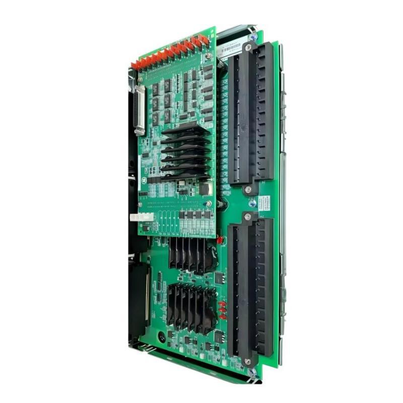
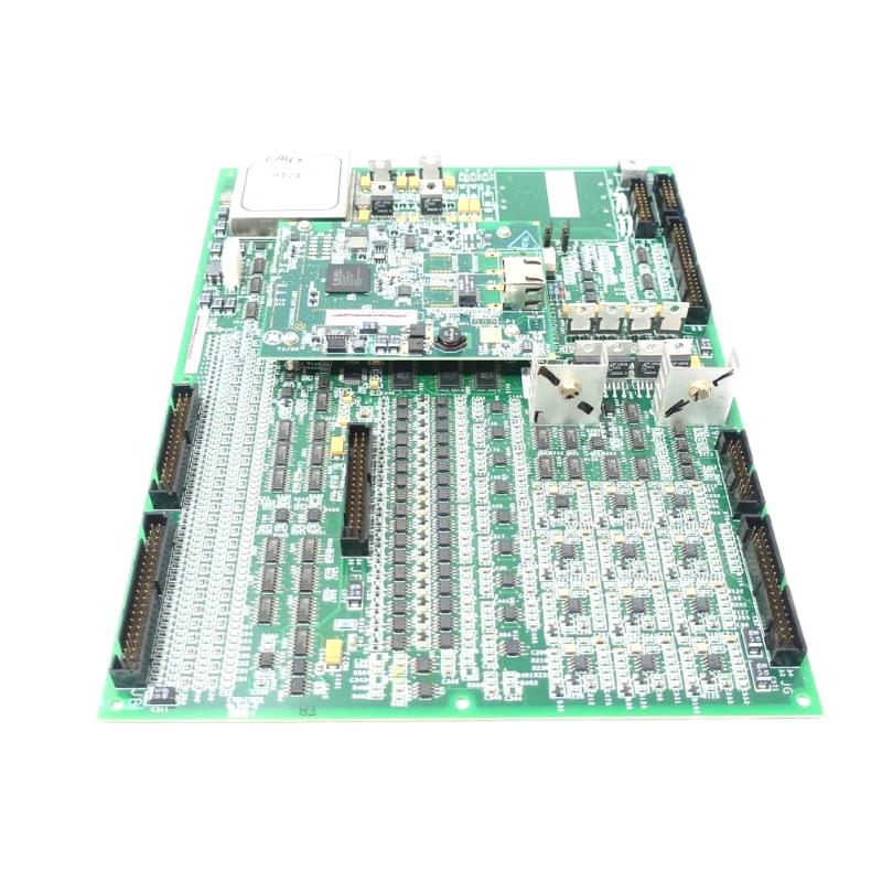
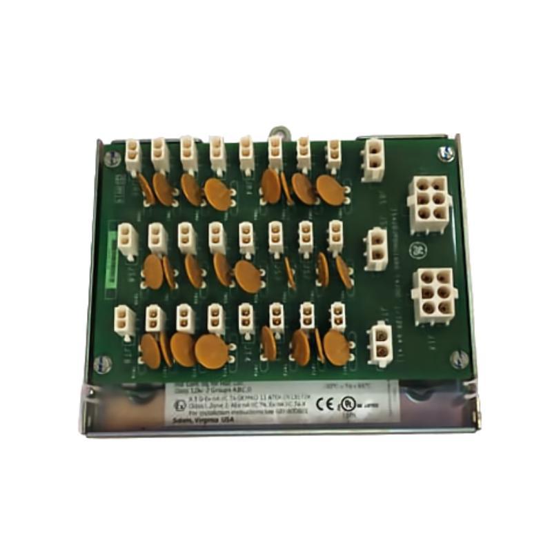
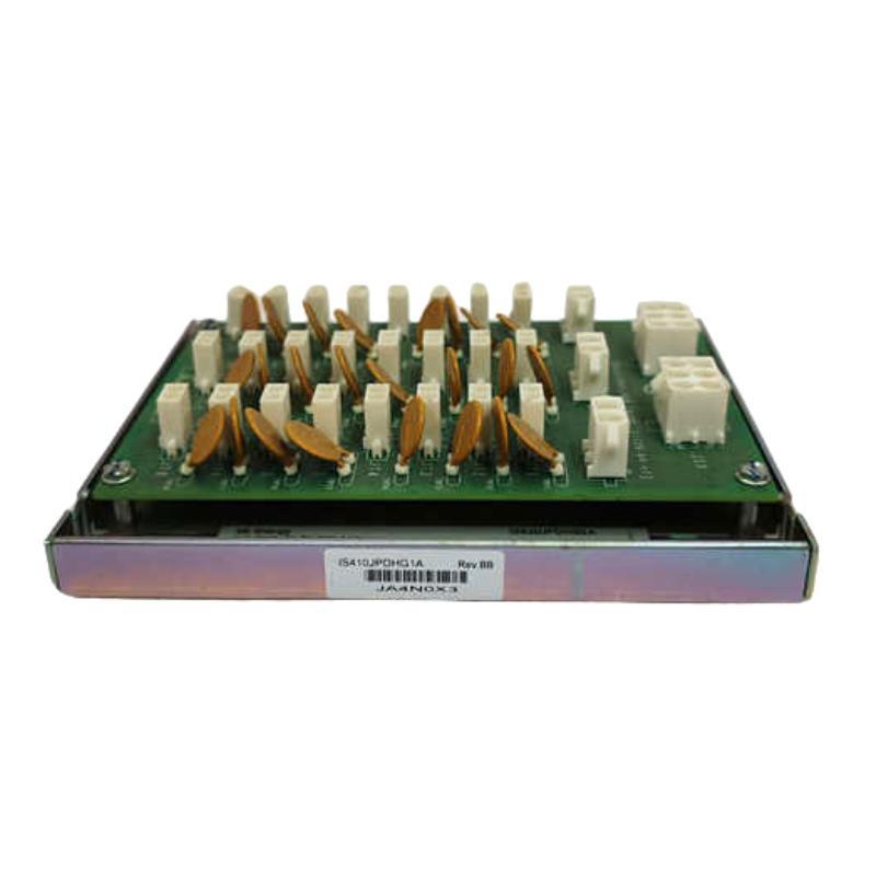
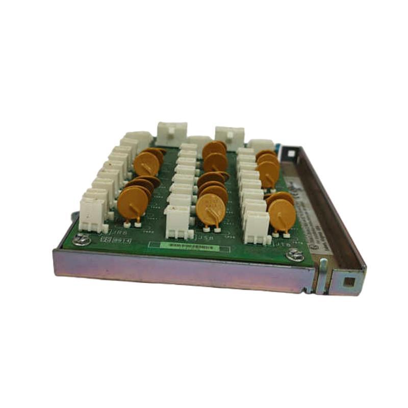
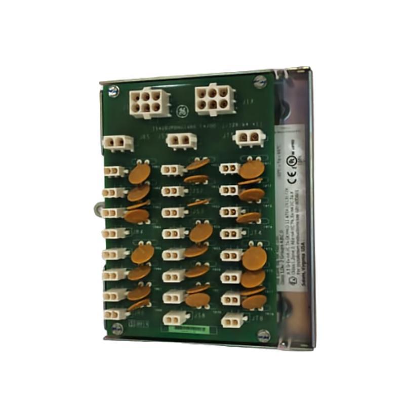
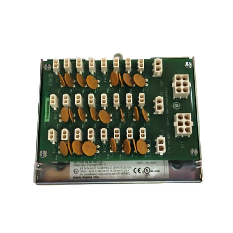
The GE IS210JPDHG1A DIN Rail Module is an industrial automation component designed for installation within a compatible GE control and instrumentation system. DIN rail-mounted assemblies are widely used in industrial cabinets because they provide a practical method for organizing electronic modules, interface devices, terminal assemblies, and other control-system components.
The IS210JPDHG1A belongs to the GE IS210 family of industrial electronic assemblies. Its DIN rail mounting format allows it to be incorporated into structured control cabinets where equipment needs to be securely installed while maintaining convenient access for wiring, inspection, maintenance, and replacement.
The supplied physical dimensions of the GE IS210JPDHG1A are 260 × 120 × 65 mm, with a listed weight of 0.85 kg. Its relatively compact construction allows it to occupy considerably less cabinet space than large control assemblies while still providing a dedicated interface or control-system function.
The exact electrical function, terminal arrangement, signal characteristics, and system compatibility of the IS210JPDHG1A should be verified against the applicable GE system configuration before installation. The complete model designation should always be used when purchasing or replacing the module.
Technical Specifications
| Parameter | Specification |
|---|---|
| Manufacturer | General Electric (GE) |
| Model | IS210JPDHG1A |
| Product Type | DIN Rail Module |
| Product Family | GE IS210 Series |
| Mounting Type | DIN Rail |
| Application | Industrial Automation and Control |
| Primary Role | Control-system interface / industrial electronic module |
| Dimensions | 260 × 120 × 65 mm |
| Weight | 0.85 kg |
| Installation | Industrial Control Cabinet |
| System Compatibility | Compatible GE control-system architecture |
The physical dimensions and weight above are based on the specifications supplied for this product. Exact electrical specifications such as input/output characteristics, operating voltage, terminal assignments, communication interfaces, isolation, and protection ratings should be confirmed for the specific hardware configuration.
What Is the GE IS210JPDHG1A?
The GE IS210JPDHG1A is a DIN rail-mounted industrial module intended for integration into compatible GE automation and control equipment.
DIN rail modules are commonly used where industrial electronic equipment needs to be arranged in an organized cabinet environment. Instead of requiring a large dedicated mounting structure, DIN rail equipment can be installed on a standardized rail system together with other control components.
A typical cabinet architecture may be represented as:
Power Supply → Interface Modules → Controller → I/O → Field Devices → Industrial Process
The exact position of the IS210JPDHG1A within this architecture depends on the host equipment and system design.
Because industrial control modules can perform different functions even when their physical appearance is similar, the complete IS210JPDHG1A identification should be checked before installation or replacement.
DIN Rail Mounting and Mechanical Design
One of the important characteristics of the GE IS210JPDHG1A is its DIN rail mounting format.
DIN rail installation provides several practical benefits in industrial cabinets.
Organized Cabinet Layout
Modules can be arranged along a common mounting rail, helping engineers create a structured control-panel layout.
Efficient Space Utilization
The compact dimensions of 260 × 120 × 65 mm allow the module to be incorporated into equipment cabinets where available space must be managed carefully.
Simplified Maintenance
A standardized mounting arrangement can make inspection and replacement easier when adequate service clearance is provided.
Modular System Construction
DIN rail components can be installed alongside compatible terminal blocks, interface devices, power equipment, and other control-system hardware.
Function Within an Industrial Control System
The IS210JPDHG1A should be considered as one component within a larger automation architecture.
Industrial control systems generally contain several functional levels:
| System Layer | Typical Function |
|---|---|
| Power System | Provides electrical power |
| Controller | Executes control logic |
| Interface Modules | Connect system components |
| I/O System | Processes field signals |
| Communication Network | Transfers control data |
| Field Devices | Measure process conditions |
| Actuators | Perform physical control actions |
| Industrial Process | Performs the required operation |
A DIN rail module can provide an interface between different layers depending on its specific system function.
This makes correct module identification and system integration especially important during installation and maintenance.
Industrial Applications
Industrial Automation Cabinets
The GE IS210JPDHG1A can be incorporated into industrial control cabinets where compact DIN rail-mounted equipment is required.
Typical cabinet environments may contain:
- Controllers
- Interface modules
- Terminal blocks
- Power supplies
- Communication equipment
- Signal-conditioning devices
- Protection devices
- Industrial networking components
Process Control
Industrial process-control systems frequently use modular cabinet architectures. DIN rail components can help organize the interface between field instrumentation and the control system.
Manufacturing Equipment
Automated production equipment often requires compact control assemblies that can be mounted together in a structured cabinet.
Utility and Infrastructure Systems
Water treatment, energy, building automation, and other infrastructure systems may use DIN rail-mounted electronic components as part of distributed control panels.
Industrial Instrumentation
Instrumentation cabinets can contain numerous signal and interface components. Compact DIN rail construction helps simplify equipment arrangement and maintenance.
System Integration
The GE IS210JPDHG1A should be installed according to the architecture of the compatible GE control system.
A representative industrial installation may include:
Power Supply → IS210JPDHG1A → Control Electronics → I/O → Field Equipment
Depending on the system, other equipment may include:
- GE control processors
- I/O boards
- Terminal boards
- Interface modules
- Communication assemblies
- Power supplies
- Signal-conditioning equipment
- Operator interfaces
- Industrial network equipment
The exact connection arrangement should be confirmed from the system documentation and existing installation.
Installation Guide
1. Verify the Product Identification
Before installation, confirm that the module is:
GE IS210JPDHG1A
Check the complete part number and hardware markings against the equipment documentation.
2. Inspect the Module
Check the module for:
- Physical damage
- Cracked housing
- Damaged connectors
- Bent mounting hardware
- Contamination
- Signs of overheating
Do not install a visibly damaged component.
3. Prepare the DIN Rail
Ensure that the mounting rail is correctly installed and securely attached to the cabinet structure.
The rail should be capable of supporting the module and other equipment installed on the same mounting structure.
4. Install the Module
Position the IS210JPDHG1A correctly on the DIN rail and secure it according to the applicable mounting arrangement.
5. Connect Wiring
Connect the required wiring according to the approved electrical documentation.
Do not assume terminal functions solely from the physical appearance of the module.
6. Check Grounding
Verify the required grounding and bonding arrangement for the complete control cabinet.
7. Inspect Cable Routing
Ensure cables are routed cleanly and that power wiring is appropriately separated from sensitive signal wiring where required.
8. Perform Final Inspection
Before energizing the system, verify:
- Module identification
- Mechanical mounting
- Wiring
- Connectors
- Grounding
- Cable routing
- Cabinet clearance
Cabinet Layout and Thermal Management
Although the IS210JPDHG1A weighs only 0.85 kg, its installation location should still be selected carefully.
The supplied physical dimensions are:
260 × 120 × 65 mm
Cabinet planning should allow sufficient space for:
- Module installation
- Wiring
- Connector access
- Ventilation
- Inspection
- Maintenance
- Replacement
Avoid placing the module where nearby equipment can obstruct airflow or prevent technicians from accessing the wiring.
The thermal conditions of the entire cabinet should also be considered. Heat generated by neighboring power supplies, drives, relays, or other electronic devices can influence the operating environment of the module.
Electrical Integration Considerations
The exact electrical characteristics of the IS210JPDHG1A should be verified against the applicable GE system documentation.
Before commissioning, engineers should confirm:
- Supply requirements
- Terminal assignments
- Signal type
- Connected devices
- Grounding
- Circuit protection
- Cable specifications
- System configuration
- Compatible hardware
The model number should not be used alone to infer electrical ratings that have not been confirmed.
This is particularly important when replacing an existing module because visually similar industrial boards can have different electrical functions.
Commissioning Procedure
A structured commissioning process can help verify correct installation.
Step 1 — Confirm Hardware
Check the complete IS210JPDHG1A identification.
Step 2 — Inspect Mechanical Installation
Verify that the module is securely mounted on the DIN rail.
Step 3 — Check Connections
Inspect all relevant terminals and connectors.
Step 4 — Verify Cabinet Conditions
Check temperature, ventilation, cleanliness, and physical clearance.
Step 5 — Confirm System Configuration
Verify that the module is installed in the intended position within the GE control architecture.
Step 6 — Energize the System
Apply power according to the approved commissioning procedure.
Step 7 — Check Status Information
Review available system indicators and diagnostics.
Step 8 — Test Connected Functions
Verify the operation of the associated control, interface, or I/O functions.
Step 9 — Monitor Operation
Observe the system under normal operating conditions and confirm stable performance.
Troubleshooting the GE IS210JPDHG1A
Troubleshooting should begin with the complete system rather than assuming that the DIN rail module itself is defective.
Module Does Not Operate
Possible causes include:
- Incorrect installation
- Missing power
- Loose wiring
- Incorrect terminal connection
- Connector problems
- System configuration error
- Fault in an associated component
Check the power and wiring before replacing the module.
Intermittent Operation
Intermittent problems can be associated with:
- Loose connections
- Damaged cables
- Vibration
- Poor contact
- Temperature changes
- Electrical interference
- Associated equipment faults
Inspect the module and its surrounding wiring while monitoring system behavior.
Unexpected System Faults
If the control system reports an unexpected fault, investigate:
- Module status
- Power supply
- Wiring
- Connectors
- Associated I/O
- Communication path
- Controller diagnostics
- System configuration
This approach reduces the possibility of replacing a healthy module unnecessarily.
Communication or Signal Problems
If the module participates in a signal or interface path, inspect the complete path from the field device to the controller.
A fault can originate from:
- Field wiring
- Terminal connection
- Interface hardware
- Power supply
- Controller configuration
- Communication equipment
Preventive Maintenance
Regular inspection helps maintain the reliability of DIN rail-mounted control equipment.
Inspect Mounting
Verify that the module remains securely attached to the DIN rail.
Check Connections
Inspect terminals, connectors, and cables for looseness or physical deterioration.
Maintain Cabinet Cleanliness
Dust and contamination should be controlled because excessive buildup can interfere with cooling and maintenance.
Inspect for Thermal Stress
Look for discoloration, damaged insulation, or other signs of excessive temperature.
Monitor System Diagnostics
Recurring alarms or intermittent faults should be investigated rather than repeatedly reset.
Maintain Documentation
Record the installed module identification and cabinet location to simplify future maintenance and replacement.
Replacement Considerations
When replacing the GE IS210JPDHG1A, the complete part number should be checked carefully.
Important replacement information includes:
| Item | Purpose |
|---|---|
| Full Model Number | Confirms exact module |
| Hardware Revision | Helps verify compatibility |
| DIN Rail Arrangement | Confirms mechanical installation |
| Dimensions | Confirms cabinet space |
| Wiring | Confirms connection arrangement |
| Host System | Confirms application |
| Associated Modules | Confirms system integration |
| Installation Location | Supports maintenance planning |
The supplied dimensions are 260 × 120 × 65 mm, and the listed weight is 0.85 kg.
A different IS210 module should not automatically be treated as a direct replacement simply because it uses a similar housing or mounting method.
Physical Dimensions and Weight
The supplied mechanical specifications are:
| Physical Parameter | Value |
|---|---|
| Length | 260 mm |
| Width | 120 mm |
| Height / Depth | 65 mm |
| Overall Dimensions | 260 × 120 × 65 mm |
| Weight | 0.85 kg |
| Mounting Type | DIN Rail |
These specifications are useful for:
- Cabinet layout
- DIN rail planning
- Equipment inventory
- Transportation
- Storage
- Replacement preparation
- Maintenance planning
The relatively low weight makes handling straightforward compared with large industrial power modules, while the 260 × 120 × 65 mm envelope should still be considered when planning cabinet density.
Engineering Best Practices
Use the Complete Part Number
Always identify the module as GE IS210JPDHG1A rather than relying on a general product description.
Confirm Compatibility
Verify the module against the host GE control system before installation.
Keep Wiring Organized
Structured wiring improves troubleshooting and reduces the risk of incorrect connections.
Provide Service Clearance
Leave sufficient space around the module for inspection and replacement.
Separate Sensitive Wiring
Where applicable, maintain appropriate separation between high-power wiring and low-level signal or communication wiring.
Maintain Accurate Documentation
Record the module location, wiring arrangement, hardware identification, and maintenance history.
Related GE Industrial Automation Components
A GE industrial control cabinet may contain multiple types of electronic assemblies around a DIN rail module.
| Component Type | Typical Role |
|---|---|
| GE Control Processor | Executes control logic |
| I/O Board | Interfaces with field signals |
| Terminal Board | Provides field wiring interface |
| Interface Module | Connects control-system components |
| Power Supply | Provides electrical power |
| Communication Module | Transfers control data |
| Signal-Conditioning Module | Processes field signals |
| Relay Interface | Interfaces discrete control circuits |
| Operator Interface | Provides monitoring and control |
The exact combination depends on the equipment architecture.
Key Advantages
The GE IS210JPDHG1A DIN Rail Module provides several practical characteristics for industrial control installations:
- DIN rail mounting format
- Compact industrial construction
- Suitable for structured control cabinets
- 260 × 120 × 65 mm listed dimensions
- 0.85 kg listed weight
- Convenient cabinet integration
- Suitable for modular industrial automation architectures
- Supports organized installation and maintenance
- Compatible with appropriate GE control-system configurations
Technical FAQs
What is the GE IS210JPDHG1A?
The GE IS210JPDHG1A is a DIN Rail Module designed for integration into a compatible GE industrial automation and control system.
What type of mounting does the IS210JPDHG1A use?
The product is identified as a DIN Rail Module, allowing it to be installed on a compatible DIN rail inside an industrial control cabinet.
What are the dimensions of the GE IS210JPDHG1A?
The supplied dimensions are 260 × 120 × 65 mm.
How much does the IS210JPDHG1A weigh?
The listed weight is 0.85 kg.
Where can the IS210JPDHG1A be used?
It can be integrated into compatible GE industrial control, instrumentation, and automation cabinets. The exact application depends on the host system.
Should the electrical specifications be inferred from the model number?
No. Exact electrical characteristics, terminal functions, signal specifications, and compatibility should be confirmed against the applicable system documentation.
Can another GE IS210 module replace the IS210JPDHG1A?
Not automatically. The complete model number, hardware revision, electrical interface, mechanical arrangement, and host-system requirements should be verified before replacement.
What should be checked if the module appears to be faulty?
Check power, wiring, connectors, DIN rail mounting, associated equipment, controller diagnostics, and system configuration before concluding that the module itself has failed.
Conclusion
The GE IS210JPDHG1A DIN Rail Module is a compact industrial automation component intended for installation within a compatible GE control-system architecture. Its DIN rail mounting format makes it suitable for structured industrial cabinets where modular installation, organized wiring, and convenient maintenance are important.
The supplied physical specifications are 260 × 120 × 65 mm, with a listed weight of 0.85 kg. These dimensions should be considered during cabinet layout, DIN rail planning, wiring, ventilation, and service-access design.
For installation or replacement, the complete GE IS210JPDHG1A designation should be verified carefully. The module should be matched to the correct host system, wiring arrangement, associated equipment, and electrical configuration rather than selected solely on physical appearance.
With appropriate installation, organized wiring, correct system integration, and regular maintenance, the GE IS210JPDHG1A can serve as a practical DIN rail-mounted component within compatible GE industrial automation and control environments.