

ProductPRODUCT
Featured products
Contact Us
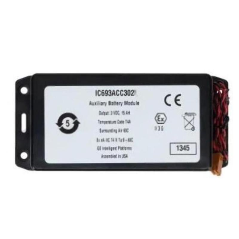
- GE
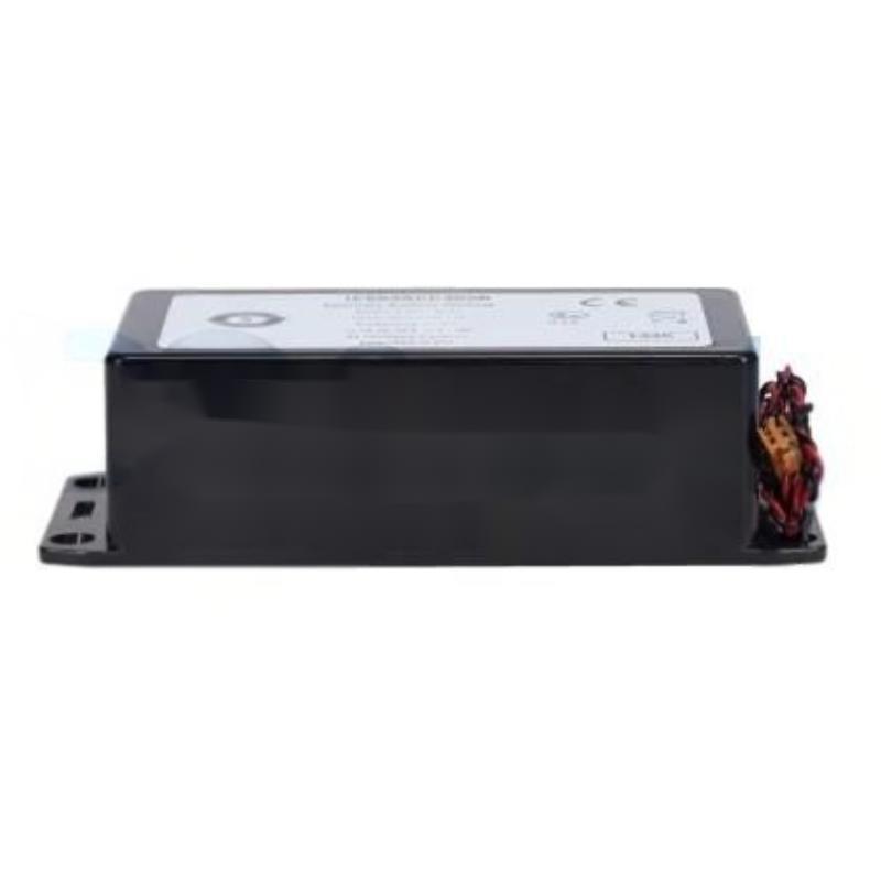
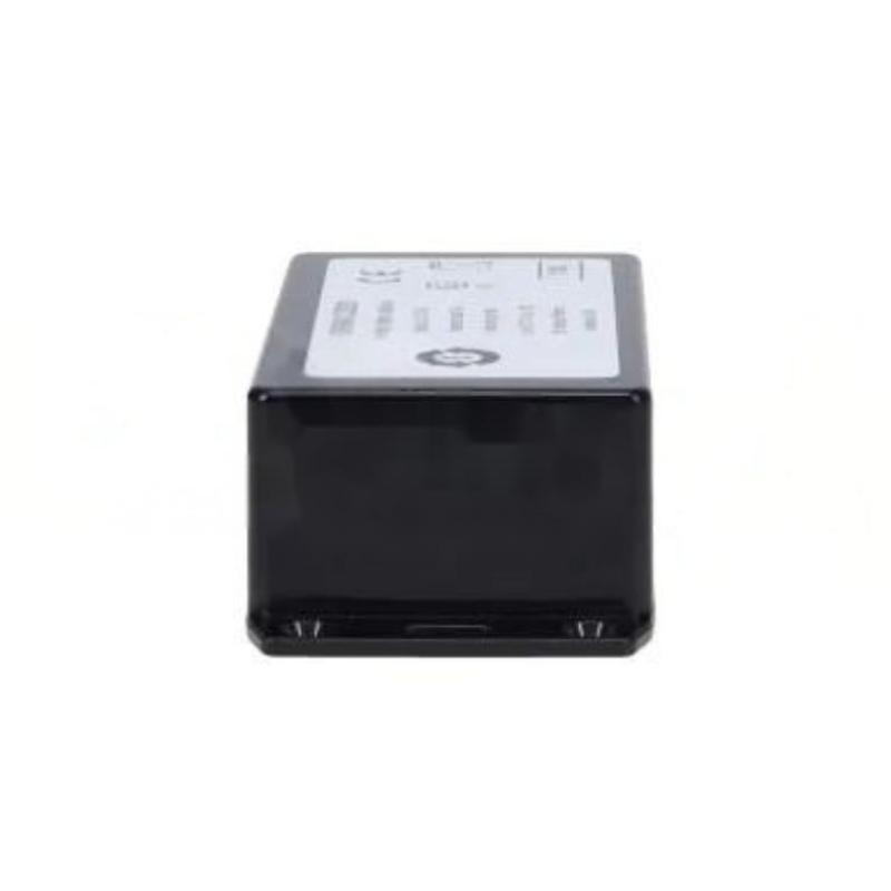
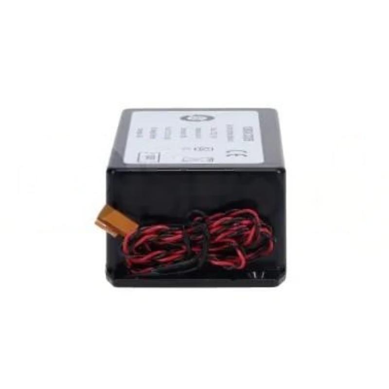
- GE IC695ACC302
- Auxiliary Smart Battery Module
- USA
- 145.1 x 65 x 39.9 mm
- 0.224 kg
- Xiamen, China
- New & In Stock
- T/T, PayPal, Western Union
- 1 Year
- 1-3 Working Days
- DHL, UPS, TNT, FedEx and EMS.
- 24-Hour Service
- COO
- 5
Our advantage

Global Logistics
We have a 10-year logistics and express cooperation agreement, so our products can be shipped to any place in the world.

Brand new and original
Our products are imported in bulk from the place of origin. Because of the cooperative relationship, our products are all original and 100% new.

24-hour service
We provide 7*24 hours service to our customers. We will be there whenever you need us.

Price advantage
All our products are priced very favorably because we have our own warehouse and supply.
| Company Information | |||
| [email protected] | |||
| Mobile | +8615980777398 | ||
| +8615980777398 | |||
| 15980777398 |
Product Overview
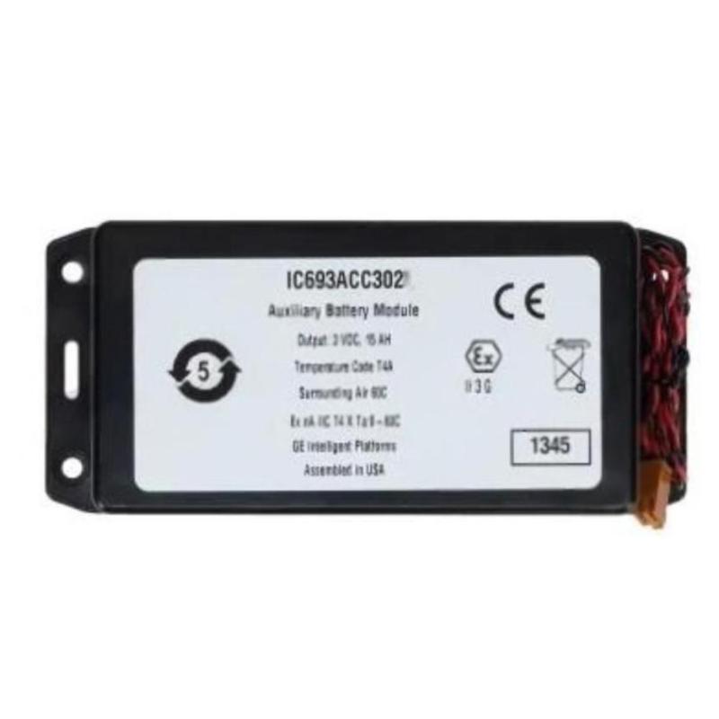
The GE IC695ACC302 Auxiliary Smart Battery Module is a specialized battery-related component used within compatible GE industrial automation and control systems. Its primary purpose is to provide an auxiliary battery function for system memory or other battery-supported control-system requirements, depending on the overall hardware configuration.
Battery modules are particularly important in PLC environments where certain system data, memory functions, clock functions, or retained information may depend on a reliable backup power source. A battery module therefore requires different maintenance considerations from standard I/O modules.
The specified dimensions of the GE IC695ACC302 are 145.1 × 65 × 39.9 mm, with a specified weight of 0.224 kg.
Because battery-backed systems can be affected by battery condition, connection integrity, installation orientation, environmental conditions, and maintenance intervals, technicians should treat the IC695ACC302 as a maintenance-critical component.
Product Identification
| Parameter | Specification |
|---|---|
| Manufacturer | GE |
| Series | IC695 |
| Model | IC695ACC302 |
| Product Type | Auxiliary Smart Battery Module |
| Main Function | Auxiliary Battery Support |
| Application | Industrial PLC / Automation System |
| Dimensions | 145.1 × 65 × 39.9 mm |
| Weight | 0.224 kg |
| Installation | Compatible Control System / Cabinet |
| System Role | Battery Backup / Retention Support |
| Maintenance Focus | Battery Condition and Connection Integrity |
Technical Specifications
| Technical Item | Specification |
|---|---|
| Manufacturer | GE |
| Model | IC695ACC302 |
| Product Category | Auxiliary Smart Battery Module |
| Function | Auxiliary Battery Support |
| Dimensions | 145.1 × 65 × 39.9 mm |
| Weight | 0.224 kg |
| Application | Industrial Automation |
| Installation Environment | Control Cabinet |
| System Role | Battery-Related Support Function |
| Maintenance | Battery and Connection Inspection |
| Configuration | Dependent on Compatible Control System |
The exact battery chemistry, nominal voltage, capacity, service life, connector arrangement, supported controller combinations, and battery-monitoring behavior should be verified against the applicable system documentation before installation or replacement.
What Is the GE IC695ACC302?
The IC695ACC302 is an Auxiliary Smart Battery Module intended for use as part of a compatible GE industrial control system.
A simplified architecture can be represented as:
IC695ACC302
↓
Battery-Supported Control Function
↓
PLC / Control System
↓
Retained Data / System Function
The actual function supported by the battery depends on the hardware architecture in which the module is installed.
Why Auxiliary Battery Modules Are Important
Industrial PLC systems may need battery-backed functionality to preserve selected information or maintain system functions when normal control power is unavailable.
A reliable auxiliary battery system can help prevent problems associated with:
- Battery depletion
- Unexpected memory loss
- Clock or retention issues
- Battery-related diagnostic alarms
- Unplanned maintenance interruptions
The exact functions supported should always be confirmed for the installed PLC configuration.
Installation Guide
1. Verify the Model
Confirm the module identification:
GE IC695ACC302
Check the model number against the system documentation before installation.
Do not replace a battery module solely because another product appears physically similar.
2. Inspect the Module
Before installation, inspect the IC695ACC302 for:
- Damaged housing
- Cracks
- Deformation
- Connector damage
- Corrosion
- Leakage
- Abnormal swelling
- Signs of overheating
If the battery component shows physical damage or leakage, do not place it into service.
3. Check the Dimensions
The specified dimensions are:
145.1 × 65 × 39.9 mm
Ensure adequate space for:
- Installation
- Connector access
- Cable routing
- Inspection
- Battery replacement
- Ventilation
Do not compress the module between adjacent equipment.
4. Check the Weight
The specified weight is:
0.224 kg
Ensure that the mounting arrangement can safely support the module and any associated wiring.
5. Review the System Configuration
Before installation, identify:
- Compatible controller
- Associated rack or control hardware
- Battery connection
- Battery-monitoring arrangement
- Retention requirements
- Existing battery condition
This prevents accidental installation into an incompatible system.
6. Prepare for Installation
Before replacing or installing the module:
- Place the machine in a safe state.
- Review the control-system shutdown procedure.
- Determine whether the system requires continuous battery support during replacement.
- Follow the approved battery replacement procedure.
- Protect against accidental short circuits.
- Use appropriate ESD precautions where required.
Battery replacement procedures should be planned carefully when retained data or system settings are important.
7. Handle the Battery Correctly
Avoid:
- Short-circuiting battery terminals
- Crushing the housing
- Dropping the module
- Exposing the battery to excessive heat
- Opening the battery enclosure
- Using an incorrect replacement battery
Battery modules should be handled according to the applicable industrial battery safety procedures.
8. Connect the Module
Install the IC695ACC302 in the correct system location and connect it according to the approved configuration.
Verify:
- Correct connector
- Correct polarity where applicable
- Secure connection
- Proper cable routing
- No excessive mechanical strain
9. Secure the Module
Confirm that the module is mechanically stable.
A loose installation can result in:
- Intermittent battery connection
- Diagnostic alarms
- Unexpected system behavior
- Premature connector wear
Battery Replacement Considerations
Battery replacement requires more attention than ordinary module replacement because removing the battery source may affect retained system functions.
Before removing an existing battery:
- Determine what functions depend on the battery.
- Check current battery status.
- Back up critical PLC data.
- Review the controller’s battery replacement procedure.
- Prepare the replacement battery in advance.
- Minimize unnecessary power interruption.
Never remove a battery simply to test whether the system can operate without it.
Commissioning Procedure
Step 1 – Visual Inspection
Check:
- Housing condition
- Connector condition
- Mounting
- Wiring
- Battery identification
Step 2 – Verify Connection
Confirm that the IC695ACC302 is properly connected.
Inspect the connector for:
- Loose engagement
- Contamination
- Mechanical damage
- Incorrect orientation
Step 3 – Power Up the System
Restore system power according to the approved startup procedure.
Observe the controller and system diagnostics.
Step 4 – Check Battery Status
If the compatible control system provides battery monitoring, verify the reported status.
Look for indications such as:
- Normal
- Battery low
- Battery missing
- Battery fault
- Replacement required
The exact diagnostic terminology depends on the controller and system configuration.
Step 5 – Verify Retention Functions
Confirm that the system’s battery-supported functions operate normally.
Depending on the architecture, this may involve checking:
- Retained data
- System status
- Clock-related functions
- Battery diagnostics
Step 6 – Check for Alarms
Review controller diagnostics for:
- Battery alarms
- Hardware faults
- Connection errors
- Configuration problems
Any persistent battery alarm should be investigated before returning the system to normal production.
Troubleshooting Guide
Fault 1 – Battery Module Is Not Detected
Possible Causes
- Loose connector
- Incorrect installation
- Wiring problem
- Incompatible hardware
- Battery module fault
- Controller configuration issue
Diagnostic Sequence
Check:
Module → Connector → Wiring → Controller → Configuration
Fault 2 – Low-Battery Alarm
A low-battery alarm may indicate:
- Battery approaching end of service life
- Battery capacity degradation
- Poor connection
- Battery-monitoring problem
Do not ignore a low-battery indication.
Plan replacement according to the approved maintenance procedure.
Fault 3 – Battery Status Changes Intermittently
Possible causes include:
- Loose connector
- Vibration
- Poor contact
- Damaged wiring
- Battery degradation
- Environmental conditions
Inspect the physical connection before replacing the module.
Fault 4 – Battery Alarm Remains After Replacement
Possible causes include:
- Replacement not correctly connected
- Incorrect battery type
- Controller has not recognized the new battery
- Battery-monitoring circuit problem
- Configuration issue
- Connector problem
Verify the complete replacement procedure.
Fault 5 – Retained Data Is Lost
Possible causes include:
- Battery depletion
- Battery disconnected too long
- Incorrect replacement procedure
- Memory-retention problem
- Control-system fault
First determine whether the lost data was actually battery-supported.
Fault 6 – Controller Reports Battery Failure
Possible causes include:
- Battery depleted
- Battery connection problem
- Incorrect battery installation
- Damaged battery
- Battery monitoring fault
Review the controller diagnostic information before concluding that the battery module itself has failed.
Fault 7 – Module Becomes Unusually Warm
Possible causes may include:
- Electrical fault
- Short circuit
- Incorrect connection
- Environmental overheating
- Damaged battery
A battery module showing abnormal heating should be isolated and investigated immediately using appropriate safety procedures.
Fault 8 – Visible Battery Leakage or Swelling
Do not continue normal operation with a visibly damaged battery.
Possible causes include:
- Battery degradation
- Excessive temperature
- Physical damage
- Internal battery failure
Follow the applicable battery handling and disposal procedures.
Fault 9 – Battery Replacement Interval Is Too Short
Possible causes include:
- High operating temperature
- Incorrect battery type
- Continuous high battery load
- Aging hardware
- Abnormal battery drain
Investigate the system’s battery consumption and environmental conditions.
Fault 10 – System Clock or Retained Function Is Incorrect
Potential causes include:
- Weak battery
- Battery disconnected
- Incorrect system configuration
- Controller fault
- Retention function problem
Check battery status first, then investigate the affected system function.
Fault Diagnosis Flow
A structured diagnostic sequence is:
Battery Module
↓
Connector
↓
Battery Monitoring
↓
Controller
↓
Retained Function
↓
PLC Application
This helps separate a physical battery problem from a controller or application-level problem.
Preventive Maintenance
Battery Condition
Periodically inspect the battery status through the applicable controller diagnostics.
Watch for:
- Low-battery warnings
- Battery replacement alarms
- Intermittent battery status
- Abnormal system retention behavior
Physical Inspection
Inspect the module for:
- Cracks
- Swelling
- Leakage
- Corrosion
- Connector damage
- Discoloration
Environmental Monitoring
Battery performance can be affected by environmental conditions.
Maintain appropriate:
- Temperature
- Humidity
- Ventilation
- Cabinet cleanliness
Avoid unnecessary exposure to excessive heat.
Backup Management
Battery-backed systems should not rely exclusively on the physical battery for data security.
Maintain appropriate backups of:
- PLC programs
- Hardware configurations
- System parameters
- Application settings
- Critical machine data
A battery maintains certain supported functions; it is not a substitute for proper data backup.
Maintenance Table
| Maintenance Area | Recommended Action |
|---|---|
| Battery Status | Monitor diagnostic condition |
| Housing | Inspect for physical damage |
| Connector | Check engagement and condition |
| Temperature | Monitor cabinet environment |
| Leakage | Inspect for abnormal battery condition |
| Retention | Verify supported functions |
| PLC Program | Maintain current backup |
| Configuration | Maintain configuration backup |
| Alarms | Investigate battery warnings |
| Replacement | Follow approved battery procedure |
Industrial Applications
PLC Control Systems
The IC695ACC302 can support battery-related requirements in compatible industrial PLC systems.
Manufacturing Equipment
Manufacturing systems may depend on retained controller information or other battery-supported functions.
A healthy battery module can reduce the risk of unexpected battery-related downtime.
Process Automation
Process-control systems often require stable controller operation and reliable retention of selected system information.
Battery monitoring can therefore be part of preventive maintenance.
Packaging Machinery
Packaging machines can contain complex PLC programs and machine configurations.
Maintaining appropriate battery support can help preserve supported system functions during power interruptions.
Material Handling Systems
Conveyor and material-handling systems may contain multiple PLC-controlled subsystems.
Battery condition should be included in scheduled PLC maintenance.
Power and Utility Automation
Industrial utility systems may use PLC-based controllers for monitoring and control.
Battery-supported functions can be important where retained information or system status must remain available.
Replacement Procedure
1. Identify the Existing Battery
Confirm that the existing component is:
GE IC695ACC302
Record its installation position and connection arrangement.
2. Back Up Critical Data
Before battery replacement, ensure that important system information is backed up.
Recommended backups may include:
- PLC program
- Hardware configuration
- Application settings
- Relevant system parameters
3. Review Replacement Procedure
Determine whether the controller requires a specific battery replacement sequence.
Some systems may require battery replacement under controlled power conditions to prevent loss of retained functions.
4. Prepare the Replacement
Have the replacement module ready before disconnecting the existing battery.
Avoid leaving the system without the required battery support longer than permitted by the system design.
5. Disconnect the Existing Module
Follow the approved electrical and battery safety procedure.
Do not pull forcefully on connectors or cables.
6. Install the Replacement
Install the new IC695ACC302 carefully.
Confirm:
- Correct orientation
- Secure connector
- Proper mounting
- No cable strain
7. Verify Battery Status
Power or restart the system according to the approved procedure.
Check the controller’s battery diagnostics.
8. Verify System Functions
Confirm:
- Battery status normal
- No battery alarm
- Retained functions operate correctly
- Controller operates normally
9. Record the Replacement
Record:
- Replacement date
- Model
- System location
- Previous battery condition
- New battery installation
- Diagnostic status
This information helps establish an effective maintenance history.
Replacement Considerations
| Parameter | Specification / Check |
|---|---|
| Manufacturer | GE |
| Model | IC695ACC302 |
| Product Type | Auxiliary Smart Battery Module |
| Dimensions | 145.1 × 65 × 39.9 mm |
| Weight | 0.224 kg |
| Battery Type | Confirm Before Replacement |
| Nominal Electrical Rating | Confirm Before Replacement |
| Controller Compatibility | Confirm |
| Connector | Confirm |
| Installation Position | Confirm |
| Battery Monitoring | Confirm |
| Replacement Procedure | Follow System Requirements |
Do not select a replacement solely according to physical dimensions. Battery chemistry, electrical characteristics, connector arrangement, compatibility, and system requirements must also be verified.
Key Advantages
- Designed as an auxiliary smart battery module
- Supports battery-related functions in compatible industrial control systems
- Compact physical design
- Suitable for industrial automation environments
- Provides dedicated battery support within the control architecture
- Can be incorporated into preventive battery maintenance programs
- Specified dimensions of 145.1 × 65 × 39.9 mm
- Specified weight of 0.224 kg
- Supports systematic monitoring of battery-related system conditions
Technical FAQs
What is the GE IC695ACC302?
The GE IC695ACC302 is identified as an Auxiliary Smart Battery Module for compatible GE industrial automation and control systems.
What are the dimensions of the IC695ACC302?
The specified dimensions are 145.1 × 65 × 39.9 mm.
What is the weight of the IC695ACC302?
The specified weight is 0.224 kg.
What is the purpose of an auxiliary battery module?
It provides battery support for selected functions within a compatible control system. The exact supported functions depend on the system architecture.
Why is battery monitoring important?
A degraded battery may cause battery alarms and can eventually affect battery-supported functions. Monitoring allows maintenance personnel to replace the battery before a critical failure occurs.
Can the battery module be replaced while the PLC is powered?
The correct procedure depends on the specific controller and system architecture. Follow the approved replacement procedure rather than assuming that live replacement is safe.
What should be checked before replacing the IC695ACC302?
Check the battery status, controller compatibility, replacement procedure, system backups, connector arrangement, and any retention requirements.
What causes a low-battery alarm?
The most common possibility is battery degradation or depletion, but connection problems or battery-monitoring faults can also produce battery-related alarms.
What should be done if the battery is swollen or leaking?
Do not continue normal handling. Isolate the affected equipment as appropriate and follow the applicable battery safety, handling, and disposal procedures.
Can a failed battery affect the PLC program?
It depends on which functions are battery-supported in the particular system. Critical PLC programs and configurations should always be maintained through proper backups.
How can battery life be improved?
Maintain suitable cabinet temperature, avoid unnecessary thermal stress, monitor battery status, and replace the battery according to the system’s maintenance requirements.
Why is the replacement date important?
Recording replacement dates establishes maintenance history and helps technicians identify aging batteries before they become a source of unexpected downtime.
Conclusion
The GE IC695ACC302 Auxiliary Smart Battery Module is a specialized component for battery-supported functions within compatible industrial automation systems. With specified dimensions of 145.1 × 65 × 39.9 mm and a specified weight of 0.224 kg, it provides a compact solution for auxiliary battery requirements.
Reliable battery operation is important because certain control-system functions may depend on battery support. A weak, disconnected, damaged, or incorrectly installed battery module can result in diagnostic alarms or loss of supported retained functions.
Installation and replacement should therefore begin with correct model identification, system compatibility verification, inspection of the battery condition, and a review of the applicable replacement procedure. Technicians should also maintain current backups of PLC programs and configurations rather than relying on the battery as the sole form of data protection.
For troubleshooting, follow the sequence from battery module → connector → battery monitoring → controller → retained function. This approach helps distinguish battery problems from wiring, monitoring, controller, or application-level issues.
With appropriate environmental control, regular diagnostic monitoring, careful handling, and planned replacement, the IC695ACC302 can contribute to reliable battery-supported operation in industrial PLC and automation applications.