

ProductPRODUCT
Featured products
Contact Us
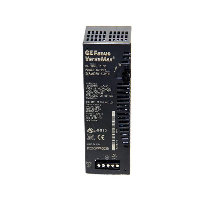
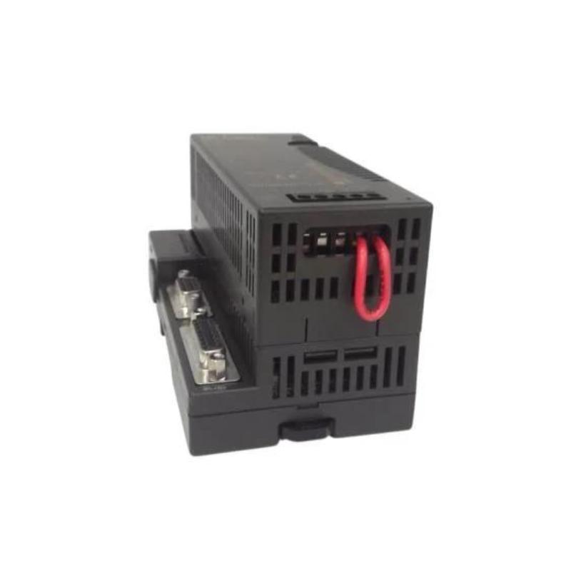
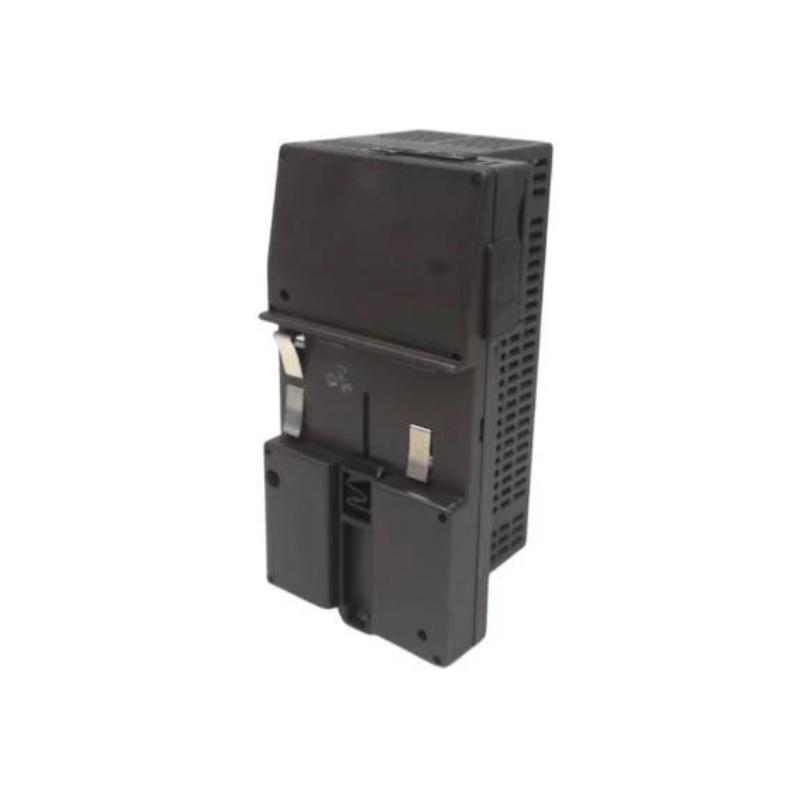
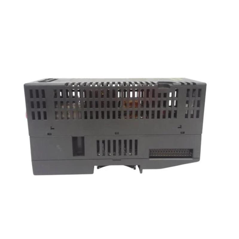
- GE
- IC200PWR101
- VersaMax Power Module
- USA
- 133.4 x 39 x 49 mm
- 0.25 kg
- Xiamen, China
- New & In Stock
- T/T, PayPal, Western Union
- 1 Year
- 1-3 Working Days
- DHL, UPS, TNT, FedEx and EMS.
- 24-Hour Service
- COO
- 4
Our advantage

Global Logistics
We have a 10-year logistics and express cooperation agreement, so our products can be shipped to any place in the world.

Brand new and original
Our products are imported in bulk from the place of origin. Because of the cooperative relationship, our products are all original and 100% new.

24-hour service
We provide 7*24 hours service to our customers. We will be there whenever you need us.

Price advantage
All our products are priced very favorably because we have our own warehouse and supply.
| Company Information | |||
| [email protected] | |||
| Mobile | +8615980777398 | ||
| +8615980777398 | |||
| 15980777398 |
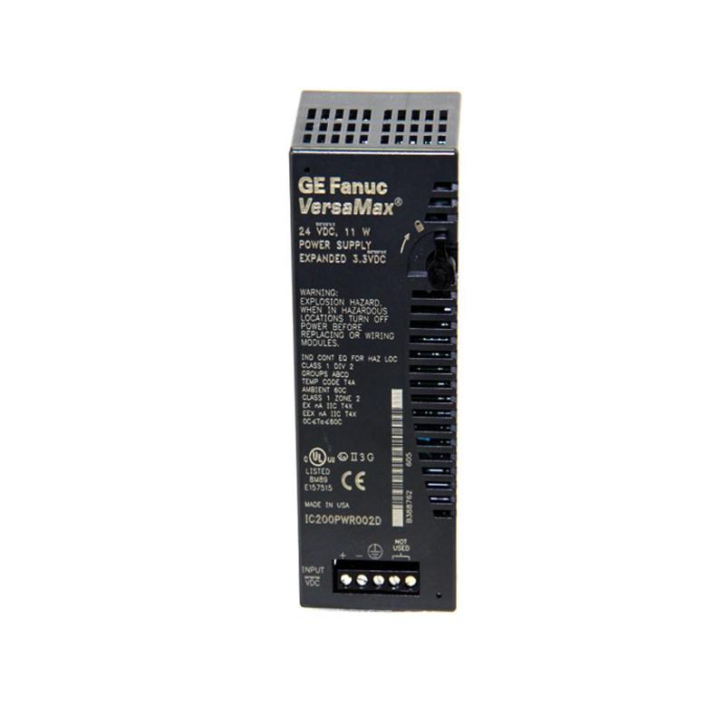
Product Overview
The GE IC200PWR101 VersaMax Power Module is a compact power module developed for the GE VersaMax PLC and distributed I/O platform. It is responsible for delivering stable operating power to the VersaMax backplane, enabling reliable operation of CPUs, communication modules, and digital or analog I/O modules within industrial automation systems.
As the primary power source for a VersaMax station, the IC200PWR101 plays an essential role in maintaining continuous system operation. Proper power distribution minimizes the risk of PLC resets, communication interruptions, I/O failures, and unexpected equipment downtime caused by unstable electrical conditions.
Designed for industrial control cabinets, the module is suitable for applications including factory automation, process control, material handling, packaging machinery, water treatment, and energy management systems.
The supplied product information is:
- Manufacturer: GE
- Product Family: VersaMax
- Model: IC200PWR101
- Product Type: VersaMax Power Module
- Dimensions: 133.4 × 39 × 49 mm
- Weight: 0.25 kg
- Application: Industrial Automation
- Primary Function: Power Distribution for VersaMax PLC and I/O Systems
Before installation, always verify the electrical specifications required by the automation system, including supply voltage, current capacity, grounding method, protective devices, and wiring configuration.
Technical Specifications
| Parameter | Specification |
|---|---|
| Manufacturer | GE |
| Product Family | VersaMax |
| Model | IC200PWR101 |
| Product Type | VersaMax Power Module |
| Primary Function | Power Distribution |
| System Platform | VersaMax PLC |
| Installation | Industrial Control Cabinet |
| Dimensions | 133.4 × 39 × 49 mm |
| Weight | 0.25 kg |
| Application | Industrial Automation |
| Power Distribution | VersaMax Backplane |
| Installation Position | Local VersaMax Station |
Function and Working Principle
The IC200PWR101 converts and distributes incoming electrical power to the VersaMax automation platform.
Typical power flow is illustrated below:
Incoming Industrial Power
↓
IC200PWR101 Power Module
↓
VersaMax Backplane
↓
CPU Module
↓
Communication Modules
↓
Digital / Analog I/O Modules
↓
Sensors and Field Devices
The power module provides the electrical energy required for all installed VersaMax components. Stable voltage and reliable power distribution ensure accurate data processing, communication integrity, and continuous machine operation.
Power instability may result in:
- PLC restart
- I/O communication loss
- Network interruptions
- Module faults
- Unexpected equipment shutdown
- Diagnostic alarms
Because many system faults originate from unstable power, the power module should be one of the first components checked during troubleshooting.
Role in Industrial Control Systems
Within a VersaMax installation, the IC200PWR101 performs several important functions:
- Supplies operating power to the VersaMax backplane
- Supports CPU operation
- Powers communication interfaces
- Supports local and remote I/O modules
- Maintains stable automation performance
- Reduces downtime caused by electrical disturbances
- Supports continuous industrial production
Reliable power distribution improves the stability of the complete automation system.
Typical Industrial Applications
Manufacturing Automation
The IC200PWR101 is suitable for:
- Automated assembly lines
- CNC equipment
- Robotic manufacturing cells
- Material handling systems
- Industrial conveyors
- Automated inspection machines
Continuous power helps reduce unexpected production interruptions.
Packaging Equipment
Typical applications include:
- Filling machines
- Packaging lines
- Labeling equipment
- Wrapping machines
- Cartoning systems
- Palletizing equipment
Stable system power improves synchronization between PLC logic and field devices.
Process Control
Industrial process applications include:
- Chemical plants
- Water treatment facilities
- Utility systems
- Pump stations
- Valve control systems
- Energy management systems
Reliable power supports uninterrupted process operation.
Distributed I/O Systems
Typical distributed architecture:
Main PLC
↓
Industrial Ethernet Network
↓
Remote VersaMax Station
↓
IC200PWR101
↓
VersaMax I/O Modules
↓
Field Equipment
This design reduces field wiring while maintaining centralized process control.
Installation Guide
1. Verify Product Identification
Confirm the installed module is:
GE IC200PWR101 VersaMax Power Module
Inspect for:
- Housing damage
- Bent connectors
- Broken locking tabs
- Loose terminals
- Moisture contamination
- Corrosion
- Burn marks
- Signs of overheating
Replace damaged equipment before installation.
2. Inspect Installation Environment
Verify:
- Cabinet cleanliness
- Ambient temperature
- Humidity level
- Ventilation
- Mechanical vibration
- Available installation space
Proper environmental conditions contribute to reliable long-term operation.
3. Verify Incoming Power
Before wiring:
- Confirm supply voltage
- Verify circuit protection
- Inspect grounding
- Check cable sizing
- Verify electrical isolation
Power should remain disconnected during installation.
4. Install the Module
Mount the IC200PWR101 securely in the designated VersaMax location.
Confirm:
- Correct orientation
- Secure mechanical attachment
- Proper engagement with the backplane
- Adequate clearance for cooling
5. Connect Electrical Wiring
Wire the module according to the approved control drawings.
Inspect:
- Terminal torque
- Wire identification
- Ground connection
- Cable insulation
- Routing of power cables
Avoid routing power cables parallel to sensitive communication wiring whenever possible.
6. Verify System Installation
Confirm:
- CPU installation
- Communication module installation
- I/O module seating
- Expansion module connections
- Backplane integrity
Loose module connections can create intermittent operating problems.
Commissioning Procedure
Step 1 — Mechanical Inspection
Verify secure installation.
Step 2 — Electrical Inspection
Inspect wiring and terminals.
Step 3 — Ground Verification
Confirm grounding continuity.
Step 4 — Apply Power
Energize the system according to plant procedures.
Step 5 — Verify Power Module Status
Observe normal startup.
Step 6 — Verify CPU Operation
Confirm successful PLC initialization.
Step 7 — Verify Communication
Check network connectivity and communication status.
Step 8 — Verify I/O Operation
Confirm normal operation of all installed I/O modules.
Step 9 — Functional Test
Operate connected equipment under normal production conditions.
Step 10 — Stability Observation
Monitor system performance during startup and continuous operation.
Troubleshooting Guide
Problem 1: VersaMax Station Does Not Start
Possible causes:
- No incoming power
- Incorrect wiring
- Open circuit protection
- Loose terminals
- Internal module failure
- Backplane connection problem
Recommended Checks
- Verify input voltage.
- Inspect circuit breakers or fuses.
- Check wiring integrity.
- Verify module installation.
- Inspect backplane connections.
Problem 2: PLC Restarts Repeatedly
Possible causes include:
- Voltage fluctuations
- Loose wiring
- Excessive system loading
- Electrical interference
- Intermittent power interruptions
Measure voltage during actual machine operation.
Problem 3: Multiple I/O Modules Become Unavailable
Possible causes:
- Backplane fault
- Insufficient power
- Loose module installation
- Power distribution interruption
- Wiring defects
Inspect the complete power distribution path before replacing I/O modules.
Problem 4: Communication Failures
Communication interruptions may result from:
- Unstable supply voltage
- Grounding issues
- Electrical noise
- Communication module faults
- Power interruptions
Always verify power quality before replacing communication hardware.
Problem 5: Module Temperature Is High
Possible causes include:
- Poor ventilation
- High cabinet temperature
- Continuous overload
- Restricted airflow
- Internal component aging
Inspect ventilation and cooling conditions.
Problem 6: Startup Voltage Drops
Possible causes:
- High inrush current
- Insufficient power source
- Loose terminals
- Undersized wiring
- Excessive system loading
Voltage should be monitored during machine startup.
Problem 7: Expansion Causes System Instability
Possible causes include:
- Power capacity exceeded
- Additional module load
- Incorrect installation
- Backplane issues
Review total power consumption whenever system expansion occurs.
Problem 8: Module Replacement Does Not Correct the Fault
If replacing the IC200PWR101 does not solve the problem, inspect:
- Incoming power
- Grounding
- Protective devices
- Backplane
- CPU
- Communication modules
- I/O modules
- Cabinet wiring
The actual fault may be located elsewhere in the automation system.
Power Distribution Best Practices
For reliable operation:
- Maintain stable input voltage.
- Verify proper grounding.
- Tighten wiring terminals periodically.
- Keep ventilation openings unobstructed.
- Separate power wiring from communication cables.
- Monitor cabinet temperature.
- Avoid operating near maximum load continuously.
- Inspect wiring during scheduled maintenance.
Preventive Maintenance
| Inspection Item | Recommended Check |
|---|---|
| Housing | Inspect for cracks or damage |
| Mounting | Verify secure installation |
| Wiring | Check terminal tightness |
| Grounding | Verify continuity |
| Input Voltage | Measure periodically |
| Backplane | Inspect electrical connection |
| Ventilation | Clean dust and obstructions |
| Connected Modules | Verify secure installation |
| Cabinet Temperature | Monitor regularly |
| System Diagnostics | Review fault logs |
Routine maintenance improves system reliability and reduces unexpected downtime.
Systematic Fault Diagnosis
Recommended troubleshooting sequence:
Incoming Power
↓
Circuit Protection
↓
IC200PWR101
↓
VersaMax Backplane
↓
CPU Module
↓
Communication Modules
↓
I/O Modules
↓
Field Devices
Following this sequence helps identify:
- Incoming power faults
- Wiring problems
- Grounding issues
- Power module failures
- Backplane faults
- CPU faults
- Communication problems
- I/O failures
- External equipment faults
IC200PWR101 Troubleshooting Table
| Symptom | Possible Cause | Recommended Action |
|---|---|---|
| No system power | Incoming supply failure | Verify power source |
| PLC resets | Voltage instability | Measure supply under load |
| I/O modules offline | Backplane or power issue | Inspect module seating |
| Communication interruption | Unstable power | Verify grounding and voltage |
| Excessive module temperature | Poor ventilation | Improve cooling |
| Startup failure | High inrush current | Verify available power |
| System unstable after expansion | Excessive load | Review total power capacity |
| Fault remains after replacement | External system problem | Inspect controller and wiring |
Key Advantages
- Designed specifically for GE VersaMax automation systems
- Provides reliable power distribution
- Supports PLC and distributed I/O stations
- Compact industrial construction
- Easy installation in control cabinets
- Supports communication and expansion modules
- Suitable for continuous industrial operation
- Dimensions of 133.4 × 39 × 49 mm
- Lightweight design with 0.25 kg weight
- Ideal for manufacturing and process automation
Technical FAQs
What is the GE IC200PWR101?
The GE IC200PWR101 is a VersaMax Power Module that provides operating power to GE VersaMax PLC and distributed I/O systems.
What is its primary function?
Its primary function is to distribute stable electrical power to the VersaMax backplane and installed automation modules.
What are the dimensions of the IC200PWR101?
The module measures 133.4 × 39 × 49 mm.
What is the weight of the module?
The supplied weight is 0.25 kg.
Can unstable power affect PLC operation?
Yes. Unstable power can cause controller resets, communication failures, I/O faults, and unexpected equipment shutdown.
Why does the PLC restart unexpectedly?
Possible causes include voltage fluctuations, loose wiring, excessive loading, poor grounding, or interruptions in the incoming power supply.
Why do multiple I/O modules fail simultaneously?
A common power distribution problem, backplane issue, or insufficient power capacity may affect multiple modules at the same time.
Why does the module become hot during operation?
Poor ventilation, high ambient temperature, overload conditions, or aging internal components may increase operating temperature.
Should the IC200PWR101 be replaced immediately after a power fault?
No. Verify the incoming electrical supply, wiring, grounding, protective devices, and connected load before replacing the module.
How can I determine whether the IC200PWR101 is faulty?
Check the input power, wiring, grounding, backplane, and connected system load. If the incoming power is normal but the module cannot provide stable operating power to the VersaMax station, further inspection or replacement may be required.
What should be checked if replacing the IC200PWR101 does not solve the problem?
Inspect the electrical supply, protective devices, controller, backplane, communication modules, I/O modules, grounding system, and cabinet wiring to locate the root cause.
Conclusion
The GE IC200PWR101 VersaMax Power Module is a critical component that delivers stable power to GE VersaMax PLC and distributed I/O systems. Reliable power distribution ensures dependable controller operation, communication stability, and consistent I/O performance in industrial automation environments.
With compact dimensions of 133.4 × 39 × 49 mm and a lightweight design of 0.25 kg, the module is suitable for installation in a wide range of industrial control cabinets.
Correct installation, proper grounding, secure wiring, adequate ventilation, and routine preventive maintenance are essential for long-term reliability. During troubleshooting, technicians should follow a structured diagnostic process from the incoming power supply through the power module, backplane, controller, communication modules, and field devices to accurately identify and resolve system faults.