

ProductPRODUCT
Featured products



Contact Us
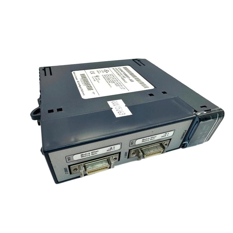
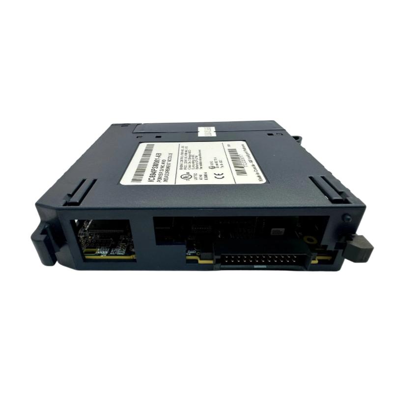
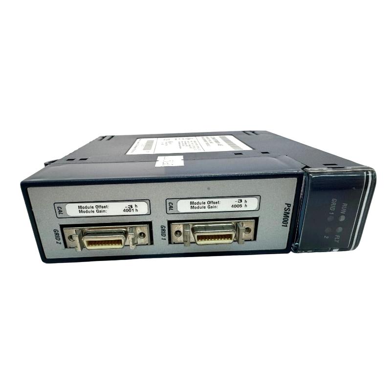
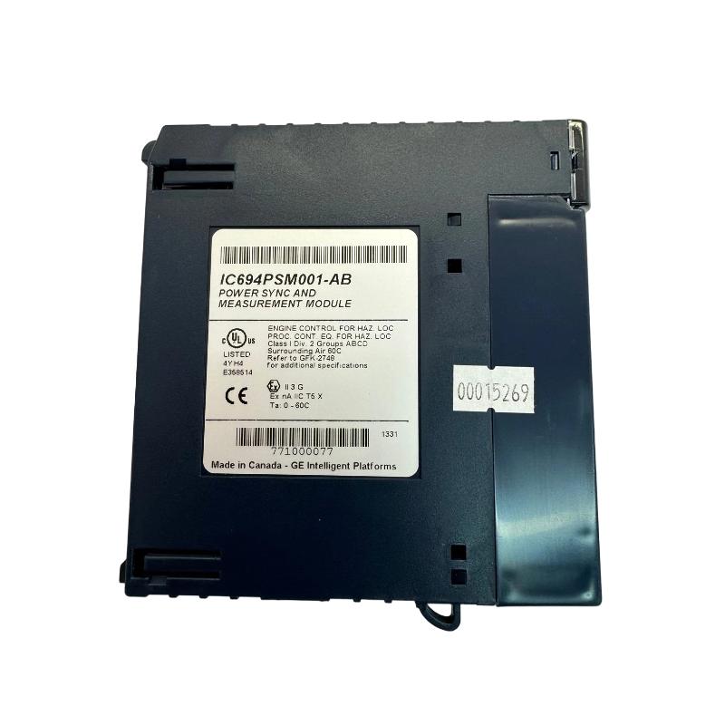
- GE
- IC694PSM001
- Power Synchronization And Measurement Module
- USA
- 50.8 x 146 x 137 mm
- 0.3 kg
- Xiamen, China
- New & In Stock
- T/T, PayPal, Western Union
- 1 Year
- 1-3 Working Days
- DHL, UPS, TNT, FedEx and EMS.
- 24-Hour Service
- COO
- 64
Our advantage

Global Logistics
We have a 10-year logistics and express cooperation agreement, so our products can be shipped to any place in the world.

Brand new and original
Our products are imported in bulk from the place of origin. Because of the cooperative relationship, our products are all original and 100% new.

24-hour service
We provide 7*24 hours service to our customers. We will be there whenever you need us.

Price advantage
All our products are priced very favorably because we have our own warehouse and supply.
| Company Information | |||
| [email protected] | |||
| Mobile | +8615980777398 | ||
| +8615980777398 | |||
| 15980777398 |
Product Overview
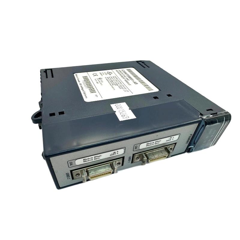
The GE IC694PSM001 Power Synchronization and Measurement Module is a specialized PLC system component designed for applications where electrical power conditions must be monitored and coordinated within an industrial automation architecture.
Unlike a conventional digital I/O module, a power synchronization and measurement module is associated with electrical-system monitoring and control functions. It can support applications where the PLC needs information related to power conditions, synchronization, or electrical measurements as part of a broader control strategy.
The specified dimensions of the GE IC694PSM001 are 50.8 × 146 × 137 mm, with a specified weight of 0.3 kg.
Because this type of module can be associated with electrical power monitoring, installation requires particular attention to system compatibility, wiring, measurement circuits, grounding, signal integrity, and electrical safety.
Product Identification
| Parameter | Specification |
|---|---|
| Manufacturer | GE |
| Series | IC694 |
| Model | IC694PSM001 |
| Product Type | Power Synchronization and Measurement Module |
| Main Function | Power Monitoring and Synchronization Support |
| Application | Industrial Automation / Power Control |
| Dimensions | 50.8 × 146 × 137 mm |
| Weight | 0.3 kg |
| Installation | PLC Rack / Industrial Control Cabinet |
| System Role | Electrical Measurement and Control Interface |
| Typical Application | Power-System Monitoring and Synchronization |
Technical Specifications
| Technical Item | Specification |
|---|---|
| Manufacturer | GE |
| Model | IC694PSM001 |
| Product Category | Power Synchronization and Measurement Module |
| Main Function | Electrical Measurement / Synchronization |
| Dimensions | 50.8 × 146 × 137 mm |
| Weight | 0.3 kg |
| Installation Environment | Industrial Control Cabinet |
| System Role | Power-System Interface |
| Application | Industrial Power and Automation Systems |
| Measurement Function | Power-System Parameter Monitoring |
| Synchronization Function | Supports System Synchronization Applications |
| Maintenance | Electrical, Wiring, Configuration, and Diagnostic Inspection |
The exact measurement channels, electrical input ranges, accuracy, isolation characteristics, synchronization parameters, terminal assignments, frequency range, and supported system configuration should be confirmed against the applicable technical documentation before installation.
What Is the GE IC694PSM001?
The IC694PSM001 is a specialized module intended for applications involving power synchronization and electrical measurement.
A simplified architecture can be represented as:
Electrical Power System
↓
Measurement / Synchronization Interface
↓
IC694PSM001
↓
PLC Control System
↓
Control Logic
↓
Power-System Equipment
The module can therefore form part of the interface between electrical-system conditions and the PLC control architecture.
Role in Industrial Automation
Industrial plants frequently need to monitor electrical conditions in addition to conventional machine I/O.
For example, an automation system may need information associated with:
- Power-system condition
- Synchronization
- Electrical operating status
- Generator-related control
- Utility and plant power coordination
- Electrical protection logic
- System alarms
A dedicated measurement and synchronization module can help integrate these requirements into the broader PLC control system.
Power Synchronization Concept
Power synchronization is particularly important when electrical sources or systems need to operate in coordination.
A simplified sequence is:
Power Source A
Power Source B
↓
Electrical Condition Measurement
↓
Synchronization Evaluation
↓
PLC / Control Logic
↓
Permissive or Control Action
The actual synchronization method depends on the electrical architecture and application.
For critical power systems, synchronization should never rely solely on a general PLC signal without the appropriate electrical protection and control equipment.
Installation Guide
1. Verify the Module
Confirm the module identification:
GE IC694PSM001
Inspect the housing for:
- Cracks
- Deformation
- Connector damage
- Corrosion
- Contamination
- Signs of overheating
- Physical impact
Do not install a damaged module.
2. Confirm System Compatibility
Before installation, verify:
- PLC rack compatibility
- CPU compatibility
- Slot assignment
- Power requirements
- Measurement-system architecture
- Associated modules
- Electrical-system configuration
A measurement module should be treated as part of the complete control architecture rather than as an isolated component.
3. Check Physical Dimensions
The specified dimensions are:
50.8 × 146 × 137 mm
Provide sufficient cabinet clearance for:
- Module insertion
- Terminal access
- Wiring
- Cable routing
- Ventilation
- Maintenance
Avoid installing the module in a location where power cables or other equipment can mechanically interfere with it.
4. Check Weight
The specified weight is:
0.3 kg
Although the module is relatively lightweight, associated measurement wiring and terminal connections can impose additional mechanical stress.
Ensure the cabinet and rack are adequately supported.
5. Electrical Safety Preparation
Power measurement and synchronization circuits can involve hazardous electrical energy.
Before installation:
- Place the equipment in a safe state.
- Isolate applicable electrical sources.
- Apply appropriate lockout/tagout procedures.
- Verify the absence of hazardous voltage.
- Discharge stored energy where applicable.
- Follow plant electrical-safety requirements.
- Use appropriately qualified personnel for electrical work.
Never assume that a PLC rack is de-energized simply because the CPU is stopped.
6. Install the Module
Align the IC694PSM001 with the designated rack position.
Insert it carefully until fully seated.
Avoid:
- Excessive insertion force
- Connector impact
- Misalignment
- Twisting
- Contamination
7. Secure the Module
Check:
- Module seating
- Mechanical retention
- Connector engagement
- Rack alignment
- Clearance around the module
A poor connection can produce unstable measurements or intermittent system faults.
Measurement Circuit Preparation
Before connecting measurement circuits, prepare a detailed wiring schedule.
Record:
- Measurement point
- Signal source
- Terminal assignment
- Expected electrical range
- Reference or common
- Protection arrangement
- PLC data assignment
This documentation is particularly important in power-related systems.
Wiring Inspection
Before applying power, inspect measurement wiring for:
- Correct terminal assignment
- Proper conductor size
- Secure terminals
- Correct polarity where applicable
- Proper insulation
- Appropriate shielding
- Correct grounding
- Separation from high-energy conductors
Never connect an unknown electrical source to a measurement terminal.
Power Measurement Wiring
The exact measurement connection depends on the application and supported electrical architecture.
Before wiring, confirm:
- Voltage range
- Current or measurement method
- Phase arrangement
- Frequency
- Ground/reference arrangement
- Isolation requirements
- Protective devices
Do not infer electrical input ratings from the module’s physical appearance.
Synchronization Wiring
Synchronization applications require accurate electrical information.
Potential parameters may include:
- Voltage
- Frequency
- Phase relationship
- Source status
- Synchronization permissive
The control strategy should clearly define which conditions must be satisfied before synchronization is permitted.
Cable Routing
Measurement wiring should be routed carefully.
Where appropriate, separate measurement cables from:
- Motor power cables
- High-current conductors
- Variable-frequency drive output cables
- Switching equipment
- Welding circuits
Poor routing can introduce electrical noise and produce unstable measurements.
Grounding and Shielding
Grounding should follow the electrical design and plant standards.
Where shielded measurement cables are used, terminate shields according to the system grounding strategy.
Incorrect grounding can result in:
- Measurement noise
- Ground loops
- Communication interference
- Unstable values
Commissioning Procedure
Step 1 – Mechanical Inspection
Confirm:
- Module correctly installed
- Rack secure
- Connectors engaged
- Wiring organized
- No visible damage
Step 2 – Electrical Inspection
Before energizing the measurement circuit, verify:
- Correct voltage source
- Correct terminal
- Correct polarity
- Correct reference
- Proper protection
- Secure connections
Step 3 – Power Up the PLC
Restore PLC power according to the approved startup procedure.
Observe the module and controller diagnostic status.
Step 4 – Verify Module Recognition
Confirm that the PLC configuration corresponds to the installed module.
Check for:
- Configuration errors
- Missing-module indications
- Diagnostic faults
- Unexpected status conditions
Step 5 – Verify Measurement Values
Compare displayed or reported values with an independent, properly rated measurement instrument where appropriate.
Check:
- Expected magnitude
- Stability
- Phase information where applicable
- Frequency
- Source status
Do not connect inappropriate test equipment directly to hazardous circuits.
Step 6 – Verify Synchronization Logic
Test synchronization permissives under controlled conditions.
Confirm that the programmed logic responds correctly to:
- Acceptable voltage
- Acceptable frequency
- Correct phase relationship
- Source availability
- Required permissive conditions
Step 7 – Test Abnormal Conditions
Where the plant test procedure permits, verify responses to conditions such as:
- Loss of source
- Out-of-range measurement
- Synchronization mismatch
- Communication failure
- Measurement interruption
All tests must follow the electrical system’s approved commissioning and safety procedures.
Troubleshooting Guide
Fault 1 – Module Is Not Recognized
Possible Causes
- Incorrect rack configuration
- Module not fully seated
- Rack connector problem
- CPU configuration issue
- Power problem
- Hardware fault
Diagnostic Sequence
Check:
Power → Rack → Module Seating → Configuration → Diagnostics
Fault 2 – Measurement Values Are Incorrect
Possible causes include:
- Incorrect wiring
- Wrong measurement configuration
- Incorrect scaling
- Electrical interference
- Sensor or transformer problem
- Grounding issue
- Hardware fault
Compare the PLC value against a suitable independent measurement.
Fault 3 – Measurement Value Is Unstable
Possible Causes
- Electrical noise
- Poor shielding
- Ground loop
- Loose connection
- Unstable source
- Incorrect wiring
- Measurement circuit problem
Inspect wiring and grounding before replacing the module.
Fault 4 – Synchronization Is Not Permitted
Possible Causes
- Voltage mismatch
- Frequency mismatch
- Phase mismatch
- Source unavailable
- Incorrect control configuration
- Measurement signal problem
- Synchronization permissive not satisfied
Determine which condition is preventing synchronization.
Fault 5 – Synchronization Status Changes Intermittently
Possible causes include:
- Unstable measurement
- Electrical noise
- Loose wiring
- Frequency fluctuation
- Voltage fluctuation
- Poor synchronization thresholds
- Intermittent communication
Trend the measurement values to identify whether the problem is electrical or control-related.
Fault 6 – Measurement Is Always Zero
Possible causes:
- No measurement signal
- Incorrect wiring
- Open circuit
- Incorrect terminal
- Configuration problem
- Input circuit problem
Verify the signal at the appropriate point using properly rated test equipment.
Fault 7 – Measurement Is Permanently High
Possible causes:
- Incorrect signal source
- Wiring error
- Scaling problem
- Incorrect reference
- Measurement circuit fault
Do not assume that the module is defective until the external measurement circuit has been checked.
Fault 8 – PLC Reports Configuration Error
Possible causes include:
- Incorrect module definition
- Wrong slot assignment
- Unsupported configuration
- Firmware mismatch
- Hardware mismatch
Compare the actual rack arrangement with the engineering configuration.
Fault 9 – PLC System Resets During Power Events
Possible causes:
- Control power instability
- Electrical interference
- Grounding problem
- Power-supply issue
- Incorrect wiring
- Environmental conditions
Investigate control power and electrical-system events separately.
Fault 10 – Measurement Becomes Incorrect After Maintenance
Possible causes:
- Reversed wiring
- Loose terminal
- Incorrect cable
- Changed configuration
- Incorrect scaling
- Grounding change
Always compare the post-maintenance configuration with the documented original configuration.
Fault Diagnosis Flow
A practical diagnostic path is:
Electrical Source
↓
Measurement Circuit
↓
Wiring / Protection
↓
IC694PSM001
↓
PLC Rack
↓
CPU
↓
Configuration
↓
Control Logic
↓
Power-System Equipment
This sequence helps identify whether the problem is external to the module or actually originates inside the PLC hardware.
Preventive Maintenance
Module Inspection
Inspect the IC694PSM001 for:
- Housing damage
- Connector condition
- Corrosion
- Contamination
- Heat discoloration
- Mechanical looseness
Wiring Inspection
Check:
- Terminal tightness
- Cable insulation
- Cable identification
- Shielding
- Grounding
- Mechanical strain
Measurement Verification
Periodically compare important measurement values against an appropriate calibrated reference instrument where required by the plant maintenance program.
This can identify:
- Scaling errors
- Sensor degradation
- Wiring problems
- Measurement drift
Environmental Inspection
Maintain appropriate:
- Temperature
- Humidity
- Ventilation
- Cleanliness
- Vibration control
Configuration Backup
Maintain current records of:
- PLC configuration
- Measurement settings
- Synchronization parameters
- I/O assignments
- Program revision
- Associated electrical-system configuration
Preventive Maintenance Table
| Maintenance Area | Recommended Action |
|---|---|
| Module Housing | Inspect for physical damage |
| Rack Connection | Check seating and connector condition |
| Measurement Wiring | Inspect terminals and insulation |
| Grounding | Verify according to system design |
| Shielding | Inspect cable shields |
| Measurement Values | Compare against suitable reference |
| Configuration | Maintain current backup |
| Cabinet | Keep clean and dry |
| Environment | Monitor temperature and vibration |
| Diagnostics | Review abnormal status |
Industrial Applications
Generator Systems
Power synchronization and measurement functions can be relevant to systems involving multiple electrical sources.
Potential control objectives include:
- Source monitoring
- Synchronization permissives
- Generator status
- Electrical condition monitoring
Actual generator control must use the appropriate dedicated protection and synchronization equipment.
Utility and Plant Power Systems
Industrial facilities may coordinate electrical power from:
- Utility sources
- Generator systems
- Plant distribution systems
- Auxiliary power systems
Measurement information can be integrated into a broader automation architecture.
Industrial Power Monitoring
The module can participate in control architectures where electrical conditions need to be monitored by the PLC.
Examples include:
- Voltage monitoring
- Frequency monitoring
- Source status
- Synchronization conditions
- Electrical alarms
Automated Power Switching
In systems where electrical sources are switched or coordinated, measurement information can support control permissives.
A simplified architecture is:
Source Monitoring
↓
Measurement
↓
PLC Logic
↓
Switching Permissive
↓
Electrical Switching Equipment
The switching equipment itself must be appropriately rated for the electrical application.
Critical Power Applications
Power synchronization can be particularly important in applications where an interruption or incorrect switching sequence can affect production.
Examples may include:
- Manufacturing facilities
- Process plants
- Industrial utility systems
- Standby generation systems
- Critical production equipment
Such applications require coordinated electrical protection, interlocking, and control design.
System Integration
A typical architecture may contain:
Electrical Source
↓
Measurement / Protection
↓
IC694PSM001
↓
PLC CPU
↓
Automation Logic
↓
Operator Interface / Control Equipment
The IC694PSM001 should be considered one element of the complete power-control system rather than a substitute for dedicated electrical protection equipment.
Replacement Procedure
1. Record the Existing Configuration
Before replacement, document:
- Module position
- Wiring
- Measurement assignments
- Configuration parameters
- Synchronization settings
- Diagnostic status
2. Back Up PLC Data
Maintain copies of:
- PLC program
- Hardware configuration
- Measurement configuration
- Synchronization settings
- Relevant system parameters
3. Isolate Electrical Energy
Shut down the system and isolate all applicable energy sources.
Power-system measurement circuits may remain hazardous even when the PLC is stopped.
4. Disconnect Wiring
Label every conductor before disconnecting it.
Ensure measurement circuits are safely isolated according to the electrical design.
5. Remove the Existing Module
Release the module and remove it carefully from the rack.
6. Inspect the Rack
Check:
- Rack connector
- Mounting position
- Adjacent modules
- Contamination
- Mechanical damage
7. Install the Replacement
Install the replacement module carefully.
Confirm that it is fully seated and secured.
8. Reconnect Measurement Circuits
Reconnect each conductor according to the documented wiring arrangement.
Double-check every connection.
9. Restore Configuration
Verify or restore:
- PLC hardware configuration
- Measurement parameters
- Synchronization settings
- I/O assignments
10. Commission the System
Verify:
- Module recognition
- Measurement accuracy
- Signal stability
- Synchronization permissives
- PLC diagnostics
- Overall power-system operation
Replacement Considerations
| Parameter | Specification / Check |
|---|---|
| Manufacturer | GE |
| Model | IC694PSM001 |
| Product Type | Power Synchronization and Measurement Module |
| Dimensions | 50.8 × 146 × 137 mm |
| Weight | 0.3 kg |
| Rack Compatibility | Confirm |
| Measurement Configuration | Confirm |
| Electrical Input Requirements | Confirm |
| Synchronization Architecture | Confirm |
| Wiring Arrangement | Confirm |
| Grounding | Confirm |
| Protection | Confirm |
| PLC Configuration | Confirm |
Physical dimensions alone are not sufficient for selecting a replacement. Electrical characteristics and complete system compatibility must also be confirmed.
Key Advantages
- Designed for power-system measurement and synchronization applications
- Integrates electrical-system information into a PLC architecture
- Supports specialized industrial power-control applications
- Provides a dedicated interface for measurement-related functions
- Can participate in synchronization permissive logic
- Suitable for industrial automation environments
- Compact module design
- Dimensions: 50.8 × 146 × 137 mm
- Weight: 0.3 kg
- Can support centralized monitoring of electrical conditions within a compatible control system
Technical FAQs
What is the GE IC694PSM001?
The GE IC694PSM001 is identified as a Power Synchronization and Measurement Module for use within a compatible industrial PLC and power-control architecture.
What are the dimensions of the IC694PSM001?
The specified dimensions are 50.8 × 146 × 137 mm.
What is the weight of the IC694PSM001?
The specified weight is 0.3 kg.
What is the purpose of a power synchronization and measurement module?
It provides an interface for monitoring electrical conditions and supporting synchronization-related control functions within an automation architecture.
Why is synchronization important?
When electrical sources need to operate together, their electrical conditions must be within appropriate limits before connection or coordinated operation is permitted.
Can the IC694PSM001 replace electrical protection equipment?
No. A PLC measurement or synchronization interface should not be considered a substitute for appropriately rated electrical protection and switching equipment.
Why might the measurement value be incorrect?
Potential causes include wiring errors, incorrect configuration, scaling problems, electrical interference, grounding issues, external measurement-device problems, or module faults.
Why does synchronization fail even though the module appears operational?
The electrical sources may not satisfy the required voltage, frequency, phase, availability, or permissive conditions. Configuration and measurement problems should also be investigated.
Why does the measurement value fluctuate?
Possible causes include unstable electrical conditions, electrical noise, poor shielding, grounding problems, loose connections, or measurement-circuit issues.
What should be checked before replacing the module?
Verify the electrical source, wiring, configuration, grounding, measurement circuit, rack connection, and diagnostic information first.
Is the IC694PSM001 suitable for high-voltage applications?
The actual suitability depends on the module’s specified electrical inputs and the complete measurement architecture. Hazardous electrical circuits must be handled by qualified personnel using appropriately rated equipment and protection.
How can measurement reliability be improved?
Use correct wiring, appropriate grounding and shielding, proper cable routing, stable electrical sources, accurate configuration, and periodic verification against suitable reference instruments.
Conclusion
The GE IC694PSM001 Power Synchronization and Measurement Module is a specialized component for industrial automation systems that need to integrate electrical measurement and synchronization-related information into a PLC control architecture. Its specified dimensions are 50.8 × 146 × 137 mm, and its specified weight is 0.3 kg.
Successful installation depends on more than simply mounting the module in the rack. The measurement circuit, wiring, grounding, configuration, electrical protection, and synchronization strategy must all be considered as part of the complete system.
During commissioning, technicians should first verify the hardware installation and electrical connections, then confirm module recognition, measurement stability, configuration, and synchronization permissives. During troubleshooting, following the complete signal path from electrical source → measurement circuit → wiring → IC694PSM001 → PLC → control logic → power equipment provides a structured way to isolate faults.
Because power synchronization can involve hazardous electrical energy and critical switching operations, all electrical connections, testing, isolation, and protection procedures should be performed according to the applicable engineering design and qualified maintenance practices. With proper integration and preventive maintenance, the IC694PSM001 can serve as a useful component in PLC-based industrial power monitoring and synchronization systems.