

ProductPRODUCT
Featured products
Contact Us
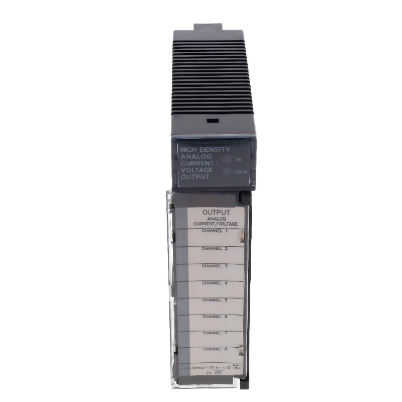
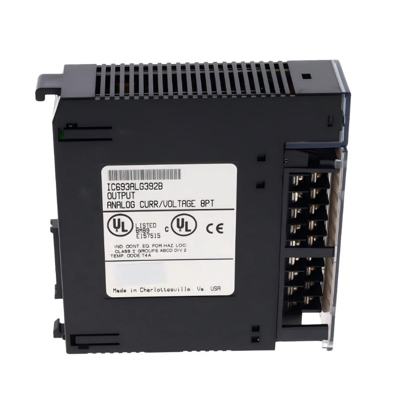
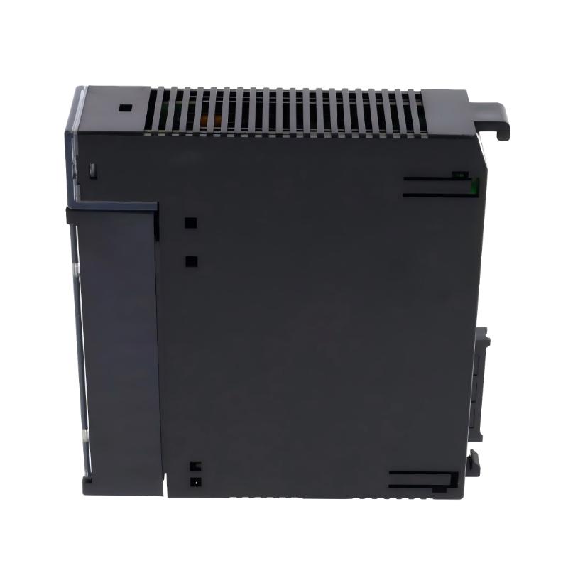
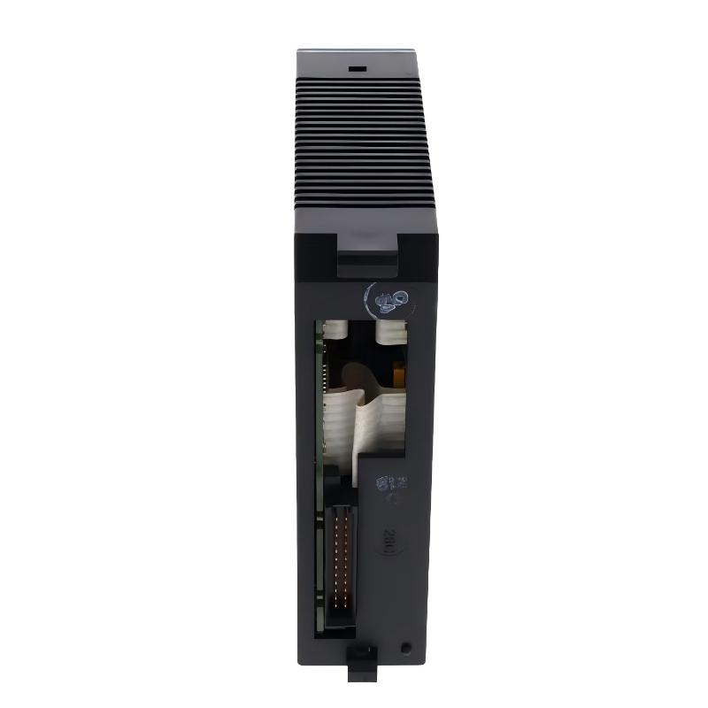
- GE
- IC693ALG392B
- Analog Output Module
- USA
- 127 x 35 x 110 mm
- 0.35 kg
- Xiamen, China
- New & In Stock
- T/T, PayPal, Western Union
- 1 Year
- 1-3 Working Days
- DHL, UPS, TNT, FedEx and EMS.
- 24-Hour Service
- COO
- 2
Our advantage

Global Logistics
We have a 10-year logistics and express cooperation agreement, so our products can be shipped to any place in the world.

Brand new and original
Our products are imported in bulk from the place of origin. Because of the cooperative relationship, our products are all original and 100% new.

24-hour service
We provide 7*24 hours service to our customers. We will be there whenever you need us.

Price advantage
All our products are priced very favorably because we have our own warehouse and supply.
| Company Information | |||
| [email protected] | |||
| Mobile | +8615980777398 | ||
| +8615980777398 | |||
| 15980777398 |
Product Overview
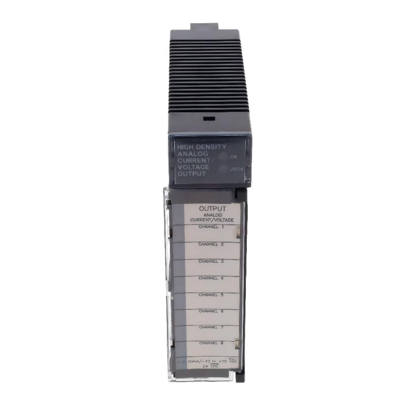
The GE Fanuc IC693ALG392B Analog Output Module is a high-density analog output module designed for GE Fanuc Series 90-30 PLC systems. It provides eight independent analog output channels, allowing a programmable logic controller to convert digital control data into electrical signals for industrial field devices.
In industrial automation, analog output signals are commonly used to control variable frequency drives, valve positioners, actuators, regulators, and other equipment that requires continuously adjustable control commands. The IC693ALG392B supports both voltage and current output modes, giving engineers flexibility when integrating different types of field instruments.
Each of its eight channels can be configured for one of four output ranges: 0 to +10 V, -10 to +10 V, 0 to 20 mA, or 4 to 20 mA. The selected output range depends on the connected device and the PLC configuration. All eight channels are updated approximately every 8 milliseconds, supporting coordinated analog control in industrial processes.
The module belongs to the GE Fanuc Series 90-30 automation platform. Its design supports applications involving process regulation, motor speed references, flow control, pressure adjustment, and temperature-control equipment. It can be installed in a compatible Series 90-30 or supported PACSystems RX3i configuration, subject to the applicable hardware and firmware requirements.
The IC693ALG392B is particularly useful in systems where several analog output signals must be generated from one PLC installation. Instead of using multiple lower-density modules, engineers can use its eight output channels to control several field devices from a single module.
Technical Specifications
| Parameter | Specification |
|---|---|
| Brand | GE Fanuc |
| Manufacturer | GE Fanuc Automation / GE Intelligent Platforms |
| Model | IC693ALG392B |
| Product Type | Analog Output Module |
| PLC Platform | Series 90-30 |
| Module Category | High-Density Analog Current/Voltage Output |
| Number of Channels | 8 |
| Output Type | Single-ended analog outputs |
| Voltage Output Range | 0 to +10 V DC |
| Bipolar Voltage Range | -10 to +10 V DC |
| Current Output Range | 0 to 20 mA |
| Current Output Range | 4 to 20 mA |
| Resolution | 15–16 bit, depending on selected range |
| Channel Update Rate | Approximately 8 ms for all channels |
| Field-to-Logic Isolation | 1500 V RMS |
| External Power Supply | 24 V DC |
| Backplane Power Consumption | Approximately 110 mA at 5 V DC |
| External 24 V DC Consumption | Approximately 315 mA |
| Output Configuration | Software configurable |
| Dimensions Provided | 127 × 35 × 110 mm |
| Weight Provided | 0.35 kg |
| Product Family | GE Fanuc Series 90-30 |
| Typical Applications | Process control, valve positioning, drive speed references, and analog instrumentation |
Note: The dimensions and weight are the supplied product-listing values. Confirm the exact hardware revision and physical dimensions before installation or shipment.
Function and Working Principle
The IC693ALG392B converts digital output values generated by the PLC CPU into analog electrical signals. These signals are transmitted to external equipment to regulate process variables such as speed, flow, pressure, temperature, and position.
1. Digital-to-Analog Signal Conversion
The PLC program calculates an output command according to the control logic and process conditions. The module receives the corresponding digital value and converts it into an analog voltage or current signal.
For example, a PLC may calculate that a control valve should open to 60% of its operating range. The IC693ALG392B can convert the programmed output value into a corresponding analog signal, provided that the channel has been configured for the correct output range.
This allows digital control systems to operate field devices that require continuous analog commands.
2. Eight Independent Output Channels
The module provides eight analog output channels. Each channel can be assigned to a separate control function, allowing one PLC module to manage several devices.
Typical examples include:
- Sending speed references to variable frequency drives.
- Controlling valve positioners.
- Adjusting pump operating speeds.
- Regulating pressure-control equipment.
- Providing setpoints to temperature controllers.
- Controlling other analog-compatible industrial instruments.
The eight-channel design can reduce the number of modules required in systems with multiple analog control points.
3. Configurable Voltage Outputs
The IC693ALG392B supports two voltage output ranges:
- 0 to +10 V DC
- -10 to +10 V DC
The 0 to +10 V range is commonly used for unipolar control signals, such as speed references and actuator commands.
The -10 to +10 V range supports bipolar control applications where both positive and negative command values are required.
The output range must be selected according to the receiving equipment’s specifications. Incorrect range selection can cause inaccurate control signals or prevent the connected device from operating correctly.
4. Configurable Current Outputs
The module also supports two current output ranges:
- 0 to 20 mA
- 4 to 20 mA
Current signals are widely used in industrial process instrumentation because they are suitable for transmitting control signals over industrial wiring distances.
The 4 to 20 mA range is especially common in process control. It can be used for valve position commands, actuator control, and other applications where the receiving instrument is designed for current-loop signals.
The selected current range must match the connected field device and the PLC program configuration.
5. Channel Update Performance
All eight output channels are updated approximately every 8 milliseconds. This provides a coordinated update cycle for applications that require multiple analog control signals.
The actual response of the complete control loop also depends on PLC scan time, program execution, field-device response, and process dynamics.
Role in Industrial Control Systems
The IC693ALG392B operates as an analog output interface between the PLC control program and external field equipment.
Within a Series 90-30 control system, the CPU processes input signals, executes programmed logic, and determines the required output values. The analog output module converts these values into voltage or current signals for connected devices.
PLC Process Control
The PLC CPU determines the output commands based on programmed control logic. The IC693ALG392B converts these commands into analog signals that can be understood by external instruments.
For example, a PLC may calculate a pump speed reference based on a pressure transmitter reading. The module then provides the corresponding analog output to a compatible variable frequency drive.
Actuator and Valve Control
Many industrial valves use analog signals to control opening positions. The module can generate the required voltage or current command for a compatible valve positioner.
This allows the PLC to regulate flow or pressure through continuous valve-position adjustments rather than relying only on fully open or fully closed commands.
Variable Frequency Drive Integration
The module can provide analog speed references to compatible AC drives. The PLC program can adjust the output signal according to process demand, production speed, or equipment operating conditions.
For example, a conveyor drive may receive a variable analog reference that determines its operating speed.
The electrical signal type and scaling must be compatible with the receiving drive’s analog input.
Distributed Control Functions
In larger automation systems, multiple analog output modules may be installed across different PLC racks or control panels. The IC693ALG392B can provide eight output points for a specific machine section or process area.
This arrangement allows engineers to organize analog control functions according to equipment groups and process requirements.
Industrial Applications
The GE Fanuc IC693ALG392B is suitable for industrial applications that require multiple configurable analog output signals.
1. Process Control Systems
Manufacturing and processing facilities often use analog outputs to regulate flow, pressure, temperature, and other process variables.
The module can provide control signals to compatible field instruments, allowing the PLC to adjust operating conditions according to programmed setpoints.
2. Valve Positioning Systems
Industrial control valves frequently use 4–20 mA or voltage signals to determine valve position.
The IC693ALG392B can generate the required command signals for compatible valve positioners. This makes it useful in applications involving fluid distribution, chemical processing, water treatment, and industrial utilities.
3. Variable Frequency Drive Control
Variable frequency drives often accept analog references for motor speed control.
The module can provide voltage or current speed commands to compatible drives. PLC logic can then adjust motor speed according to conveyor demand, pump pressure, or production requirements.
4. Pump and Fan Regulation
Industrial pumps and fans may require variable-speed operation to respond to changing process conditions.
By sending analog references to compatible drive systems, the module can support coordinated speed regulation and process optimization.
5. Temperature Control Systems
Some temperature-control systems use analog signals to adjust heating or cooling equipment.
The IC693ALG392B can provide output commands to compatible controllers or actuators. The actual temperature regulation strategy is determined by the PLC program and the connected control equipment.
6. Manufacturing and Assembly Equipment
Automated manufacturing equipment may use several analog control points for positioning, speed adjustment, pressure regulation, and material handling.
The eight output channels allow the module to serve multiple analog-controlled devices within one PLC installation.
Installation and System Integration
Correct installation and configuration are essential for reliable analog signal generation.
1. Verify PLC Compatibility
Before installing the IC693ALG392B, confirm that the PLC rack, CPU firmware, programming software, and module hardware revision are compatible.
The original release documentation identifies specific CPU firmware requirements. For CPU firmware versions 3.3 through 4.6, the module configuration requires 16 %I bits. With CPU firmware version 5.0 or later, the configuration can accept either 8 or 16 %I bits.
The original documentation also specifies IC641 programming software version 5.00 or later for configuring the module through the configurator function.
Always check the actual CPU firmware and module revision rather than assuming compatibility based only on the Series 90-30 product family.
2. Install the Module in a Compatible Rack
The module must be installed in a supported PLC baseplate or rack.
Before installation, isolate the control system according to the manufacturer’s procedures. Inspect the rack connector and module contacts for damage, contamination, or signs of corrosion.
Ensure that the module is correctly seated and secured.
3. Connect the External 24 V DC Supply
The IC693ALG392B requires an external 24 V DC supply connected directly to its terminal block.
The external power supply must have sufficient capacity for the module’s requirements and the connected system design.
Check supply polarity, voltage stability, wiring connections, and grounding before energizing the system.
4. Configure Output Ranges
Each channel must be configured for the required voltage or current range.
For example:
| Channel | Connected Device | Suggested Signal Type |
|---|---|---|
| Channel 1 | Variable frequency drive | 0–10 V or 4–20 mA |
| Channel 2 | Control valve positioner | 4–20 mA |
| Channel 3 | Pressure regulator | 4–20 mA |
| Channel 4 | Pump speed controller | 0–10 V |
| Channel 5 | Flow-control device | 4–20 mA |
| Channel 6 | Temperature controller | 0–10 V or 4–20 mA |
| Channel 7 | Auxiliary actuator | Application-dependent |
| Channel 8 | Additional control device | Application-dependent |
These are illustrative assignments only. Actual channel settings must match the receiving equipment’s electrical specifications.
5. Complete Field Wiring
Use appropriate signal wiring and terminal connections. Keep analog signal cables separated from high-voltage power cables and high-current conductors where required.
For installations exposed to electromagnetic interference, follow the manufacturer’s shielding, grounding, enclosure, and cable-routing recommendations.
The original product information includes specific enclosure and conduit requirements for certain RF interference environments. A suitable metal enclosure and appropriate wiring practices should be selected according to the installation conditions.
6. Test Analog Output Signals
After configuration and wiring, verify each output channel individually.
Use suitable measurement equipment to check voltage or current signals. Compare the measured values with the programmed PLC output values and confirm that the connected field devices respond correctly.
Document channel assignments, output ranges, signal scaling, and calibration results for future maintenance.
Compatible System Components
The IC693ALG392B is designed for use within a compatible GE Fanuc PLC and field-instrumentation installation.
| Component | Function | Integration Considerations |
|---|---|---|
| GE Fanuc Series 90-30 CPU | Executes PLC logic and calculates output commands | Verify CPU firmware compatibility |
| Series 90-30 Baseplate | Provides module mounting and backplane connections | Confirm rack and slot compatibility |
| 24 V DC Power Supply | Supplies external module power | Verify voltage, polarity, and current capacity |
| IC641 Programming Software | Configures the PLC and module parameters | Use a compatible software version |
| Analog Control Valve | Receives analog position commands | Match the selected voltage or current range |
| Variable Frequency Drive | Receives motor speed references | Verify analog input type and scaling |
| Pressure Controller | Uses analog commands for pressure regulation | Confirm signal range and control direction |
| Flow Controller | Regulates process flow | Check current-loop or voltage compatibility |
| Temperature Controller | Receives analog setpoint or control signals | Verify the supported input signal |
| Industrial Control Cabinet | Protects PLC and field wiring | Provide suitable grounding and EMI protection |
The components listed are typical system elements and are not necessarily included with the IC693ALG392B module.
Alternative Models and Replacement Considerations
When maintaining a GE Fanuc Series 90-30 installation, replacement selection should consider the number of channels, signal types, resolution, update rate, power requirements, and PLC compatibility.
| Model | Product Description | Main Difference |
|---|---|---|
| IC693ALG390 | 2-Channel Analog Voltage Output Module | Provides two voltage output channels |
| IC693ALG391 | 2-Channel Analog Current Output Module | Designed for two current output channels |
| IC693ALG392 | 8-Channel Analog Current/Voltage Output Module | Same general eight-channel output family |
| IC693ALG442 | Analog Current/Voltage Combination Module | Combines analog input and output functions |
| IC694ALG392 | PACSystems RX3i / Series 90-30 Analog Output Module | Related eight-channel module for supported platforms |
These models are related products, not automatic drop-in replacements.
Before choosing an alternative, compare:
- Number of analog output channels.
- Voltage and current output ranges.
- Resolution and update rate.
- External 24 V DC supply requirements.
- PLC CPU and firmware compatibility.
- Module hardware revision.
- Rack and backplane compatibility.
- Programming software requirements.
- Terminal block and wiring arrangements.
A replacement module must be validated against the actual PLC configuration and the field devices connected to its output channels.
Key Advantages
Eight Analog Output Channels
The module provides eight independent analog output points, allowing one module to control several external devices.
Flexible Voltage and Current Signals
Support for 0–10 V, ±10 V, 0–20 mA, and 4–20 mA gives engineers flexibility when connecting different types of industrial equipment.
High-Resolution Output
Depending on the selected range, the module supports 15–16 bit conversion resolution, enabling detailed analog command values.
Coordinated Channel Updates
All eight channels are updated approximately every 8 milliseconds, supporting applications with multiple analog control requirements.
Field-to-Logic Isolation
The specified 1500 V RMS field-to-logic isolation helps separate field-side electrical circuits from the PLC logic side.
Series 90-30 Integration
The module is designed for GE Fanuc Series 90-30 systems and can be used in compatible automation configurations.
Multiple Industrial Applications
Its configurable signal types make it suitable for controlling drives, valves, regulators, and other analog-compatible equipment.
Technical FAQs
1. What is the GE Fanuc IC693ALG392B?
The IC693ALG392B is an eight-channel analog current/voltage output module designed for GE Fanuc Series 90-30 PLC systems.
2. How many output channels does the module provide?
It provides eight independent single-ended analog output channels.
3. What voltage output ranges are supported?
The module supports 0 to +10 V DC and -10 to +10 V DC output ranges.
4. What current output ranges are supported?
It supports 0 to 20 mA and 4 to 20 mA output ranges.
5. What is the module’s resolution?
The module supports 15–16 bit resolution, depending on the selected output range.
6. What is the channel update rate?
All eight channels are updated approximately every 8 milliseconds.
7. Does the IC693ALG392B require an external power supply?
Yes. The module requires an external 24 V DC supply connected directly to its terminal block.
8. Can it control a variable frequency drive?
Yes. It can provide a compatible analog speed reference to a drive that accepts the selected voltage or current signal. The drive’s analog input configuration and signal scaling must match the PLC output.
9. Is the IC693ALG392B compatible with every Series 90-30 CPU?
No. Compatibility depends on CPU firmware, module revision, and configuration settings. Check the manufacturer’s compatibility documentation before installation.
10. What is the difference between IC693ALG392B and IC693ALG392?
The IC693ALG392B is a specific hardware/version designation associated with CE mark approval. The full module revision and hardware identification should be checked when ordering a replacement.
Procurement and Maintenance Recommendations
The GE Fanuc IC693ALG392B is a specialized analog output module used in established industrial automation systems. Accurate model identification is important when sourcing replacement equipment.
Before purchasing, verify the complete catalog number, module revision, physical condition, terminal block condition, and compatibility with the installed PLC CPU. For used or refurbished units, request clear photographs and available functional test information.
During maintenance, inspect the module connector, terminal block, external 24 V DC supply, and analog signal wiring. Check for loose terminals, damaged insulation, unstable power, or electromagnetic interference that could affect output accuracy.
When troubleshooting, test the module’s output channels individually. Compare the measured voltage or current against the PLC program’s commanded value. Also verify channel configuration, output scaling, external power, and field-device wiring.
Keep a record of the CPU firmware version, module revision, channel assignments, signal ranges, and calibration results. This information can simplify future replacement and reduce commissioning time.
Conclusion
The GE Fanuc IC693ALG392B Analog Output Module is an eight-channel high-density analog output device for compatible Series 90-30 PLC installations. It supports configurable voltage outputs of 0–10 V and ±10 V, as well as current outputs of 0–20 mA and 4–20 mA.
With 15–16 bit resolution, an approximately 8 ms update rate, and 1500 V RMS field-to-logic isolation, the module provides a flexible interface between PLC control logic and industrial field devices.
Its eight output channels make it suitable for applications involving valve positioning, drive speed references, pressure regulation, flow control, and other analog-controlled processes. For replacement and maintenance projects, engineers should verify CPU firmware compatibility, module revision, external 24 V DC power, and channel configuration before installation.