

ProductPRODUCT
Featured products
Contact Us
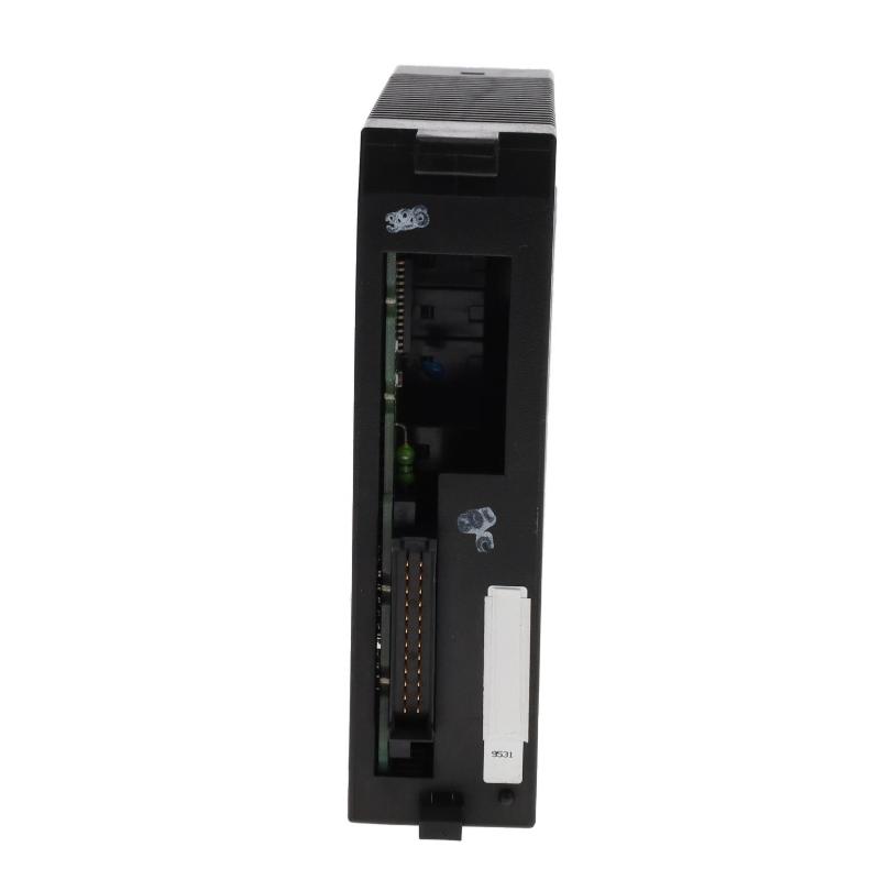
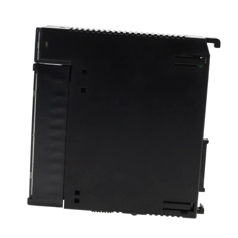
- GE
- IC693MDL940M
- Relay Output Module
- USA
- 150 × 55 × 100 mm
- 0.23 kg
- Xiamen, China
- New & In Stock
- T/T, PayPal, Western Union
- 1 Year
- 1-3 Working Days
- DHL, UPS, TNT, FedEx and EMS.
- 24-Hour Service
- COO
- 2
Our advantage

Global Logistics
We have a 10-year logistics and express cooperation agreement, so our products can be shipped to any place in the world.

Brand new and original
Our products are imported in bulk from the place of origin. Because of the cooperative relationship, our products are all original and 100% new.

24-hour service
We provide 7*24 hours service to our customers. We will be there whenever you need us.

Price advantage
All our products are priced very favorably because we have our own warehouse and supply.
| Company Information | |||
| [email protected] | |||
| Mobile | +8615980777398 | ||
| +8615980777398 | |||
| 15980777398 |
Product Overview
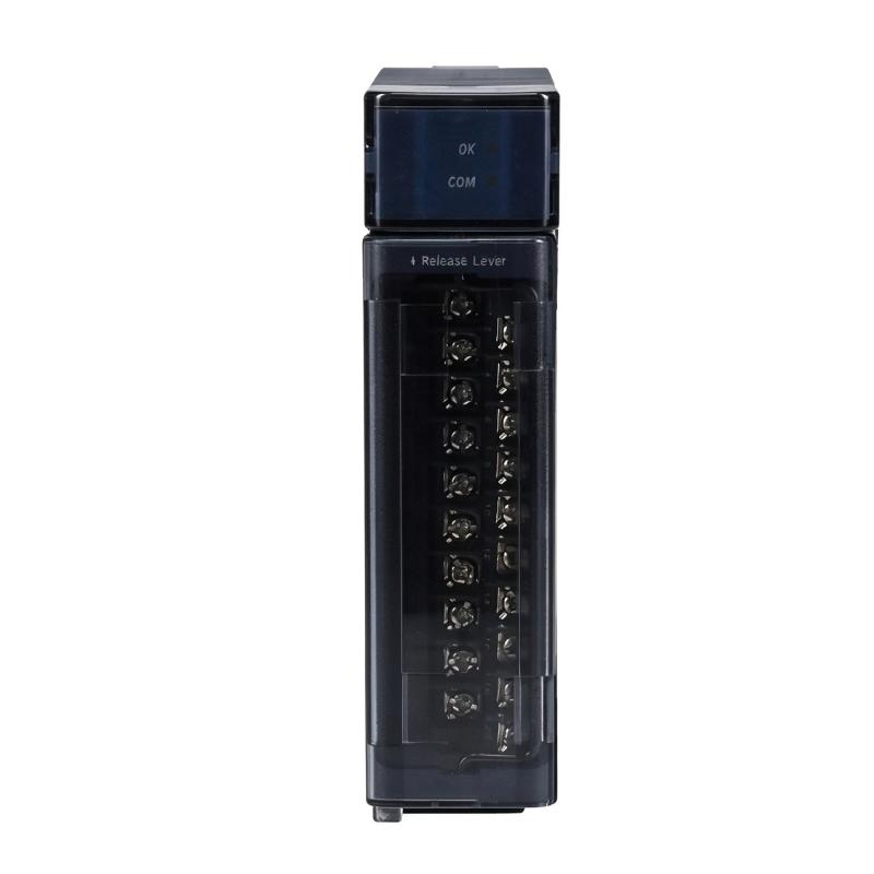
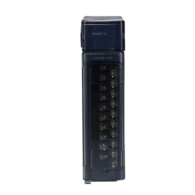
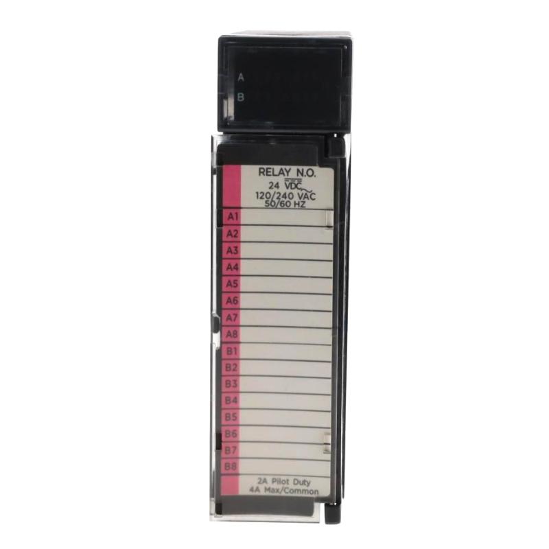
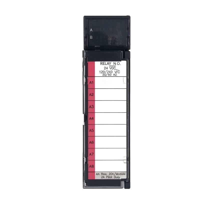
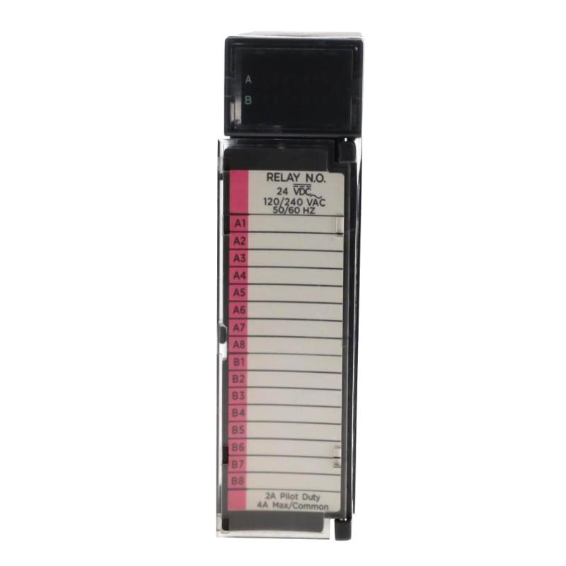
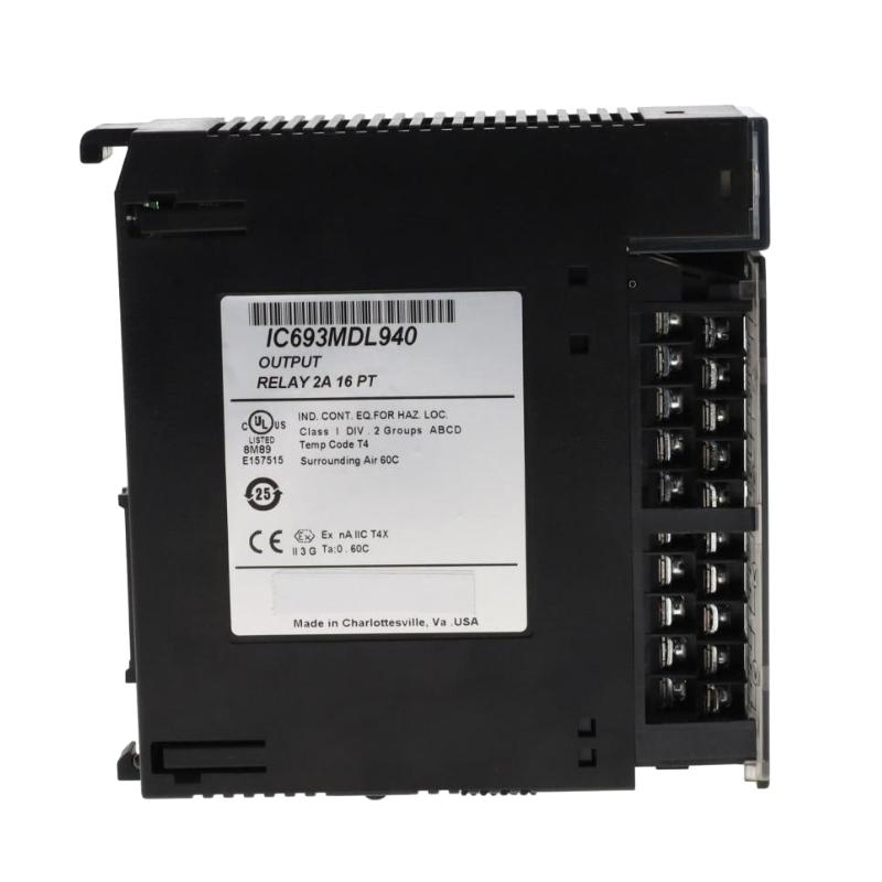
The GE IC693MDL940M Relay Output Module is a discrete output component designed for the GE Fanuc Series 90-30 programmable logic controller (PLC) platform. It provides relay-based switching between PLC control logic and external industrial devices, allowing a controller to operate equipment such as contactors, solenoid valves, indicator lamps, and other compatible field loads.
Relay output modules are commonly used when a PLC must switch external AC or DC circuits. Rather than supplying power directly to the connected field devices, the module uses internal relay contacts to switch a user-provided power source. This arrangement allows the PLC to control different types of loads within the electrical limits of the module.
The IC693MDL940 series provides 16 normally open relay output points, organized into four groups of four outputs. Each output has a maximum pilot-duty switching capacity of 2 A, while each group has a maximum common-terminal current of 4 A. The module supports a range of AC and DC field-load voltages, making it suitable for a variety of discrete control applications.
The IC693MDL940M is associated with the GE Fanuc Series 90-30 family. Its revision suffix should be checked when replacing an installed module, especially when the system has specific hardware or maintenance requirements.
For industrial maintenance teams, this module provides a practical interface between PLC logic and field-level switching devices. Correct wiring, load selection, and protection are essential for dependable operation.
Technical Specifications
| Parameter | Specification |
|---|---|
| Brand | GE Fanuc |
| Manufacturer | General Electric / GE Intelligent Platforms |
| Model | IC693MDL940M |
| Product Series | Series 90-30 |
| Product Type | Relay Output Module |
| Output Type | Normally Open Relay |
| Number of Outputs | 16 points |
| Output Arrangement | Four groups of four outputs |
| Maximum Current per Output | 2 A pilot duty |
| Maximum Current per Common | 4 A |
| Maximum Module Current | 16 A, subject to group and application limits |
| DC Operating Voltage | 5–30 V DC |
| AC Operating Voltage | 5–250 V AC, 50/60 Hz |
| Nominal Rated Voltage | 24 V DC / 120 or 240 V AC |
| Minimum Load Current | 10 mA |
| Maximum Inrush Current | 5 A |
| Maximum ON Response Time | 15 ms |
| Maximum OFF Response Time | 15 ms |
| Isolation | 1500 V between field side and logic side; 500 V between groups |
| Internal Relay Power | Supplied through the PLC backplane |
| Field Load Power | User supplied |
| Output Fuses | Not included |
| Dimensions Provided | 150 × 55 × 100 mm |
| Weight Provided | 0.23 kg |
| Typical Application | PLC-based discrete load switching |
Note: Electrical specifications are based on the IC693MDL940 series documentation. Confirm the exact revision-specific documentation and the module nameplate before installation. Dimensions and weight are the supplied listing values.
Function and Working Principle
The IC693MDL940M receives output commands from the PLC CPU through the Series 90-30 backplane. When the control program activates an output point, the corresponding relay changes state and closes its normally open contact. This allows an external power source to energize the connected field device.
When the PLC turns the output off, the relay contact returns to its normally open state and interrupts the field circuit.
1. Sixteen-Point Relay Switching
The module provides 16 individual relay output points. Each point can be assigned to a specific control function within the PLC program.
Typical controlled devices include:
- Motor starters and contactor coils.
- Solenoid valves.
- Alarm indicators.
- Signal lamps.
- Auxiliary relays.
- Other compatible AC or DC loads.
The 16-point arrangement allows multiple field devices to be controlled through a single PLC output module, helping reduce the number of separate output components required in a control cabinet.
2. Four-Group Output Arrangement
The 16 outputs are divided into four groups, with four points in each group. Each group has a common power terminal.
This grouping allows the output circuits to be arranged according to the electrical requirements of the connected loads. However, the maximum current limits for individual outputs and group commons must be observed.
Each output supports a maximum pilot-duty load of 2 A, while the common terminal supports a maximum of 4 A. These ratings must not be exceeded when multiple outputs in the same group operate simultaneously.
3. AC and DC Load Switching
The IC693MDL940 series supports both AC and DC field-load circuits within its specified operating ranges.
The documented operating ranges are:
- 5–30 V DC.
- 5–250 V AC at 50/60 Hz.
This flexibility allows the module to control different types of industrial equipment. The actual load voltage and current must be checked before wiring, and the user must provide the external power source for field devices.
4. Output Status Indication
The module provides LED indicators for monitoring the ON/OFF status of its output points. These indicators help maintenance personnel identify which output commands are active during troubleshooting and commissioning.
The LEDs indicate the module’s output status; they should not be treated as proof that the external load is receiving the correct voltage or operating successfully. Field wiring and load conditions must be checked separately.
5. Electrical Isolation
The IC693MDL940 series provides isolation between the field side and the PLC logic side, as well as isolation between output groups.
This separation helps protect the controller’s internal logic from electrical conditions on the field side and supports the use of different field circuits within the module’s rated limits.
Correct wiring and external protection remain necessary. Isolation does not remove the need to follow the manufacturer’s voltage, current, and grounding requirements.
Role in Industrial Control Systems
The IC693MDL940M acts as the output interface between the Series 90-30 PLC and external equipment. It converts the controller’s internal output commands into relay contact switching actions that operate field devices.
PLC Output Control
The PLC CPU executes the user program and determines when each output should be activated. The IC693MDL940M receives these commands through the backplane and switches the corresponding relay contacts.
For example, a PLC program may activate an output when a sensor detects a product at a conveyor station. The relay output can then energize a contactor or another control device to operate the associated machinery.
Field Device Operation
The module can control various field devices, provided that their electrical requirements fall within the relay output ratings.
A typical control sequence may involve:
- A sensor detects a process condition.
- The PLC evaluates the input signal and program logic.
- The CPU activates the assigned output point.
- The corresponding relay contact closes.
- The external field circuit energizes the connected device.
- When the control condition ends, the PLC deactivates the output and the relay contact opens.
This arrangement allows the PLC to coordinate multiple devices in an automated production process.
Control Cabinet Integration
The module is installed in a compatible Series 90-30 PLC baseplate. It receives its internal operating power through the backplane, while external power for the connected field loads is supplied separately by the user.
The four-group output arrangement should be considered when designing the field wiring. Each common terminal must be connected according to the load voltage and circuit configuration.
Industrial Applications
The IC693MDL940M is suitable for PLC-based systems that require relay switching of compatible AC or DC loads.
1. Motor Starter Control
The module can control motor starter or contactor coils within the specified electrical limits. The PLC can activate an output to initiate a motor-start sequence and deactivate it when the operating condition is no longer satisfied.
For larger motors, the relay output normally controls an appropriately rated contactor or interposing relay rather than switching the motor’s main power directly.
2. Solenoid Valve Operation
Industrial pneumatic and hydraulic systems often use solenoid valves to control fluid or compressed-air flow.
The IC693MDL940M can switch compatible solenoid valve circuits according to PLC commands. This allows valve operation to be coordinated with sensors, machine sequences, and safety interlocks.
The coil voltage, current, and inrush characteristics must be checked before connecting a solenoid valve.
3. Indicator and Alarm Circuits
The module can operate signal lamps, warning indicators, and compatible alarm devices.
A PLC may activate an indicator when a machine enters a particular operating state or when an abnormal condition is detected. This provides operators with a visible indication of process status.
4. Packaging and Assembly Equipment
Packaging and assembly machines often require multiple discrete outputs to operate contactors, valves, indicators, and auxiliary relays.
The 16-point arrangement allows the IC693MDL940M to control several devices within one PLC rack, helping coordinate different stages of a production sequence.
5. Material Handling Systems
Conveyors, sorting equipment, and transfer mechanisms use discrete control signals to coordinate their operation.
The relay output module can switch suitable control circuits for these devices, allowing the PLC to manage product movement and machine sequencing.
6. General Process Automation
The module may also be used in industrial process systems where discrete AC or DC loads must be switched according to PLC logic. Typical examples include auxiliary equipment, alarm circuits, and automated control panels.
Its suitability depends on the connected load’s voltage, current, switching frequency, and electrical characteristics.
Installation and System Integration
Correct installation is essential for reliable switching and safe operation.
1. Verify PLC Compatibility
Before installation, confirm that the module is intended for the GE Fanuc Series 90-30 platform and that the PLC baseplate and system configuration support it.
Check the complete model number and revision suffix. A similar-looking module from another PLC family may not be mechanically or electrically interchangeable.
2. Confirm Field Load Ratings
Check the voltage and current requirements of every connected device.
The IC693MDL940 series supports 5–30 V DC or 5–250 V AC field loads. Each output is rated for a maximum pilot-duty current of 2 A, and each common terminal is rated for a maximum of 4 A.
The load current must be evaluated both per output and per group. Do not assume that all 16 outputs can operate simultaneously at 2 A without considering the group-common limits and other electrical restrictions.
3. Provide External Field Power
The module does not supply operating power to external field devices. The user must provide the appropriate AC or DC source for the connected loads.
The PLC backplane supplies power for the module’s internal relay circuits. This is separate from the external field-load supply.
4. Install Appropriate Circuit Protection
The module does not have onboard output fuses. External circuit protection should therefore be selected according to the connected load, conductor ratings, and applicable electrical standards.
Where required, use suitable fuses or protective devices for individual field circuits or groups. Consider inductive loads such as contactor coils and solenoid valves when selecting suppression and protection components.
5. Observe Output Group Wiring
The 16 outputs are divided into four groups of four, with a common terminal for each group.
Plan the wiring so that each group is connected to the intended field supply and the total current remains within the specified limits. Verify terminal assignments against the module’s wiring diagram before energizing the system.
6. Avoid Hot Insertion or Removal
The IC693MDL940 series documentation states that the module is not compatible with hot-swap operations. Do not insert or remove the module while the PLC backplane is energized.
Before replacement or maintenance:
- Follow the plant’s lockout and isolation procedures.
- Remove power as required by the system instructions.
- Verify that the equipment is in a safe condition.
- Disconnect field wiring carefully.
- Replace the module with the correct model and revision.
- Restore power and test the output functions.
7. Test Output Operation
After installation, test each output point individually. Verify the PLC command, relay switching, field voltage, connected load response, and relevant interlocks.
Check that the LEDs correspond to the intended output states. Record the terminal assignments and field-device mapping for future maintenance.
Compatible System Components
The IC693MDL940M is designed to operate as part of a GE Fanuc Series 90-30 PLC system.
| Component | Function | Integration Considerations |
|---|---|---|
| Series 90-30 CPU | Executes PLC logic and output commands | Confirm CPU and system configuration compatibility |
| Series 90-30 baseplate | Provides module mounting and backplane connections | Verify supported slot and baseplate type |
| PLC power supply | Supplies power to the PLC system | Check backplane power requirements |
| Input modules | Receive signals from field sensors and switches | Coordinate input conditions with output logic |
| Relay output module | Switches external AC or DC field loads | Observe voltage, current, and group limits |
| Interposing relays | Provide an additional switching interface | Select according to coil and contact ratings |
| Contactors | Control motor power circuits | Use appropriate coil ratings and motor protection |
| Solenoid valves | Control pneumatic or hydraulic flow | Verify coil voltage and current |
| Indicator lamps | Display machine status | Match lamp ratings to the output circuit |
| External protective devices | Protect field wiring and loads | Select suitable fuses or circuit protection |
These components are examples of equipment used in a complete PLC installation. They are not necessarily supplied with the IC693MDL940M.
Alternative Models and Replacement Considerations
When replacing an IC693MDL940M, the replacement must match the required output type, channel count, voltage range, current capacity, and PLC platform.
| Related Model or Option | Description | Replacement Considerations |
|---|---|---|
| IC693MDL940 | Series 90-30 16-point relay output module | Confirm revision and electrical specifications |
| IC694MDL940 | Related 16-point relay output module for PACSystems RX3i configurations | Not automatically interchangeable; verify platform compatibility |
| IC693MDL916 | Series 90-30 relay output module with a different current configuration | Compare output ratings and channel arrangement |
| IC693MDL931 | Series 90-30 relay output module with a different contact configuration | Verify output type and electrical requirements |
| Compatible modern PLC output module | Potential option for system upgrades | May require wiring, software, and panel modifications |
Before choosing an alternative, verify:
- PLC family and baseplate compatibility.
- Number of output points.
- Normally open or normally closed contact configuration.
- AC and DC operating voltage ranges.
- Maximum current per output.
- Maximum current per common.
- Isolation requirements.
- Terminal arrangement and wiring.
- PLC program addressing and configuration.
- Installation and maintenance requirements.
A module with the same number of outputs is not necessarily a direct replacement. Always compare the complete electrical specifications and hardware compatibility.
Key Advantages
16 Relay Output Points
The module provides 16 normally open relay outputs, allowing one PLC slot to control multiple field devices.
Flexible AC and DC Switching
Its documented operating voltage ranges support a variety of compatible AC and DC control circuits.
Four-Group Output Arrangement
Four groups of four outputs provide a structured way to organize field circuits according to their electrical requirements.
Individual Output Status Indication
LED indicators help maintenance personnel identify commanded output states during troubleshooting and commissioning.
Field-to-Logic Isolation
Electrical isolation between the field side and PLC logic side helps separate external load circuits from internal controller electronics.
Series 90-30 Integration
The module is designed for the GE Fanuc Series 90-30 PLC platform, making it relevant to maintenance and spare-parts requirements for installed systems.
Technical FAQs
1. What is the GE IC693MDL940M?
The IC693MDL940M is a relay output module associated with the GE Fanuc Series 90-30 PLC family. It provides 16 normally open relay output points for switching compatible external AC or DC loads.
2. How many output channels does the module provide?
It provides 16 output points arranged in four groups of four. Each group has a common power terminal.
3. What is the maximum current per output?
The IC693MDL940 series is rated for a maximum pilot-duty load of 2 A per output. Each group common is rated for a maximum of 4 A.
4. What voltage can the module switch?
The documented operating ranges are 5–30 V DC and 5–250 V AC at 50/60 Hz. The actual load must remain within the module’s electrical ratings.
5. Does the module supply power to field devices?
No. The user must provide the AC or DC power required by the connected field devices. The PLC backplane supplies power for the module’s internal relay circuits.
6. Does the IC693MDL940M have output fuses?
No. The IC693MDL940 series does not include onboard output fuses. Appropriate external circuit protection must be provided for the field circuits.
7. Can the module control solenoid valves?
Yes, provided the valve coil voltage and current are within the module’s operating limits. Check the coil’s steady-state and inrush characteristics before connection.
8. Can the module be removed while the PLC is powered?
No. The IC693MDL940 series documentation states that it is not compatible with hot-swap operations. Follow the required isolation procedure before inserting or removing the module.
9. Is the IC694MDL940 interchangeable with the IC693MDL940M?
Not automatically. Although the models have related electrical functions, they are associated with different PLC platform configurations. Confirm the controller, baseplate, and system compatibility before substitution.
10. What should be checked when purchasing a replacement?
Verify the full catalog number and revision, physical condition, terminal condition, output operation, and compatibility with the installed Series 90-30 system. For critical applications, request suitable functional test information.
Procurement and Maintenance Recommendations
When sourcing the GE IC693MDL940M, begin by checking the complete catalog number and revision on the installed module. Confirm that the replacement has the required 16 normally open relay outputs and that its electrical specifications match the connected field loads.
For used or refurbished modules, request clear photographs of the front label, terminal area, and module housing. Check for damaged terminals, discoloration, corrosion, and signs of overheating. Where possible, request a functional test covering all 16 output points.
During maintenance, inspect field wiring and terminal connections regularly. Pay particular attention to the group-common current limits and the external protective devices. Since the module has no onboard output fuses, field-circuit protection should be reviewed as part of the maintenance process.
Keep the PLC cabinet clean and maintain suitable operating conditions. When replacing the module, isolate the PLC system according to the manufacturer’s instructions and verify each output after installation.
For long-term maintenance planning, retain a record of the module revision, wiring assignments, output mapping, and connected field-device ratings. This information helps reduce replacement errors and supports troubleshooting in legacy Series 90-30 control systems.
Conclusion
The GE IC693MDL940M Relay Output Module is a 16-point discrete output component designed for GE Fanuc Series 90-30 PLC applications. Its four-group arrangement, normally open relay contacts, and support for compatible AC and DC field loads make it suitable for controlling contactors, solenoid valves, indicators, and other industrial devices.
With a maximum pilot-duty rating of 2 A per output and 4 A per group common, the module provides a flexible switching interface for industrial automation systems. Correct field-power wiring, external circuit protection, and careful attention to the no-hot-swap requirement are essential for reliable operation.
For replacement and maintenance projects, verify the exact module revision and PLC compatibility before installation. Accurate identification helps maintain the performance and reliability of existing GE Fanuc Series 90-30 control systems.