

ProductPRODUCT
Featured products
Contact Us
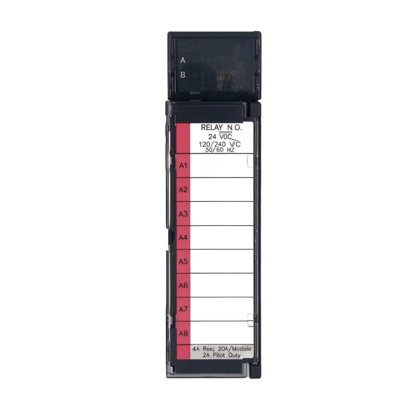
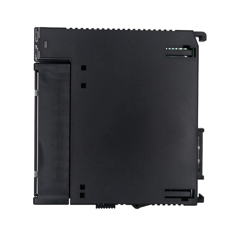
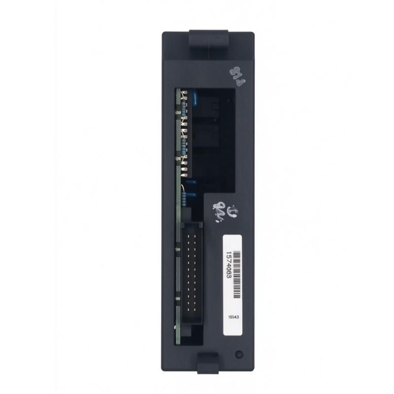
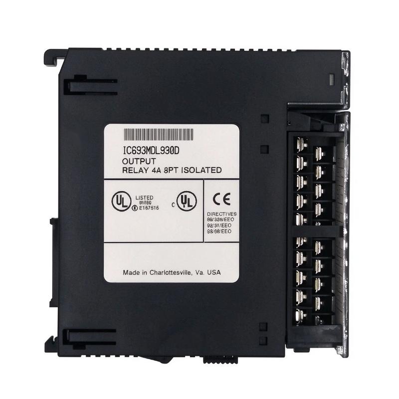
- GE
- IC693MDL930D
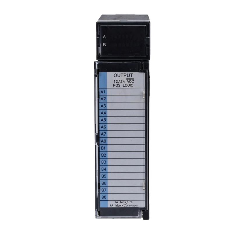
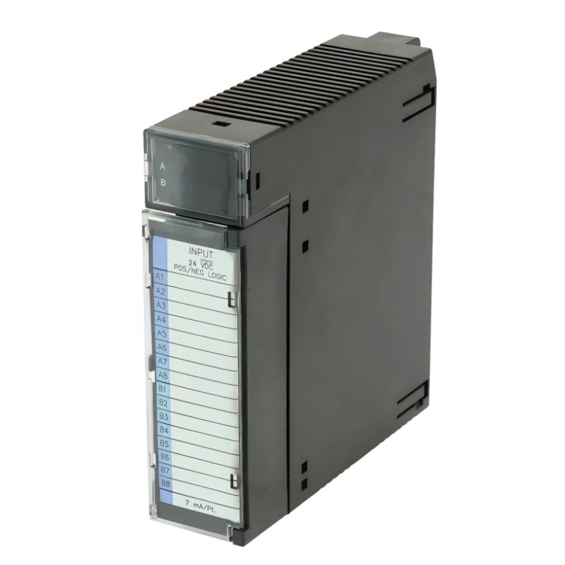
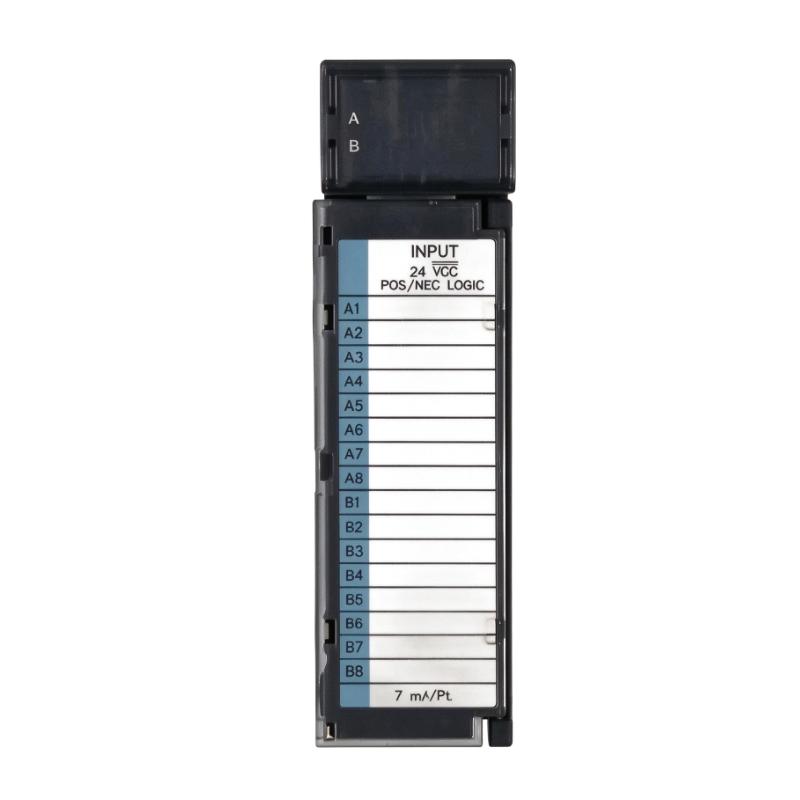
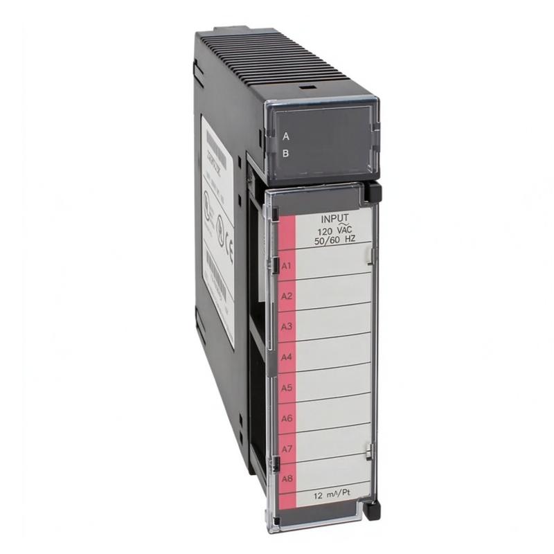
- Isolation Relay Output Module
- USA
- 150 × 55 × 100 mm
- 0.45 kg
- Xiamen, China
- New & In Stock
- T/T, PayPal, Western Union
- 1 Year
- 1-3 Working Days
- DHL, UPS, TNT, FedEx and EMS.
- 24-Hour Service
- COO
- 2
Our advantage

Global Logistics
We have a 10-year logistics and express cooperation agreement, so our products can be shipped to any place in the world.

Brand new and original
Our products are imported in bulk from the place of origin. Because of the cooperative relationship, our products are all original and 100% new.

24-hour service
We provide 7*24 hours service to our customers. We will be there whenever you need us.

Price advantage
All our products are priced very favorably because we have our own warehouse and supply.
| Company Information | |||
| [email protected] | |||
| Mobile | +8615980777398 | ||
| +8615980777398 | |||
| 15980777398 |
Product Overview
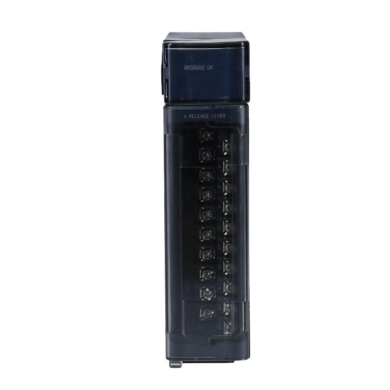
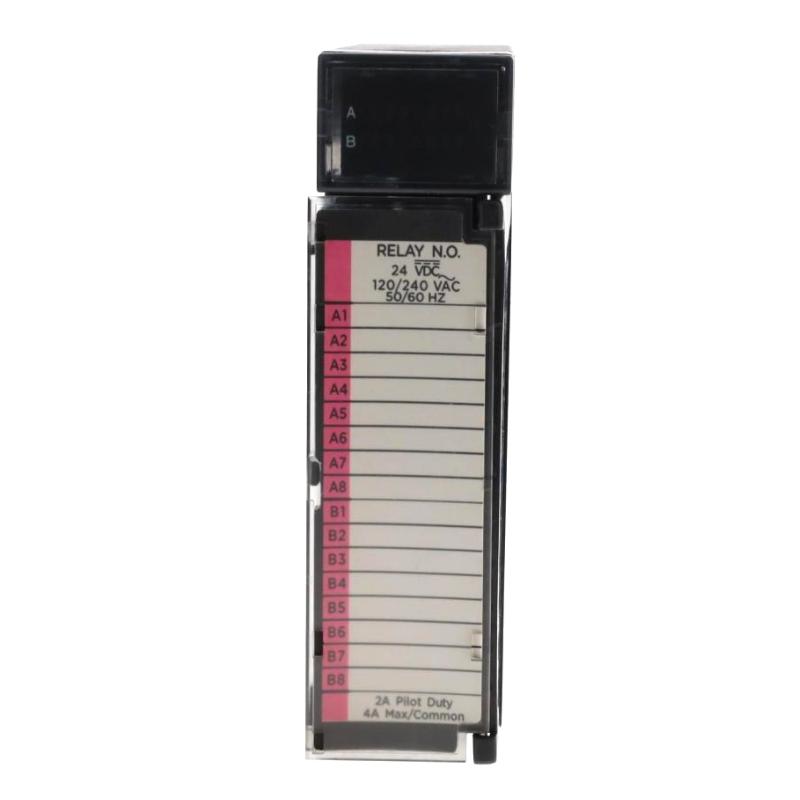
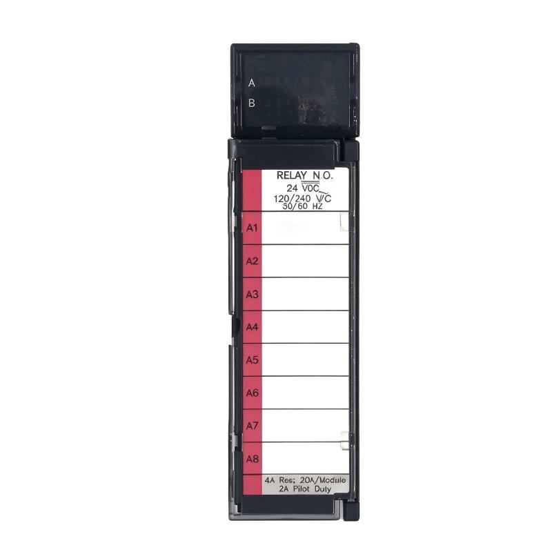
The GE Fanuc IC693MDL930D Isolation Relay Output Module is an industrial digital output module designed for use in GE Fanuc Series 90-30 Programmable Logic Controller (PLC) systems. It provides isolated relay switching channels that allow a PLC to control external electrical loads, including contactors, solenoids, indicator lamps, and other industrial devices.
In an automated control system, output modules provide the interface between the PLC’s internal logic and external field equipment. The controller processes program instructions and determines when an output should be activated. The relay output module then switches the corresponding external circuit, allowing the PLC to control equipment according to the production sequence.
The IC693MDL930 series provides eight normally open relay output circuits. Each output point has a switching capacity of up to 4 A for resistive loads, subject to the specified voltage, load, and temperature limitations. Individual isolation between output points helps separate field circuits and supports applications involving different electrical loads.
The module supports AC and DC field circuits within its specified operating ranges. The user supplies the external power required by the connected field devices; the module’s relay contacts perform the switching function rather than directly generating the field supply voltage.
The IC693MDL930D is relevant to maintenance and spare-parts requirements for existing Series 90-30 installations. Before ordering, users should verify the complete catalog number, hardware revision, terminal arrangement, and compatibility with the installed PLC baseplate.
Technical Specifications
| Parameter | Specification |
|---|---|
| Brand | GE Fanuc |
| Product Series | Series 90-30 |
| Model | IC693MDL930D |
| Product Type | Isolation Relay Output Module |
| Module Function | Discrete Relay Output |
| Output Type | Electromechanical Relay |
| Contact Configuration | Normally Open (N.O.) |
| Number of Outputs | 8 |
| Maximum Resistive Load Current | 4 A per output |
| Pilot Duty Rating | 2 A per output |
| Operating Voltage, DC | 5–30 V DC |
| Operating Voltage, AC | 5–250 V AC |
| AC Frequency | 50/60 Hz |
| Isolation | 1500 V between field side and logic side; 500 V between groups |
| Minimum Load | 10 mA |
| Maximum Inrush Current | 5 A |
| Maximum On Response Time | 15 ms |
| Maximum Off Response Time | 15 ms |
| Output Status | Individual LED indicators |
| Output Fuses | No onboard output fuses |
| PLC Platform | GE Fanuc Series 90-30 |
| Dimensions Provided | 150 × 55 × 100 mm |
| Weight Provided | 0.45 kg |
Specifications are based on the IC693MDL930 series documentation. Confirm suffix-specific hardware details and the actual unit’s dimensions and weight before ordering.
Function and Working Principle
The IC693MDL930D performs discrete output switching through electromechanical relay contacts. It receives output commands from the PLC backplane and changes the state of the corresponding relay circuits.
1. Relay-Based Output Switching
Each output channel uses a normally open relay contact. When the PLC activates an output, the corresponding relay changes state and closes its contact, completing the external field circuit.
When the output is deactivated, the relay returns to its normally open state and interrupts the circuit.
This arrangement allows a PLC to control external equipment without directly supplying the operating voltage to the field load through its internal logic circuitry.
2. Eight Independent Output Points
The IC693MDL930 series provides eight isolated relay outputs. Each point can be assigned to a different field device or control function.
Typical examples include:
- Switching a motor starter control circuit.
- Activating an industrial solenoid valve.
- Controlling an indicator lamp.
- Operating an interposing relay.
- Enabling auxiliary equipment.
- Switching selected alarm and signaling circuits.
The individual output arrangement allows engineers to organize multiple field-control functions within one PLC module.
3. Electrical Isolation
Electrical isolation is an important feature of relay output modules. The IC693MDL930 documentation specifies isolation between the field side and logic side, as well as isolation between output groups.
This arrangement helps reduce the direct electrical interaction between the PLC backplane and external field circuits. It is particularly useful where different devices operate at different permitted AC or DC voltage levels.
Isolation does not replace proper grounding, circuit protection, or safe wiring practices. All connected circuits must remain within the module’s electrical ratings.
4. AC and DC Load Switching
The module supports specified AC and DC operating voltage ranges. This gives engineers flexibility when connecting different types of field devices.
For AC loads, the external supply must operate within the documented voltage and frequency limits. For DC loads, the connected circuit must remain within the permitted DC range.
The actual switching capacity depends on the load type. Resistive loads and inductive loads have different electrical characteristics, so engineers must evaluate contact current, inrush current, and switching frequency before connecting a device.
5. LED Output Status Indication
Individual LED indicators provide visual information about output status. During commissioning and maintenance, technicians can use these indicators to identify which output points are commanded on.
The LEDs provide a convenient diagnostic reference, but they do not independently confirm that the external device has physically operated. For critical equipment, field feedback sensors or auxiliary contacts may be needed to verify actual device status.
Role in Industrial Control Systems
The IC693MDL930D functions as the output interface between the PLC program and external electrical equipment. It allows the controller to execute automatic sequences by switching connected field circuits.
PLC Output Control
The Series 90-30 PLC processes input signals and program logic to determine when output points should be activated.
For example, a controller may receive a signal from a position sensor, evaluate the machine sequence, and activate a relay output to operate a solenoid valve. The output module carries out the electrical switching required by that command.
Machine Control
In manufacturing machinery, relay outputs can operate auxiliary devices such as contactors, valves, warning lamps, and control relays.
The eight output points allow multiple functions to be organized within one module. This can simplify control-panel wiring and make output assignments easier to maintain.
Process Automation
In process-control installations, the module may be used to switch discrete field equipment according to operating conditions.
For example, a PLC may activate a valve when a tank reaches a programmed level or switch an alarm circuit when a monitored condition falls outside its permitted range.
The module performs the switching operation, while the PLC program determines the control sequence.
Maintenance and System Expansion
The IC693MDL930 series is part of the established GE Fanuc Series 90-30 platform. It may be encountered in existing production facilities where the original PLC architecture remains in service.
For maintenance teams, an accurately identified replacement output module can help restore discrete control functions without requiring an immediate redesign of the entire automation system.
Industrial Applications
1. Manufacturing Machinery
Manufacturing equipment uses discrete output signals to control different machine functions. The IC693MDL930D can switch compatible relay loads such as contactors, indicator lamps, and auxiliary control circuits.
Its eight output points allow several machine-control functions to be managed through one module.
2. Solenoid Valve Control
Solenoid valves are widely used in pneumatic and hydraulic systems. A PLC can activate a relay output to energize a compatible valve circuit and control the movement of cylinders or other actuators.
The valve coil’s voltage, current, inrush characteristics, and suppression requirements must be checked before connection.
3. Motor Starter Control
The module can be used to switch suitable motor starter control circuits. A PLC output command can energize a contactor coil, allowing the starter to control a motor’s power circuit.
The relay output should not be assumed to directly switch a motor’s main power. The contactor and its protective devices must be selected for the motor and application.
4. Alarm and Indication Systems
Industrial facilities use warning lamps, audible alarms, and status indicators to communicate equipment conditions.
The IC693MDL930D can control compatible indicator circuits through its relay contacts. Individual LED status indicators also help technicians observe the module’s output state during troubleshooting.
5. Packaging and Material Handling
Packaging machinery and conveyor systems often require discrete switching for gates, stops, diverters, and auxiliary devices.
The module can be used to operate compatible control circuits according to PLC logic, helping coordinate different machine functions.
6. Process Automation Equipment
In process installations, discrete outputs may be used to control valves, auxiliary pumps through starter circuits, and alarm devices.
The module’s isolated relay contacts provide a flexible interface for suitable AC and DC field loads within the specified electrical limits.
Installation and System Integration
Correct installation is essential for reliable operation and protection of the PLC system.
1. Verify PLC Compatibility
Confirm that the module is intended for the installed GE Fanuc Series 90-30 system. The IC693MDL930 documentation identifies compatibility with the Series 90-30 PLC platform and installation in supported I/O slots.
Before installation, check the baseplate type, available slot, module revision, and system documentation.
2. Check Field Circuit Ratings
Before wiring, confirm that every connected load operates within the module’s specified voltage and current limits.
The documented operating ranges are 5–30 V DC and 5–250 V AC. The maximum resistive load current is 4 A per output, while pilot-duty loads have a lower specified rating.
Inductive loads may produce electrical transients when switched. Appropriate suppression and protection should be considered according to the connected device and installation design.
3. External Power Supply
The module’s relay contacts switch external field circuits. The user must provide the AC or DC power required by the connected devices.
Verify the external supply voltage, polarity where applicable, circuit protection, and wiring arrangement before energizing the system.
4. Terminal Wiring
Connect each field load to its assigned output terminal according to the module wiring diagram. Clearly label field conductors and output assignments to simplify maintenance.
The IC693MDL930 series uses individual isolated output circuits. Follow the exact terminal layout and common-terminal arrangement shown in the applicable hardware documentation.
5. Output Protection
The module does not have onboard output fuses. Appropriate external protection should therefore be included in the field circuit design.
Select protective devices according to the connected load, conductor rating, and applicable electrical regulations. Do not exceed the module’s specified current and voltage limits.
6. Commissioning and Functional Testing
After installation, inspect wiring and verify the external power supply before testing the outputs.
Use the PLC program or approved commissioning procedure to activate each output point individually. Check the corresponding LED indicator and verify that the connected field device responds correctly.
Record output assignments and test results for future maintenance.
7. Hot-Swap Precautions
The published IC693MDL930 documentation warns against inserting or removing the module while the backplane is energized. Hot insertion or removal can damage the module or other system components.
Always follow the PLC system’s approved shutdown, isolation, and module replacement procedures.
Compatible System Components
| Component | Function | Integration Considerations |
|---|---|---|
| GE Fanuc Series 90-30 CPU | Executes PLC logic and controls output commands | Confirm CPU and system configuration |
| Series 90-30 baseplate | Provides module mounting and backplane connections | Verify supported I/O slot |
| Digital input module | Receives field signals from sensors and switches | Used for input feedback and machine conditions |
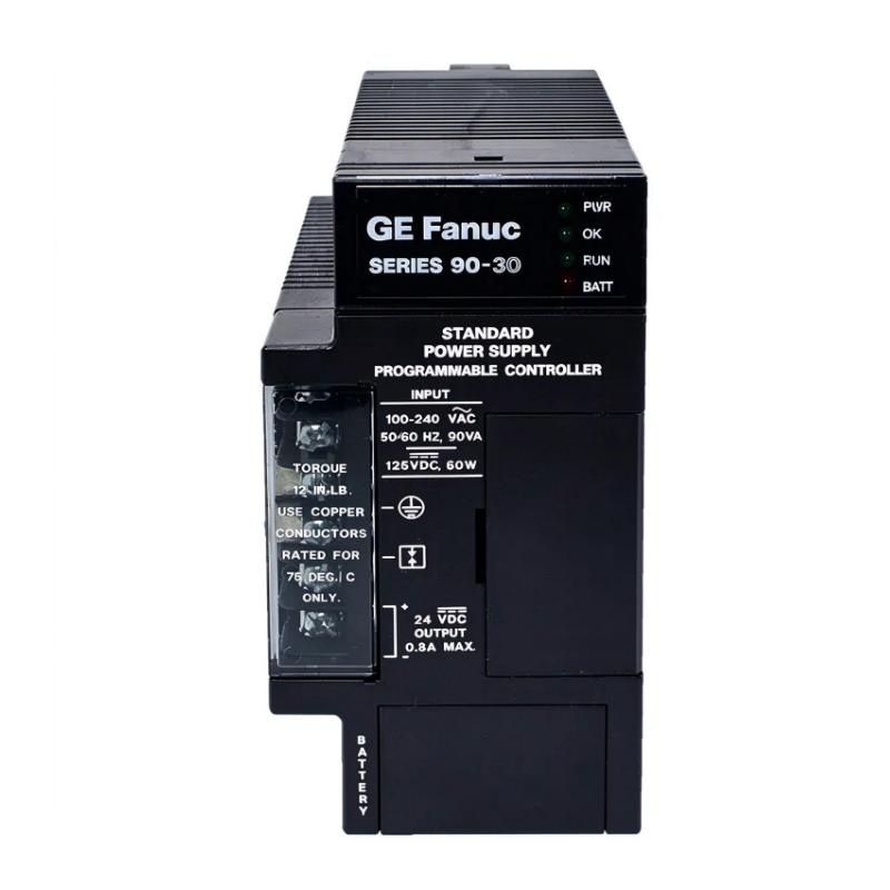
| Power supply module | Supplies the PLC system | Confirm backplane power requirements |
| External field power supply | Powers connected AC or DC loads | Match the voltage and current requirements |
| Contactors | Switch motor power circuits | Use suitable contactor coils and protection |
| Solenoid valves | Control pneumatic or hydraulic flow | Verify coil ratings and suppression requirements |
| Indicator lamps | Provide visual equipment status | Match lamp voltage and current |
| Interposing relays | Provide additional switching or interface functions | Select according to the field circuit |
| Terminal blocks | Organize field wiring | Follow the module’s wiring diagram |
The listed components are examples of equipment that may be used in a complete Series 90-30 control installation. They are not necessarily supplied with the IC693MDL930D.
Alternative Models and Replacement Considerations
When replacing an IC693MDL930D, the most important considerations are the number of output points, contact configuration, electrical ratings, isolation, and PLC compatibility.
| Alternative Model | Product Description | Key Difference |
|---|---|---|
| IC693MDL930 | Isolated relay output module | Eight normally open outputs, 4 A resistive rating |
| IC693MDL916 | Isolated relay output module | Sixteen normally open outputs, 4 A rating |
| IC693MDL931 | Isolated relay output module | Eight outputs with different contact configuration and higher current rating |
| IC693MDL940 | Relay output module | Sixteen normally open outputs, 2 A rating |
| IC694MDL930 | Related RX3i / Series 90-30 relay output module | Verify platform and hardware compatibility |
These models should not be treated as automatic substitutes. Differences in output count, terminal arrangement, contact configuration, and current rating can affect wiring and PLC configuration.
Before purchasing a replacement, check:
- Complete catalog number and suffix.
- Hardware revision.
- Number of output points.
- Normally open or normally closed contact arrangement.
- AC and DC operating voltage.
- Maximum resistive and pilot-duty current.
- Isolation specifications.
- Terminal block and wiring compatibility.
- Baseplate and PLC platform compatibility.
- Module installation and removal requirements.
A replacement module should be selected using the original system documentation and the actual installed hardware as references.
Key Advantages
Eight Isolated Relay Outputs
The module provides eight normally open relay output points for controlling compatible external devices.
AC and DC Switching Capability
Its specified operating voltage ranges support a variety of AC and DC field circuits, subject to the module’s electrical limits.
Individual Output Isolation
Isolation between field and logic circuits helps separate PLC electronics from external field wiring.
4 A Resistive Switching Rating
Each output point has a maximum resistive load switching capacity of 4 A, subject to the manufacturer’s operating conditions.
LED Status Indication
Individual indicators provide a visual reference for output status during commissioning and troubleshooting.
Series 90-30 Integration
The module is designed for the GE Fanuc Series 90-30 PLC platform, making it relevant to existing installations that continue to use this control architecture.
Technical FAQs
1. What is the GE IC693MDL930D?
The IC693MDL930D is identified as an isolation relay output module for industrial PLC applications. The IC693MDL930 series provides eight normally open relay output circuits for GE Fanuc Series 90-30 systems.
2. How many output points does the module provide?
The IC693MDL930 series provides eight isolated relay output points.
3. What is the maximum output current?
The documented maximum resistive load current is 4 A per output point. Pilot-duty loads have a lower specified limit of 2 A per output.
4. What voltage range does the module support?
The documented operating range is 5–30 V DC or 5–250 V AC at 50/60 Hz. The actual connected load must remain within the applicable electrical ratings.
5. Are the relay outputs normally open or normally closed?
The IC693MDL930 series uses normally open relay contacts. The contacts close when the corresponding relay output is activated.
6. Does the module provide its own field power?
No. The user must supply the AC or DC power required by the connected field devices. The module provides the relay switching contacts.
7. Does the module have built-in output fuses?
No. The published documentation states that the module does not include output fuses. External circuit protection should be selected according to the connected loads and wiring.
8. Can it control solenoid valves?
Yes, it can switch compatible solenoid valve circuits when their voltage, current, and load characteristics remain within the module’s ratings. Appropriate suppression may be necessary for inductive loads.
9. Can the module be replaced while the PLC is powered?
The published IC693MDL930 documentation warns against hot insertion and removal. Follow the approved shutdown and isolation procedure before replacing the module.
10. What should be checked before purchasing?
Verify the complete catalog number, hardware revision, output specifications, physical condition, terminal arrangement, and compatibility with the existing Series 90-30 installation.
Procurement and Maintenance Recommendations
When sourcing the GE Fanuc IC693MDL930D, confirm the complete catalog number and revision shown on the module label. This is particularly important for legacy PLC equipment, where hardware revisions and terminal configurations may affect replacement decisions.
For new, surplus, or refurbished units, request clear photographs of the front label, terminals, and module condition. Where possible, confirm that the output channels have been tested and that the module has no visible signs of overheating, corrosion, or physical damage.
During maintenance, inspect the terminal connections, external field wiring, circuit protection, and connected loads. Relay contacts are electromechanical components and can experience wear over time, particularly when switching inductive loads or operating under demanding conditions.
Keep a record of PLC output assignments, connected devices, field supply voltages, and maintenance history. This information can simplify fault diagnosis and reduce replacement errors.
Because the Series 90-30 platform is a legacy automation system, it is also advisable to maintain an inventory of critical spare modules and document a longer-term migration strategy where appropriate.
Conclusion
The GE Fanuc IC693MDL930D Isolation Relay Output Module is intended for discrete output control in industrial PLC systems. The IC693MDL930 series provides eight normally open relay output circuits, individual output isolation, LED status indication, and support for specified AC and DC field loads.
With a maximum resistive switching rating of 4 A per point, the module can control compatible devices such as contactors, solenoids, and indicator lamps. Correct voltage selection, external circuit protection, wiring, and PLC compatibility checks are essential for dependable operation.
For maintenance and replacement projects, verifying the complete catalog number and hardware revision helps ensure that the selected module matches the requirements of the existing GE Fanuc Series 90-30 control system.