

ProductPRODUCT
Featured products
Contact Us
- GE
- IC693MDL645E
- Positive/Negative Logic Input Module
- USA
- 142 x 30 x 130 mm
- 0.45 kg
- Xiamen, China
- New & In Stock
- T/T, PayPal, Western Union
- 1 Year
- 1-3 Working Days
- DHL, UPS, TNT, FedEx and EMS.
- 24-Hour Service
- COO
- 2
Our advantage

Global Logistics
We have a 10-year logistics and express cooperation agreement, so our products can be shipped to any place in the world.

Brand new and original
Our products are imported in bulk from the place of origin. Because of the cooperative relationship, our products are all original and 100% new.

24-hour service
We provide 7*24 hours service to our customers. We will be there whenever you need us.

Price advantage
All our products are priced very favorably because we have our own warehouse and supply.
| Company Information | |||
| [email protected] | |||
| Mobile | +8615980777398 | ||
| +8615980777398 | |||
| 15980777398 |
Product Overview
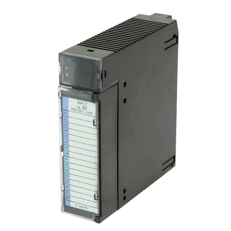
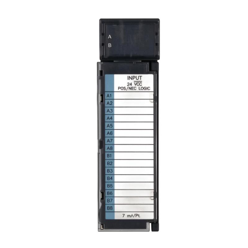
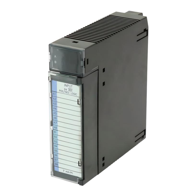
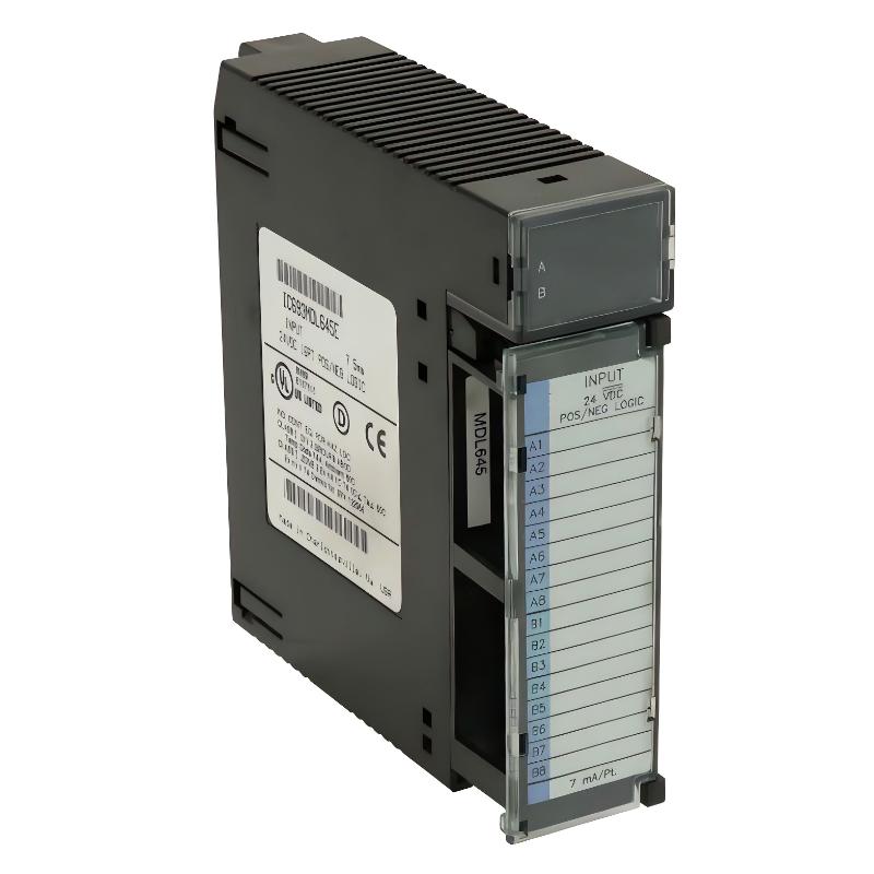
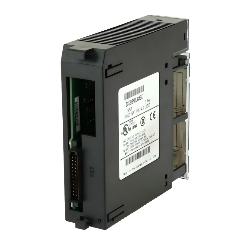
The GE IC693MDL645E Positive/Negative Logic Input Module is a 24 V DC discrete input module designed for the GE Fanuc Series 90-30 Programmable Logic Controller (PLC) platform. It provides 16 digital input points for receiving status signals from industrial field devices and transferring those signals to the PLC CPU for processing.
In industrial automation systems, digital input modules form an important connection between field equipment and the control system. They allow a PLC to monitor the operating states of sensors, switches, pushbuttons, and other devices. The controller can then use this information to execute machine sequences, manage interlocks, detect equipment conditions, and coordinate production processes.
The IC693MDL645E supports both positive and negative logic input characteristics. This flexibility allows it to interface with a range of compatible 24 V DC field devices. Its input voltage range is 0 to +30 V DC, making it suitable for applications using standard 24 V DC control signals.
The module provides 16 input points arranged in one group with a single common connection. Each point has a corresponding LED indicator to help maintenance personnel identify the input status during commissioning and troubleshooting. The module also provides electrical isolation between the field side and the PLC logic side.
Designed for installation in a GE Fanuc Series 90-30 PLC rack, the IC693MDL645E is used in manufacturing equipment, material-handling systems, packaging machinery, and other automated processes that require dependable discrete signal acquisition.
For replacement and maintenance projects, it is important to verify the complete model number, hardware revision, terminal arrangement, and PLC system compatibility before purchasing.
Technical Specifications
| Parameter | Specification |
|---|---|
| Brand | GE Fanuc |
| Manufacturer | GE |
| Model | IC693MDL645E |
| Product Series | Series 90-30 |
| Product Type | Positive/Negative Logic Input Module |
| Module Function | Digital / Discrete Input |
| Rated Input Voltage | 24 V DC |
| Input Voltage Range | 0 to +30 V DC |
| Number of Input Points | 16 |
| Input Configuration | One group with a single common |
| Input Current | 7 mA typical at rated voltage |
| On-State Voltage | 11.5 to 30 V DC |
| Off-State Voltage | 0 to +5 V DC |
| Minimum On-State Current | 3.2 mA |
| Maximum Off-State Current | 1.1 mA |
| On Response Time | 7 ms typical |
| Off Response Time | 7 ms typical |
| Field-to-Logic Isolation | 1500 V |
| 5 V Backplane Current | 80 mA |
| 24 V Power Consumption | 125 mA |
| Status Indicators | 16 LED indicators |
| Installation Platform | GE Fanuc Series 90-30 PLC |
| Dimensions Provided | 142 × 30 × 130 mm |
| Weight Provided | 0.45 kg |
Note: Dimensions and weight are the supplied listing values. Confirm the physical module and packaging measurements before using them for installation or shipping calculations.
Function and Working Principle
The main function of the IC693MDL645E is to receive discrete electrical signals from industrial field devices and make their logical states available to the Series 90-30 PLC.
A discrete input normally represents one of two conditions, such as ON or OFF, open or closed, or detected or not detected. The module processes these electrical conditions so that the PLC can interpret them as digital input states.
1. Positive and Negative Logic Input
The IC693MDL645E supports positive and negative logic characteristics. This allows the module to work with compatible field-device wiring arrangements using different signal conventions.
In a positive-logic arrangement, an active input is generally represented by a voltage level that produces the logical ON state. In a negative-logic arrangement, the field circuit is configured according to the corresponding negative-logic signal convention.
The exact wiring arrangement must follow the module’s field-wiring diagram. Engineers should verify the signal polarity, common connection, and field power supply before connecting devices.
2. Sixteen-Point Signal Acquisition
The module provides 16 discrete input channels. These inputs can monitor multiple field devices within a machine or process.
Typical connected devices include:
- Pushbuttons and selector switches.
- Mechanical limit switches.
- Proximity sensors.
- Equipment status contacts.
- Auxiliary relay contacts.
- Compatible electronic switching devices.
Each input point is assigned a corresponding PLC input address. The PLC program reads the input states and uses them to determine the next control action.
3. Input Signal Conditioning
The module accepts input voltages within its specified range and processes the electrical signals before presenting their logical states to the controller.
Its input characteristics include an on-state voltage range of 11.5 to 30 V DC and an off-state voltage range of 0 to +5 V DC. These thresholds help distinguish valid ON and OFF conditions.
Correct signal levels are important. A field device that produces an unstable or insufficient voltage may cause unreliable input recognition.
4. Electrical Isolation
The IC693MDL645E provides 1500 V isolation between the field side and the PLC logic side.
Isolation helps reduce the direct transfer of electrical disturbances between external field circuits and the controller’s internal logic circuitry. It is particularly relevant in industrial installations where sensors, switches, and other field devices may operate in electrically noisy environments.
Isolation does not replace proper grounding, surge protection, or correct wiring practices.
5. LED Status Indication
The module has 16 green LED indicators arranged in two rows. The upper row identifies input points A1 through A8, while the lower row identifies B1 through B8.
These indicators provide a convenient visual reference for checking input conditions. During troubleshooting, technicians can compare the field-device state with the corresponding LED and PLC input status.
This makes it easier to identify wiring problems, inactive sensors, incorrect signal polarity, or unexpected input conditions.
Role in Industrial Control Systems
The IC693MDL645E functions as the digital signal interface between field equipment and a GE Fanuc Series 90-30 PLC.
It does not independently control motors or execute machine sequences. Instead, it provides the input information that the PLC uses to make control decisions.
PLC Signal Processing
When a field device changes state, the corresponding input channel detects the electrical condition and makes the input status available to the PLC.
The CPU can then process the signal through its control program. For example, a limit switch may indicate that a machine component has reached its required position. The PLC can use that information to stop one movement and initiate the next operation.
Machine Interlocking
Discrete input signals are often used to confirm that equipment is in a permitted operating condition.
The module can monitor compatible status contacts and switches that form part of a machine’s interlock logic. The PLC program can use these signals to prevent an operation from proceeding when required conditions are not satisfied.
The module itself is not a safety-rated device and should not be used as a substitute for a properly designed safety system.
Process Monitoring
The module can collect operating states from multiple devices across a production process. These signals may indicate whether a machine is running, whether a guard contact is closed, or whether a material-handling station has detected a product.
The PLC can use the input information for sequence control, alarm generation, and production monitoring.
Maintenance and Diagnostics
The 16 LED indicators help technicians identify the status of individual input channels. This is useful when checking sensor wiring, diagnosing signal interruptions, or comparing physical device states with PLC program information.
Industrial Applications
The GE IC693MDL645E is suitable for industrial systems that require 24 V DC positive/negative logic discrete input monitoring.
1. Manufacturing Machinery
Manufacturing machines use numerous switches and sensors to monitor operating conditions. The IC693MDL645E can receive compatible signals from position switches, pushbuttons, and equipment status contacts.
The PLC uses these signals to coordinate machine sequences and monitor operating states.
2. Conveyor and Material-Handling Systems
Conveyor systems rely on discrete signals to detect products, confirm transfer positions, and monitor equipment conditions.
The module can receive signals from compatible photoelectric sensors, proximity switches, and limit switches. The PLC can then use this information to coordinate conveyor movement and product handling.
3. Packaging Equipment
Packaging machinery uses digital signals to detect product presence, confirm component positions, and monitor the status of different operating stations.
The 16 input channels provide a convenient interface for collecting multiple machine signals within a Series 90-30 control system.
4. Assembly Lines
Automated assembly equipment often uses switches and sensors to confirm that parts are correctly positioned before the next operation begins.
The module can transfer these discrete signals to the PLC, allowing the control program to coordinate assembly steps and detect abnormal conditions.
5. Pumping and Auxiliary Equipment
Industrial pumping systems may use discrete status contacts to monitor motor starters, pressure-switch conditions, valve limit switches, and equipment availability.
The IC693MDL645E can collect compatible 24 V DC signals for PLC-based monitoring and sequencing.
6. General Process Automation
In process-control installations, discrete inputs are used alongside analog measurements to provide a more complete picture of equipment operation.
The module can monitor binary field conditions and provide the PLC with information needed for alarms, interlocks, and process sequences.
Installation and System Integration
Correct installation is essential for reliable input detection and long-term module operation.
1. Verify PLC Compatibility
The IC693MDL645E is designed for the GE Fanuc Series 90-30 PLC platform. It can be installed in a compatible 5-slot or 10-slot Series 90-30 baseplate.
Before installation, verify the rack configuration, available I/O slot, module revision, and system documentation.
Do not assume that a module with a similar catalog number is interchangeable with every Series 90-30 or RX3i system.
2. Check the Field Supply Voltage
The module is rated for 24 V DC input signals and accepts an input range of 0 to +30 V DC.
Confirm that connected field devices operate within the specified range. Check the voltage at the module terminals under actual operating conditions rather than relying only on the power supply’s nominal rating.
3. Confirm Positive or Negative Logic Wiring
The correct wiring arrangement depends on the type of field device and the required signal convention.
Before connecting the field circuits:
- Review the module’s wiring diagram.
- Identify the common terminal.
- Confirm the field-device output polarity.
- Verify the 24 V DC supply and return connections.
- Check that the signal voltage meets the input thresholds.
Incorrect polarity or common wiring can result in inputs that remain permanently ON or OFF.
4. Connect Field Devices
The module provides 16 input points arranged in one group with a single common. Connect each field device to its assigned input terminal according to the system wiring diagram.
Suitable devices may include pushbuttons, limit switches, and electronic proximity sensors with compatible 24 V DC outputs.
Use appropriate terminal connections and ensure that field wiring is securely installed.
5. Install the Module
Before inserting or removing the module, follow the applicable Series 90-30 installation procedures and isolate power where required.
Ensure that the module is correctly seated in the designated rack slot. Check the terminal block, wiring condition, and module retention before restoring the system.
6. Configure PLC Input Addresses
After physical installation, identify the input addresses assigned to the module in the PLC configuration.
Update or verify the PLC program so that each input is associated with the correct field device. Incorrect address mapping can cause the controller to interpret a sensor signal as a different machine condition.
7. Perform Functional Testing
After wiring and configuration, test each input point individually.
Operate the connected field device and observe the corresponding LED indicator. Confirm that the PLC input status changes as expected.
Testing should include:
- ON-state recognition.
- OFF-state recognition.
- Correct signal polarity.
- Stable input behavior.
- Correct PLC address mapping.
- Expected machine response.
Document the final wiring and PLC configuration for future maintenance.
Compatible System Components
The IC693MDL645E is part of a wider Series 90-30 PLC installation. The following components may be used in a compatible control system.
| Component | Function | Integration Considerations |
|---|---|---|
| GE Fanuc Series 90-30 CPU | Executes PLC control logic | Verify CPU and rack configuration |
| Series 90-30 baseplate | Provides the module mounting and backplane connection | Confirm 5-slot or 10-slot baseplate compatibility |
| Series 90-30 power supply | Supplies system operating power | Check backplane power requirements |
| 24 V DC power supply | Powers compatible field devices | Confirm current capacity and voltage stability |
| Pushbuttons | Provide operator commands | Match contact wiring to the input logic |
| Limit switches | Detect mechanical positions | Verify contact ratings and wiring |
| Proximity sensors | Detect objects without physical contact | Confirm 24 V DC output compatibility |
| Relay contacts | Provide discrete equipment status signals | Verify contact arrangement and circuit voltage |
| PLC programming software | Configures and monitors PLC logic | Confirm compatibility with the installed CPU and software version |
These components are examples of equipment used in a complete control installation. They are not necessarily included with the IC693MDL645E.
Alternative Models and Replacement Considerations
Several Series 90-30 input modules provide related discrete input functions. However, differences in voltage, logic type, channel count, and response time must be considered before replacement.
| Model | Description | Replacement Considerations |
|---|---|---|
| IC693MDL645 | 24 V DC positive/negative logic input, 16 points | Closely related base model; verify revision and exact specifications |
| IC693MDL646 | 24 V DC positive/negative logic input, 16 points, faster filtering | Different response characteristics; verify application timing |
| IC693MDL640 | 24 V DC positive logic input, 16 points | Logic configuration differs |
| IC693MDL641 | 24 V DC negative logic input, 16 points | Logic configuration differs |
| IC693MDL655 | 24 V DC positive/negative logic input, 32 points | Higher point count and different wiring arrangement |
A replacement decision should consider more than the nominal voltage. Check the complete catalog number, hardware revision, wiring diagram, input characteristics, response time, terminal arrangement, and PLC configuration.
Key Advantages
16 Discrete Input Channels
The module provides 16 input points for collecting multiple field signals within a single Series 90-30 PLC slot.
Positive and Negative Logic Support
Its positive/negative logic characteristics provide flexibility when connecting compatible 24 V DC field devices.
Wide Input Voltage Range
The 0 to +30 V DC input range supports standard 24 V DC control signals within the specified operating limits.
Electrical Isolation
The 1500 V field-to-logic isolation helps separate external field circuits from the PLC logic side.
Individual LED Indicators
Each input point has a corresponding LED, making it easier to monitor field signal conditions and troubleshoot wiring.
Series 90-30 Integration
The module is designed for the established GE Fanuc Series 90-30 PLC platform and can be used in compatible rack configurations.
Practical Industrial Signal Monitoring
The module supports common discrete monitoring tasks involving switches, sensors, pushbuttons, and equipment status contacts.
Technical FAQs
1. What is the GE IC693MDL645E?
The IC693MDL645E is a 24 V DC positive/negative logic discrete input module for GE Fanuc Series 90-30 PLC systems. It provides 16 digital input points.
2. What is the rated input voltage?
The rated input voltage is 24 V DC. The specified input voltage range is 0 to +30 V DC.
3. How many input channels does it provide?
The module provides 16 input points arranged in one group with a single common connection.
4. What does positive/negative logic mean?
Positive/negative logic refers to the module’s ability to support compatible positive-logic and negative-logic field wiring arrangements. The correct configuration depends on the field device and the wiring design.
5. What is the input response time?
The typical ON response time is 7 ms, and the typical OFF response time is also 7 ms.
6. Does the module have LED indicators?
Yes. It has 16 green LED indicators arranged in two rows. They show the ON/OFF status of the corresponding input points.
7. What is the isolation rating?
The module provides 1500 V isolation between the field side and the PLC logic side.
8. Which PLC system is compatible with the IC693MDL645E?
It is designed for GE Fanuc Series 90-30 PLC systems. Verify the baseplate, rack configuration, and system documentation before installation.
9. Can it connect directly to proximity sensors?
Yes, provided the sensors have compatible 24 V DC output characteristics and are wired according to the module’s positive/negative logic requirements.
10. What should be checked before purchasing a replacement?
Verify the full model number, hardware revision, input voltage, number of channels, logic configuration, terminal arrangement, physical condition, and PLC compatibility.
Procurement and Maintenance Recommendations
When purchasing the GE IC693MDL645E, confirm that the product label matches the required catalog number. Series 90-30 modules can have similar appearances while differing in input voltage, logic characteristics, channel count, or response time.
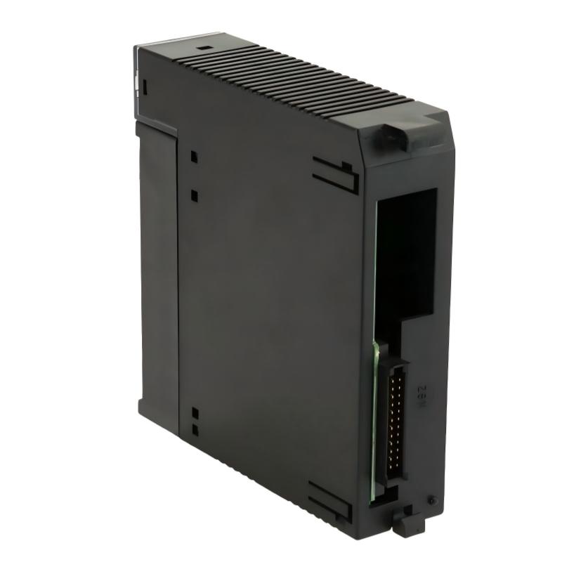
For new, surplus, or refurbished units, request clear photographs of the front label, terminal area, and module condition. Confirm whether the terminal block is included and establish the warranty and return conditions before ordering.
During maintenance, inspect the terminal connections, field wiring, module seating, and LED indicators. Loose connections, damaged conductors, incorrect common wiring, or unstable field power can cause input faults that may initially appear to be PLC hardware problems.
Keep an updated wiring diagram and PLC input-address list. When replacing a module, compare the original wiring with the replacement documentation before reconnecting field devices. Test all 16 channels after installation and confirm that each field signal produces the expected PLC status.
Conclusion
The GE IC693MDL645E Positive/Negative Logic Input Module is a 16-point, 24 V DC discrete input module designed for GE Fanuc Series 90-30 PLC systems. It supports positive and negative logic input arrangements, accepts signals within a 0 to +30 V DC range, and provides 1500 V isolation between field and logic circuits.
With individual LED indicators and compatibility with common industrial switching devices, the module provides a practical interface for collecting machine and process status signals. For maintenance and replacement applications, verifying the complete model number, input characteristics, wiring configuration, and PLC rack compatibility is essential for reliable operation.