

ProductPRODUCT
Featured products
Contact Us
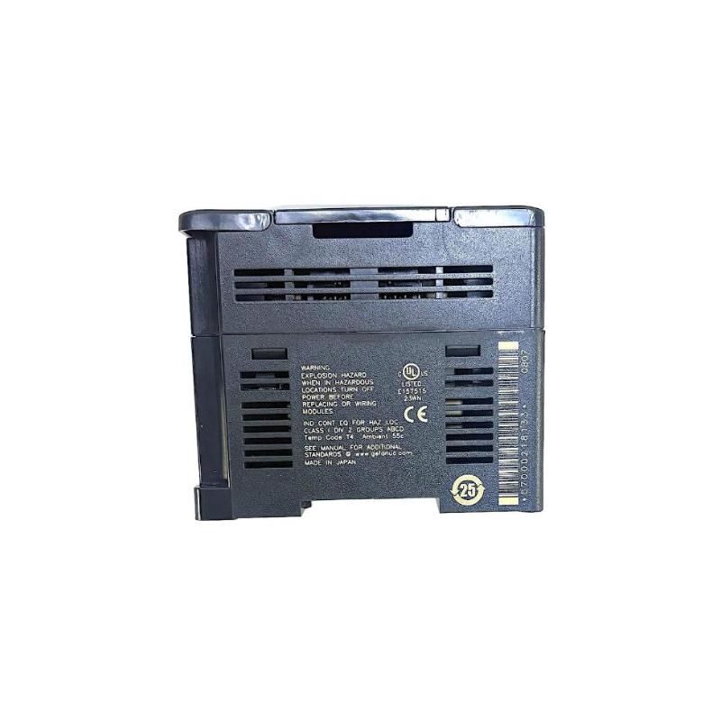
- GE
- IC200UEO116
- VersaMax Miniature Expansion Module
- USA
- 95 x 90 x 76 mm
- 1.36 kg
- Xiamen, China
- New & In Stock
- T/T, PayPal, Western Union
- 1 Year
- 1-3 Working Days
- DHL, UPS, TNT, FedEx and EMS.
- 24-Hour Service
- COO
- 53
Our advantage

Global Logistics
We have a 10-year logistics and express cooperation agreement, so our products can be shipped to any place in the world.

Brand new and original
Our products are imported in bulk from the place of origin. Because of the cooperative relationship, our products are all original and 100% new.

24-hour service
We provide 7*24 hours service to our customers. We will be there whenever you need us.

Price advantage
All our products are priced very favorably because we have our own warehouse and supply.
| Company Information | |||
| [email protected] | |||
| Mobile | +8615980777398 | ||
| +8615980777398 | |||
| 15980777398 |
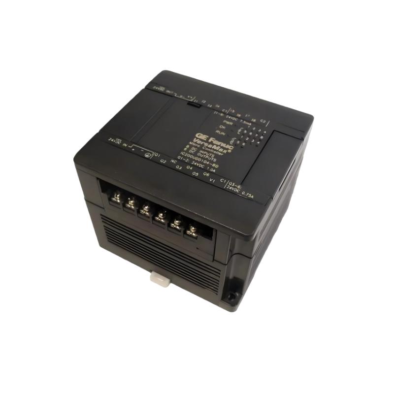
Product Overview
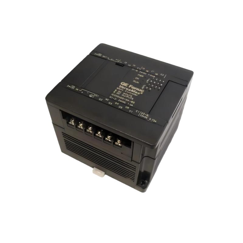
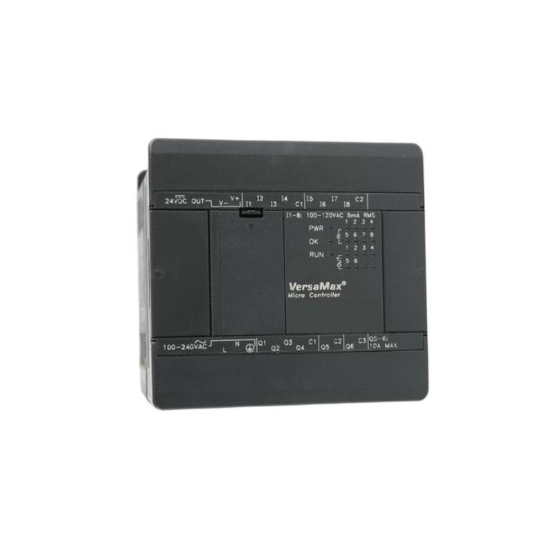
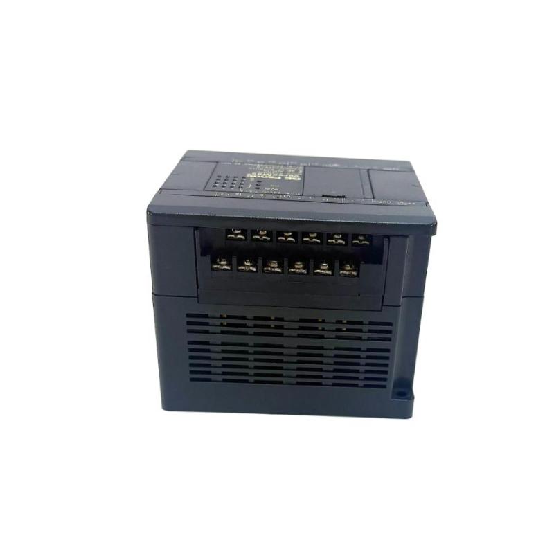
The GE IC200UEO116 VersaMax Miniature Expansion Module is a compact expansion component designed for integration into compatible GE VersaMax industrial automation systems. It is intended to extend the functionality of the control architecture by providing additional system capacity within a modular VersaMax configuration.
In industrial automation, expansion hardware allows a control system to grow as machine requirements increase. Instead of replacing the complete controller, an appropriate expansion module can be integrated into the existing architecture, provided that the controller, power system, communication structure, and application configuration support the additional hardware.
The supplied product information identifies the GE IC200UEO116 as a VersaMax Miniature Expansion Module, with dimensions of 95 × 90 × 76 mm and a weight of 1.36 kg.
Product Information
- Manufacturer: GE
- Product Family: VersaMax
- Model: IC200UEO116
- Product Type: VersaMax Miniature Expansion Module
- Dimensions: 95 × 90 × 76 mm
- Weight: 1.36 kg
- Application: Industrial Automation
- System Role: Expansion Module
- Installation Type: Modular Control System
The IC200UEO116 should be installed only in a compatible VersaMax system and configured according to the actual controller and expansion architecture.
Technical Specifications
| Parameter | Specification |
|---|---|
| Manufacturer | GE |
| Product Family | VersaMax |
| Model Number | IC200UEO116 |
| Product Type | Miniature Expansion Module |
| Dimensions | 95 × 90 × 76 mm |
| Weight | 1.36 kg |
| Application | Industrial Automation |
| System Role | System Expansion |
| Architecture | Modular Control System |
| Installation | VersaMax System |
The dimensions and weight in this table follow the product information supplied for this article.
Function and Working Principle
The IC200UEO116 is used as an expansion component within a compatible VersaMax control architecture.
A simplified system structure can be represented as:
Main VersaMax Controller
↓
Expansion Interface
↓
IC200UEO116
↓
Additional System Hardware
The purpose of this type of module is to provide additional capacity or functionality while retaining the basic control architecture.
A modular expansion arrangement can simplify:
- System scaling
- Additional I/O integration
- Machine upgrades
- Control-system modifications
- Equipment modernization
- Maintenance
- Hardware replacement
The actual capabilities available through the IC200UEO116 depend on the complete VersaMax configuration in which it is installed. The controller, expansion hardware, power arrangement, software configuration, and connected modules should therefore be evaluated as one system.
Role in Industrial Control Systems
The IC200UEO116 can form part of a layered industrial automation architecture.
A typical structure is:
Sensors and Field Devices
↓
VersaMax I/O
↓
Main Controller
↓
Expansion Architecture
↓
IC200UEO116
↓
Additional Control-System Resources
↓
Machine Equipment
The expansion module allows the automation architecture to be organized into modular sections rather than concentrating all control functions into a single controller assembly.
This approach is useful for systems that need to be expanded during machine development, equipment modernization, or production-line upgrades.
Industrial Applications
Machine Automation
The IC200UEO116 can be incorporated into compatible machine-control systems requiring additional VersaMax expansion capacity.
Production Equipment
Manufacturing equipment can use modular control architecture to integrate additional system functions as production requirements evolve.
Packaging Machinery
Packaging systems often require multiple control modules and can benefit from scalable automation architectures.
Material Handling
Conveyor systems and material-handling equipment can use modular controllers and expansion components to accommodate growing I/O requirements.
OEM Machinery
Machine builders can use modular expansion architectures when designing standardized control panels for different equipment configurations.
Process Equipment
Industrial process equipment may require additional control hardware as sensors, actuators, and auxiliary functions are added.
Installation Guide
1. Confirm the Model
Before installation, verify the exact model number:
GE IC200UEO116
VersaMax Miniature Expansion Module
Do not assume that another VersaMax expansion module can be substituted solely because its enclosure or dimensions appear similar.
Always verify the complete system compatibility.
2. Review the Existing Architecture
Before adding the IC200UEO116, identify:
- Main controller
- Existing expansion modules
- Power modules
- I/O modules
- Communication modules
- Module positions
- Expansion interfaces
- Hardware configuration
- Application program
Creating an accurate hardware list can prevent configuration conflicts during commissioning.
3. Back Up the Existing Application
Before modifying the control system, make a verified backup of:
- PLC application
- Hardware configuration
- I/O configuration
- Communication parameters
- System settings
- Machine-specific configuration
This provides a recovery point if the system needs to be restored after installation.
4. Place the Machine in a Safe Condition
The IC200UEO116 may be part of a control architecture connected to industrial machinery.
Before maintenance:
- Stop automatic operation.
- Place the machine in a safe state.
- Identify connected equipment.
- Isolate hazardous energy as required.
- Follow approved lockout/tagout procedures.
- Verify that unexpected movement cannot occur.
5. Inspect the Expansion Module
Before installation, inspect the IC200UEO116 for:
- Cracks
- Damaged connectors
- Bent terminals
- Corrosion
- Contamination
- Signs of impact
- Loose mechanical components
A damaged module should not be installed.
6. Verify the Mounting Location
Confirm that the selected mounting location provides:
- Correct orientation
- Adequate mechanical support
- Sufficient clearance
- Easy access for maintenance
- Correct interface alignment
- Appropriate cable routing
The supplied dimensions are 95 × 90 × 76 mm, but additional cabinet clearance should be provided for wiring and service access.
7. Verify System Compatibility
Before connecting the module, check the compatibility of:
- Main controller
- Expansion architecture
- Power supply
- Existing modules
- Hardware configuration
- Application software
Do not energize the system until the complete configuration has been reviewed.
8. Install the Module
Position the IC200UEO116 correctly in the applicable VersaMax expansion arrangement.
Check:
- Module orientation
- Mechanical engagement
- Connector alignment
- Mounting security
- Adjacent module clearance
Do not force the module into an incorrectly aligned connector.
9. Check Connections
After installation, inspect the complete expansion assembly.
Verify:
- Module engagement
- Interface connections
- Adjacent modules
- Power connections
- Communication connections where applicable
- Field wiring
A loose interface can produce intermittent system faults.
Commissioning Procedure
Step 1 — Visual Inspection
Inspect the complete control assembly.
Step 2 — Check Mechanical Installation
Confirm that the IC200UEO116 is securely installed.
Step 3 — Verify Power
Check the control-system power supply and confirm that it is stable.
Step 4 — Verify Hardware Configuration
Compare the physical system with the configured system.
Step 5 — Check Module Status
Review controller and module diagnostic information.
Step 6 — Verify Expansion Recognition
Confirm that the control system recognizes the installed expansion hardware as expected.
Step 7 — Test Connected Functions
Test the associated modules and control functions.
Step 8 — Test Communication
Where applicable, verify communication with connected control equipment.
Step 9 — Run the Application
Test the machine under controlled operating conditions.
Step 10 — Return to Production
After successful testing, return the system to normal operation.
Troubleshooting Guide
Problem 1: IC200UEO116 Is Not Recognized
Possible causes include:
- Incorrect installation
- Incorrect module configuration
- Poor connector engagement
- Incompatible hardware
- Power problem
- Module failure
Recommended Checks
- Verify the model number.
- Inspect module installation.
- Check all connectors.
- Verify power.
- Compare the physical hardware with the software configuration.
- Review controller diagnostics.
Problem 2: Controller Reports a Configuration Error
A configuration error may occur when the physical hardware does not match the expected system configuration.
Check:
- Module type
- Module location
- Expansion arrangement
- Controller configuration
- Application configuration
Make sure the actual system corresponds to the intended hardware configuration.
Problem 3: Expansion Functions Are Unavailable
Possible causes include:
- Expansion interface fault
- Incorrect module installation
- Configuration problem
- Power issue
- Fault in connected modules
- Controller problem
Troubleshoot from the main controller outward.
Problem 4: Module Operates Intermittently
Intermittent faults may result from:
- Loose connections
- Mechanical vibration
- Electrical interference
- Power instability
- Temperature
- Contamination
- Connector problems
Inspect the physical installation before replacing the module.
Problem 5: Multiple Connected Modules Stop Working
If several modules fail simultaneously, first check common system elements.
Inspect:
- Power supply
- Expansion interface
- Common wiring
- Controller status
- System configuration
A shared power or interface problem is more likely than multiple independent module failures.
Problem 6: Controller Fault Appears After Installing IC200UEO116
If a controller fault begins immediately after expansion installation, investigate:
- Incorrect module type
- Incorrect hardware configuration
- Poor connector engagement
- Incorrect module arrangement
- Power problem
- Compatibility issue
Compare the system with its previous configuration.
Problem 7: Replacement IC200UEO116 Does Not Work
Check:
- Exact model number
- Installation position
- Module orientation
- Connector engagement
- Controller compatibility
- Hardware configuration
- Power condition
Do not assume that a replacement module is defective before verifying installation and configuration.
Problem 8: System Becomes Unstable After Expansion
Potential causes include:
- Insufficient or unstable power
- Incorrect system configuration
- Electrical interference
- Incorrect expansion architecture
- Communication problems
- Environmental conditions
Record exactly when the instability occurs and which modules are affected.
Problem 9: Fault Remains After Module Replacement
If replacing the IC200UEO116 does not solve the problem, investigate:
- Main controller
- Power supply
- Expansion interface
- Adjacent modules
- Communication equipment
- Application configuration
- Field wiring
- Environmental conditions
This prevents unnecessary replacement of functioning hardware.
Diagnostic Strategy
A structured troubleshooting sequence is:
Power Supply
↓
Main Controller
↓
Expansion Interface
↓
IC200UEO116
↓
Connected Modules
↓
Field Equipment
For configuration-related faults:
Physical Hardware
↔
Hardware Configuration
For intermittent problems:
Connections
→ Power
→ Environment
→ Communication
→ Application
This method allows technicians to isolate problems systematically instead of replacing components without sufficient evidence.
Module Replacement Procedure
Phase 1 — Preparation
- Confirm GE IC200UEO116.
- Verify the replacement module.
- Back up the application.
- Record the existing hardware configuration.
- Document module positions.
- Identify affected equipment.
- Place the machine in a safe condition.
Phase 2 — Removal
- Stop the control system.
- Isolate power as required.
- Verify safe conditions.
- Disconnect applicable connections.
- Remove the existing module carefully.
Phase 3 — Installation
- Inspect the replacement IC200UEO116.
- Confirm the model number.
- Align the module correctly.
- Install it securely.
- Reconnect interfaces.
- Inspect adjacent connections.
Phase 4 — Configuration
- Verify physical hardware.
- Check controller configuration.
- Confirm module position.
- Verify applicable communication settings.
- Review system diagnostics.
Phase 5 — Commissioning
- Restore power.
- Check controller startup.
- Check module status.
- Verify expansion recognition.
- Test connected hardware.
- Test application functions.
- Monitor the system.
- Return the machine to normal operation.
Preventive Maintenance
| Maintenance Item | Recommended Action |
|---|---|
| IC200UEO116 | Inspect physical condition |
| Mounting | Check secure installation |
| Connectors | Inspect engagement |
| Power Supply | Verify stable operation |
| Expansion Interface | Inspect connections |
| Adjacent Modules | Check mechanical alignment |
| Communication | Check applicable connections |
| Cabinet | Keep clean and dry |
| Grounding | Inspect control-system arrangement |
| Application | Maintain a verified backup |
| Configuration | Document system changes |
| Diagnostics | Review recurring faults |
Environmental Considerations
Temperature
Keep the control cabinet within the appropriate operating environment for the installed equipment.
Dust
Prevent excessive dust accumulation around the control system.
Moisture
Protect the module from condensation and excessive humidity.
Vibration
Avoid excessive mechanical vibration that could loosen module or connector connections.
Electrical Noise
Keep sensitive control wiring appropriately separated from high-current switching circuits, motor cables, and other potential sources of electrical interference.
Common Installation Mistakes
Incorrect Module Identification
Do not install a visually similar VersaMax module without confirming the complete model number.
Incorrect Configuration
The software configuration should correspond to the physical hardware.
Loose Connectors
Poor connector engagement can cause intermittent faults.
Insufficient Cabinet Clearance
Although the module itself measures 95 × 90 × 76 mm, additional space is necessary for wiring, ventilation, and maintenance.
Replacing Hardware Without a Backup
Always preserve the existing controller application and configuration before making system modifications.
Ignoring Common System Faults
If several modules fail simultaneously, check shared power and expansion interfaces before replacing individual modules.
Key Advantages
- VersaMax modular architecture
- Compact miniature expansion design
- Suitable for compatible industrial automation systems
- Supports scalable control-system architecture
- Simplifies system expansion
- Facilitates modular maintenance
- Suitable for machine-control applications
- Suitable for OEM equipment
- Supplied dimensions of 95 × 90 × 76 mm
- Supplied weight of 1.36 kg
Technical FAQs
What is the GE IC200UEO116?
The GE IC200UEO116 is identified as a VersaMax Miniature Expansion Module intended for use within a compatible GE VersaMax industrial automation system.
What is the main function of IC200UEO116?
Its main purpose is to provide expansion capability within a compatible VersaMax control architecture.
What are the dimensions of IC200UEO116?
The supplied dimensions are 95 × 90 × 76 mm.
What is the weight of IC200UEO116?
The supplied weight is 1.36 kg.
Why is IC200UEO116 not recognized?
Check module installation, connector engagement, system power, controller compatibility, module configuration, and controller diagnostics.
Can an incorrect hardware configuration cause an expansion fault?
Yes. A mismatch between the physical hardware and the configured hardware can result in system or configuration faults.
Why does the expansion system work intermittently?
Inspect connectors, mounting, vibration, electrical interference, power stability, environmental conditions, and communication connections.
Should the IC200UEO116 be replaced immediately after an expansion fault?
No. First check power, configuration, connectors, controller status, expansion interfaces, and connected modules.
What should be backed up before replacing IC200UEO116?
The controller application, hardware configuration, I/O configuration, communication settings, and other system-specific parameters should be preserved.
How should an IC200UEO116 fault be diagnosed?
Start with the power supply and main controller, then check the expansion interface, module installation, configuration, connected modules, and field equipment.
Can a faulty expansion interface cause the IC200UEO116 to appear defective?
Yes. A communication or interface problem can prevent the controller from recognizing a properly functioning expansion module.
Why do several modules fail at the same time?
When multiple modules become unavailable simultaneously, investigate shared power, expansion interfaces, controller status, and common connections before assuming multiple hardware failures.
Conclusion
The GE IC200UEO116 VersaMax Miniature Expansion Module is a compact component for expanding compatible VersaMax industrial automation systems. The supplied product information specifies dimensions of 95 × 90 × 76 mm and a weight of 1.36 kg.
Successful installation requires correct model identification, compatible VersaMax architecture, secure mechanical installation, reliable interfaces, appropriate configuration, and stable system power.
During commissioning, technicians should verify the physical hardware against the configured system, confirm controller recognition, inspect connected modules, and test the complete application under controlled conditions.
For troubleshooting, a systematic approach should begin with power and the main controller before progressing through the expansion interface, IC200UEO116, connected modules, configuration, communication, and field equipment.
By following structured installation and diagnostic procedures, maintenance personnel can reduce unnecessary component replacement, shorten troubleshooting time, and maintain reliable operation of the VersaMax control system.