

ProductPRODUCT
Featured products



Contact Us
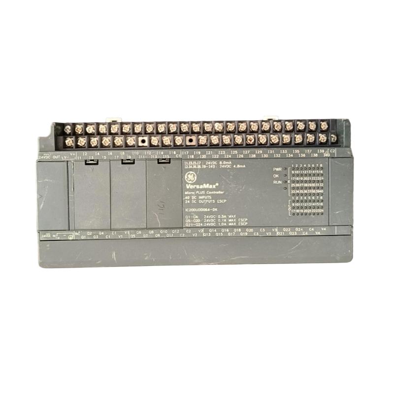
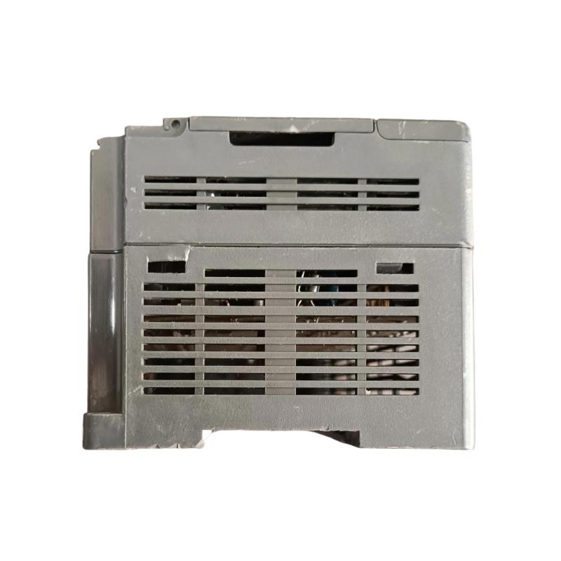
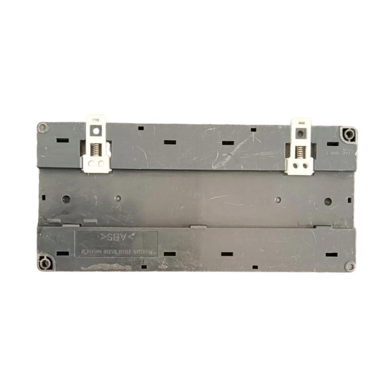
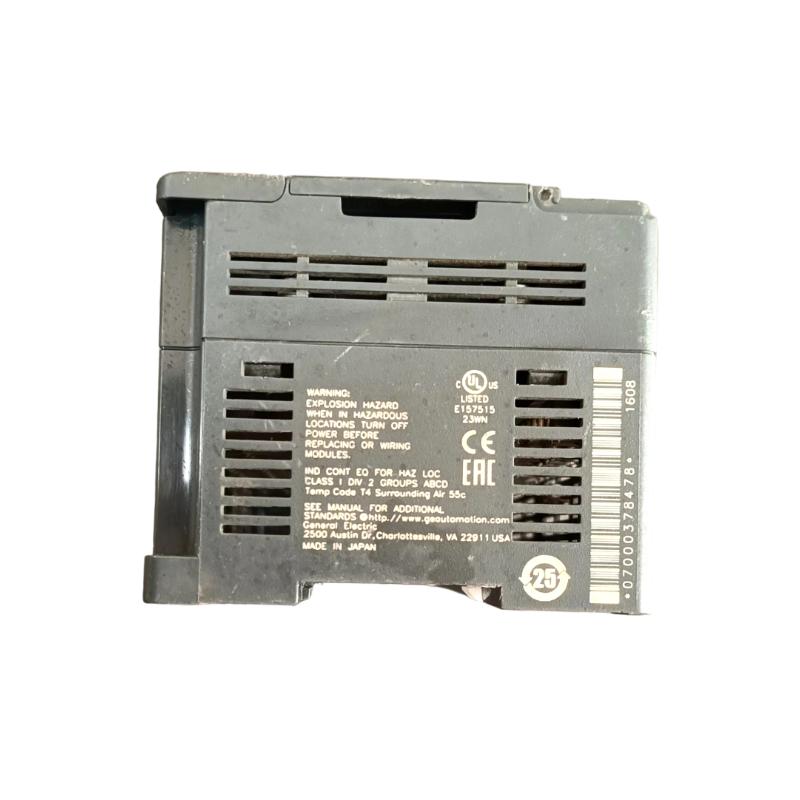
- GE
- IC200UDD064
- VersaMax Microcontroller Processor
- USA
- 150 x 90 x 76 mm
- 0.87 kg
- Xiamen, China
- New & In Stock
- T/T, PayPal, Western Union
- 1 Year
- 1-3 Working Days
- DHL, UPS, TNT, FedEx and EMS.
- 24-Hour Service
- COO
- 41
Our advantage

Global Logistics
We have a 10-year logistics and express cooperation agreement, so our products can be shipped to any place in the world.

Brand new and original
Our products are imported in bulk from the place of origin. Because of the cooperative relationship, our products are all original and 100% new.

24-hour service
We provide 7*24 hours service to our customers. We will be there whenever you need us.

Price advantage
All our products are priced very favorably because we have our own warehouse and supply.
| Company Information | |||
| [email protected] | |||
| Mobile | +8615980777398 | ||
| +8615980777398 | |||
| 15980777398 |
Product Overview
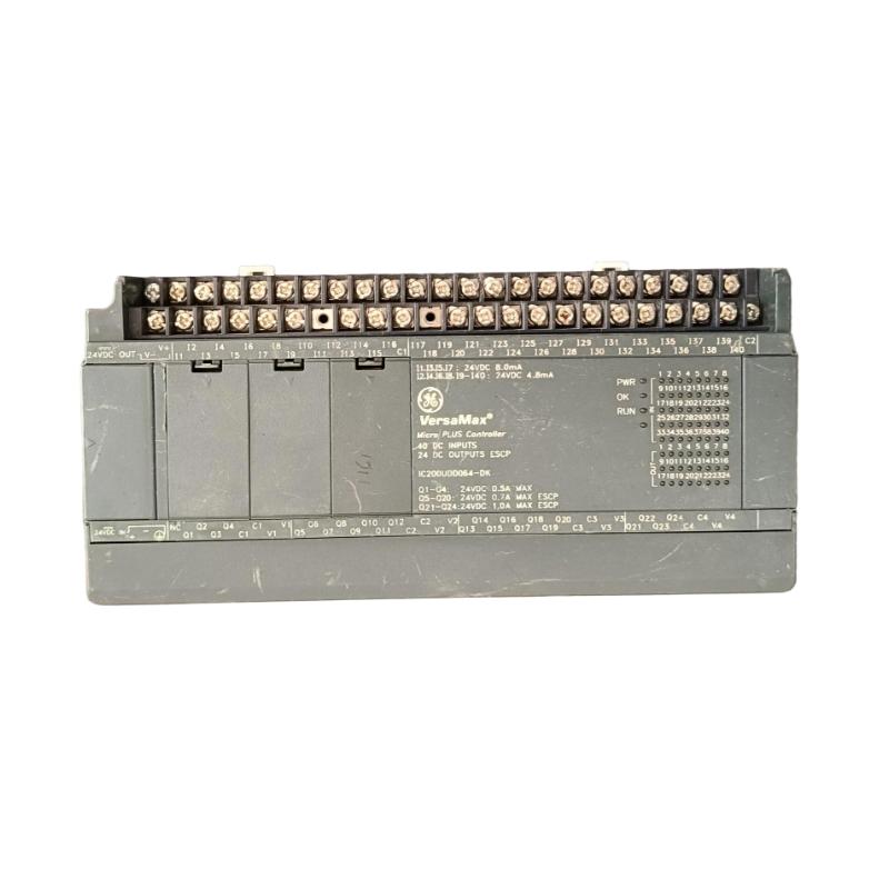
The GE IC200UDD064 VersaMax Microcontroller Processor is a compact industrial automation controller designed for compatible GE VersaMax control architectures. As a processor-level component, it performs the central processing functions required to execute control logic, manage I/O operations, coordinate sequences, process system data, and support communication with connected automation equipment.
In a typical industrial control system, field sensors provide input information to the controller, the processor evaluates this information according to the configured application, and output commands are then delivered to actuators and other field devices. The IC200UDD064 therefore occupies an important position between the field I/O layer and the overall machine or process-control strategy.
The supplied product information identifies the unit as a VersaMax Microcontroller Processor with dimensions of 150 × 90 × 76 mm and a weight of 0.87 kg.
Product Information
- Manufacturer: GE
- Product Family: VersaMax
- Model: IC200UDD064
- Product Type: Microcontroller Processor
- Dimensions: 150 × 90 × 76 mm
- Weight: 0.87 kg
- Primary Function: Programmable Control Processing
- Application: Industrial Automation
- System Role: Controller / Processor
The IC200UDD064 should be installed in a compatible VersaMax configuration with the appropriate power, I/O, communication, and application configuration.
Technical Specifications
| Parameter | Specification |
|---|---|
| Manufacturer | GE |
| Product Family | VersaMax |
| Model Number | IC200UDD064 |
| Product Type | Microcontroller Processor |
| Dimensions | 150 × 90 × 76 mm |
| Weight | 0.87 kg |
| Main Function | Control Processing |
| Application | Industrial Automation |
| System Role | Controller / Processor |
| Installation | Modular Automation System |
| Maintenance | Installation / Commissioning / Troubleshooting |
The dimensions and weight above are based on the product information supplied.
Function and Working Principle
The IC200UDD064 functions as the processing center of a compatible VersaMax automation system.
A simplified control architecture is:
Field Sensors
↓
Input Modules
↓
IC200UDD064 Processor
↓
User Application Logic
↓
Output Modules
↓
Actuators / Controlled Equipment
The processor continuously processes system information and executes the configured control application.
Typical control functions may include:
- Start and stop sequences
- Interlocking
- Timers
- Counters
- Logic operations
- Equipment sequencing
- Alarm handling
- Data processing
- Machine coordination
- Communication management
The processor combines information from the I/O system with the programmed control strategy to determine the required behavior of the connected equipment.
Role in VersaMax Automation Systems
The IC200UDD064 can serve as the central processing element in a modular automation system.
A typical structure can be represented as:
Sensors / Transmitters
↓
VersaMax Input Modules
↓
IC200UDD064
↓
Control Program
↓
VersaMax Output Modules
↓
Motors / Valves / Actuators
The processor can also participate in a larger control architecture:
Operator Station / Supervisory System
↕
Industrial Communication Network
↕
IC200UDD064
↕
VersaMax I/O
↕
Field Equipment
This architecture allows the controller to coordinate machine or process operation while exchanging information with other devices.
Controller Operating Principle
A programmable processor generally performs control operations in a repeated sequence.
Input Processing
The controller obtains current information from the connected input system.
Application Execution
The processor evaluates the user program using the available input and internal data.
Output Processing
The resulting control commands are transferred to the applicable output system.
Communication Processing
Applicable communication tasks are handled according to the system configuration.
Diagnostics
The controller monitors operating conditions and reports system-level faults or abnormal states where supported.
The cycle repeats continuously while the processor is operating normally.
Industrial Applications
Machine Automation
The IC200UDD064 can be used in programmable machine-control applications involving sensors, actuators, motors, and interlocking logic.
Typical equipment includes:
- Packaging machinery
- Assembly machines
- Conveyor systems
- Production equipment
- Material-handling machinery
Process Equipment
The processor can coordinate pumps, valves, motors, sensors, and other process equipment within a compatible automation architecture.
OEM Machinery
The compact controller architecture is suitable for machine builders requiring programmable control and I/O coordination.
Material Handling
The processor can manage sequences involving conveyors, sensors, motors, positioning equipment, and safety-related interlocks where supported by the overall control design.
Utility Equipment
Industrial utility systems can use programmable processors for equipment sequencing, monitoring, and automatic operation.
Installation Guide
1. Verify the Processor
Before installation, confirm:
GE IC200UDD064
VersaMax Microcontroller Processor
Inspect the unit for:
- Cracks
- Damaged housing
- Damaged connectors
- Damaged mounting surfaces
- Contamination
- Signs of mechanical impact
Confirm that the processor is the intended model for the control application.
2. Review the Existing Control System
Before installing or replacing the processor, document the existing configuration.
Record:
- Processor location
- I/O module arrangement
- Power supply configuration
- Communication connections
- Application program
- I/O assignments
- Controller settings
- Network parameters
This documentation can prevent configuration errors during commissioning.
3. Back Up the Application
If replacing an existing processor, preserve the applicable application and configuration before removing the original controller.
Where applicable, back up:
- User program
- Hardware configuration
- I/O configuration
- Communication parameters
- Controller settings
- Required retentive data
- Other application-specific parameters
A verified backup is especially important for production equipment.
4. Place the System in a Safe State
Because the processor can control machinery and process equipment, installation or replacement should be performed only after the controlled equipment has been placed in a safe condition.
Before maintenance:
- Identify affected equipment.
- Stop automatic operation.
- Place machinery in a safe state.
- Isolate hazardous energy where required.
- Follow the site’s maintenance and lockout procedures.
- Confirm that unexpected movement cannot occur.
5. Inspect the Mounting Area
Check the installation area for:
- Excessive dust
- Moisture
- Corrosion
- Excessive heat
- Mechanical vibration
- Damaged connectors
- Loose mounting hardware
The processor should be installed in a suitable industrial control environment.
6. Install the IC200UDD064
Position the processor correctly within the compatible VersaMax configuration.
Verify:
- Correct orientation
- Correct mounting location
- Proper mechanical engagement
- Connector alignment
- Secure installation
Do not force the processor into position.
7. Verify Power Connections
Before energizing the system, inspect the applicable control power arrangement.
Check:
- Power wiring
- Terminal connections
- Polarity where applicable
- Grounding
- Power distribution
- Supply stability
Incorrect power wiring can cause startup failures or equipment damage.
8. Verify I/O Connections
Inspect the connected I/O system.
Confirm:
- Correct module types
- Correct module positions
- I/O assignments
- Field wiring
- Terminal connections
- Sensor connections
- Actuator connections
A processor can operate correctly even when an I/O wiring problem causes the machine to malfunction.
9. Verify Communication Connections
If the controller communicates with external equipment, inspect:
- Network cables
- Connectors
- Device addressing
- Communication parameters
- Network topology
- Connected devices
Communication problems should be isolated from processor execution problems during troubleshooting.
Commissioning Procedure
Step 1 — Visual Inspection
Inspect the IC200UDD064 and the complete controller assembly.
Step 2 — Verify Power
Confirm that the processor receives stable control power.
Step 3 — Verify Hardware Configuration
Confirm that the physical I/O arrangement matches the intended configuration.
Step 4 — Restore the Application
Load or restore the correct application program and configuration.
Step 5 — Check Processor Status
Review available processor status and diagnostic information.
Step 6 — Test Inputs
Verify that expected field inputs are detected correctly.
Step 7 — Test Outputs
Test outputs under controlled and safe conditions.
Step 8 — Test Communication
Verify communication with connected automation equipment.
Step 9 — Test Control Sequences
Run the application through controlled operating sequences.
Step 10 — Return to Service
After successful testing, return the equipment to normal automatic operation.
Troubleshooting Guide
Problem 1: Processor Does Not Start
Possible causes include:
- Missing control power
- Incorrect power wiring
- Loose connection
- Processor installation problem
- Hardware fault
- Configuration problem
Diagnostic Procedure
- Verify control power.
- Inspect power wiring.
- Check processor installation.
- Review status indications.
- Check diagnostic information.
- Inspect connected modules.
Power should always be checked before assuming that the processor has failed.
Problem 2: Processor Starts but Application Does Not Run
Possible causes include:
- Incorrect operating state
- Application configuration problem
- Program problem
- I/O configuration mismatch
- Startup condition not satisfied
- System diagnostic fault
Review processor status and diagnostic information before changing the application.
Problem 3: Processor Repeatedly Resets
Potential causes include:
- Unstable control power
- Loose power connections
- Electrical interference
- Hardware problem
- Environmental stress
- System-level fault
Recommended Diagnostic Sequence
Power Supply
↓
IC200UDD064
↓
I/O System
↓
Communication Network
↓
Environmental Conditions
Monitor the control power while reviewing processor diagnostics.
Problem 4: Inputs Are Not Updating
Possible causes:
- Failed sensor
- Broken field wiring
- Input module fault
- Incorrect I/O configuration
- Module connection problem
- Processor communication problem
Determine whether the failure affects one input, one module, or the complete I/O system.
Problem 5: Outputs Do Not Operate
Possible causes include:
- Incorrect application logic
- Output module problem
- Field wiring fault
- Missing output power
- Interlock condition
- Processor operating-state problem
Verify the internal output command and the physical output circuit separately.
Problem 6: Communication Is Lost
Possible causes include:
- Damaged network cable
- Loose connector
- Incorrect device address
- Incorrect communication parameters
- Network equipment failure
- Processor configuration problem
Start with physical network connections before modifying software configuration.
Problem 7: Machine Operates Incorrectly
If the processor appears healthy but the machine does not operate as expected, investigate:
- I/O mapping
- Application logic
- Sensor signals
- Actuator wiring
- Interlocks
- Parameters
- Communication data
The root cause may be located outside the processor.
Problem 8: I/O Configuration Fault
If the controller reports an I/O configuration problem, verify:
- Module positions
- Module types
- Module order
- I/O assignments
- Hardware configuration
The actual physical configuration must correspond to the intended controller configuration.
Problem 9: Controller Becomes Unstable After Maintenance
Possible causes include:
- Loose connectors
- Disturbed power wiring
- Incorrect configuration
- Damaged communication cable
- Poor module seating
- Environmental disturbance
Review all equipment and connections that were touched during maintenance.
Problem 10: Processor Replacement Does Not Solve the Fault
If the same problem remains after installing another IC200UDD064, investigate:
- Power supply
- I/O modules
- Field wiring
- Sensors
- Actuators
- Communication equipment
- Application program
- Hardware configuration
This prevents repeated replacement of healthy processor hardware.
Diagnostic Strategy
A systematic troubleshooting path is:
Power Supply
↓
IC200UDD064 Processor
↓
I/O Modules
↓
Field Wiring
↓
Sensors / Actuators
For communication faults:
IC200UDD064
↓
Network Interface
↓
Communication Network
↓
External Equipment
This approach helps separate processor problems from I/O, field, and network problems.
Processor Replacement Procedure
Phase 1 — Preparation
- Confirm GE IC200UDD064.
- Verify the replacement processor.
- Back up the existing application.
- Record the hardware configuration.
- Record communication settings.
- Identify affected equipment.
- Place the system in a safe condition.
Phase 2 — Removal
- Follow the approved shutdown procedure.
- Remove power as required.
- Identify connected cables.
- Disconnect applicable interfaces.
- Remove the existing processor carefully.
- Inspect the mounting interface.
Phase 3 — Installation
- Inspect the replacement processor.
- Align it correctly.
- Install the IC200UDD064.
- Confirm secure mechanical engagement.
- Reconnect applicable interfaces.
- Verify power connections.
Phase 4 — Configuration
- Restore the correct application.
- Verify hardware configuration.
- Confirm I/O assignments.
- Verify communication parameters.
- Review processor diagnostics.
Phase 5 — Commissioning
- Apply control power.
- Confirm processor startup.
- Check diagnostics.
- Test inputs.
- Test outputs.
- Verify communications.
- Test control sequences.
- Return the system to normal operation.
Preventive Maintenance
| Maintenance Item | Recommended Action |
|---|---|
| IC200UDD064 | Inspect physical condition |
| Power Supply | Check stability |
| Connectors | Inspect engagement |
| I/O Modules | Check condition |
| Communication Network | Inspect connections |
| Application Program | Maintain verified backup |
| Hardware Configuration | Document changes |
| Cabinet | Check cleanliness and environment |
| Grounding | Verify system arrangement |
| Diagnostics | Review recurring faults |
| Field Wiring | Inspect terminals |
| Maintenance Records | Document service activities |
Environmental Considerations
Temperature
Excessive cabinet temperature can reduce electronic component reliability and contribute to controller instability.
Dust
Dust accumulation can affect connectors and overall cabinet cleanliness.
Moisture
Moisture or condensation may cause corrosion, leakage, or other electrical problems.
Vibration
Continuous mechanical vibration can affect connectors, mounting structures, and field wiring.
Electrical Noise
Motors, contactors, variable-frequency drives, and switching equipment can generate electrical interference.
Proper cabinet design, grounding, and cable separation can reduce these risks.
Common Installation Mistakes
Installing the Wrong Processor
Always verify the complete IC200UDD064 model number before installation.
Failing to Back Up the Application
A processor replacement without an appropriate application backup can significantly increase commissioning time.
Incorrect I/O Configuration
The physical module arrangement must correspond to the intended configuration.
Incorrect Communication Settings
Incorrect network parameters can prevent communication even when the processor itself is operating normally.
Loose Connections
Poorly seated power, I/O, or communication connections can cause intermittent faults.
Ignoring Power Quality
Repeated resets or unstable operation can originate from the control power supply rather than the processor.
Key Advantages
- VersaMax microcontroller processor architecture
- Centralized programmable control
- Suitable for industrial automation applications
- Supports coordinated I/O processing
- Suitable for machine and process sequencing
- Provides centralized control-processing functions
- Compatible with modular automation architectures
- Supplied dimensions of 150 × 90 × 76 mm
- Supplied weight of 0.87 kg
- Suitable for OEM and industrial control applications
Technical FAQs
What is the GE IC200UDD064?
The GE IC200UDD064 is a VersaMax Microcontroller Processor used as the central processing component of a compatible industrial automation system.
What is the primary function of IC200UDD064?
Its primary function is to execute the control application and coordinate I/O processing, machine logic, diagnostics, and applicable communication functions.
What are the dimensions of IC200UDD064?
The supplied dimensions are 150 × 90 × 76 mm.
What is the weight of IC200UDD064?
The supplied weight is 0.87 kg.
What can cause the processor not to start?
Possible causes include missing or unstable power, incorrect wiring, poor module installation, hardware faults, or configuration problems.
Why does a processor repeatedly reset?
Investigate control power, loose connections, electrical interference, hardware conditions, environmental conditions, and connected system faults.
Why are inputs not detected?
Check the field sensor, wiring, I/O module, module connections, I/O configuration, and processor status.
Why are outputs not activating?
Check the application logic, interlocks, output module, field wiring, output power, and processor operating state.
Can a communication fault indicate a processor failure?
Not necessarily. Network cabling, connectors, addressing, configuration, communication equipment, and external devices should be checked first.
What should be backed up before replacing the processor?
Preserve the applicable control application, hardware configuration, I/O assignments, communication settings, parameters, and required controller data.
Why is I/O configuration important?
The controller must correctly associate the physical I/O hardware with the application configuration. A mismatch can produce configuration faults or incorrect machine behavior.
Should the IC200UDD064 be replaced whenever a machine stops?
No. Power, processor status, I/O, communication, field wiring, sensors, actuators, and application logic should be checked systematically before replacing the controller.
Conclusion
The GE IC200UDD064 VersaMax Microcontroller Processor is a central processing component for compatible VersaMax industrial automation systems. Based on the supplied information, the unit measures 150 × 90 × 76 mm and weighs 0.87 kg.
Its role is to execute the programmed control strategy and coordinate information between the I/O system, field equipment, communication infrastructure, and higher-level control functions. Reliable operation therefore depends on the complete automation system rather than the processor alone.
During installation, technicians should verify the exact model, preserve the existing application and configuration, place controlled equipment into a safe condition, inspect the installation area, and ensure correct power, I/O, and communication connections. Commissioning should proceed systematically through processor startup, I/O testing, communication verification, and controlled machine operation.
When troubleshooting, power supply, I/O hardware, field wiring, communication infrastructure, application logic, and configuration should all be considered. A structured diagnostic process can prevent unnecessary replacement of healthy processor hardware.
With appropriate installation, configuration management, environmental control, and preventive maintenance, the IC200UDD064 can provide dependable processing and control functionality within a compatible GE VersaMax automation architecture.