

ProductPRODUCT
Featured products
Contact Us
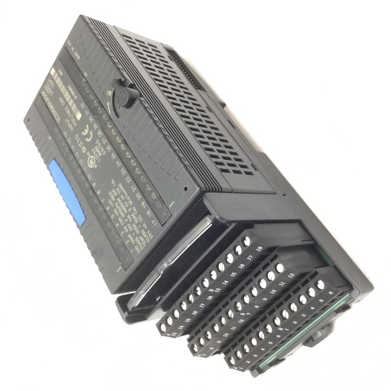
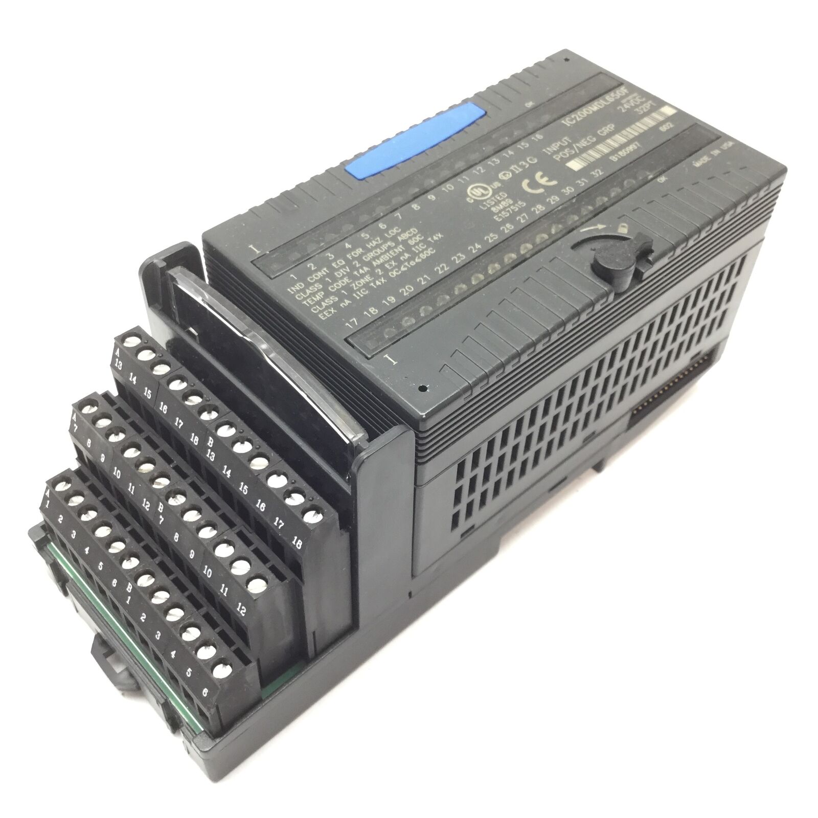
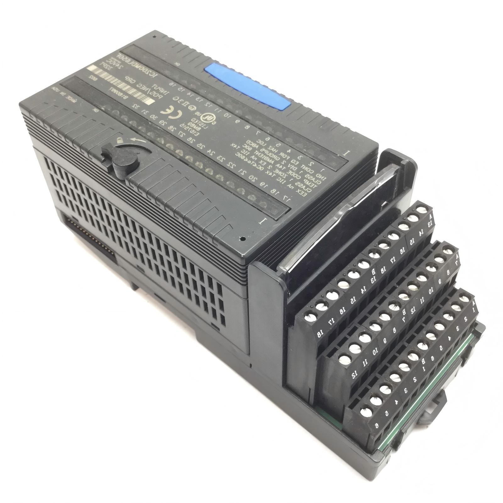
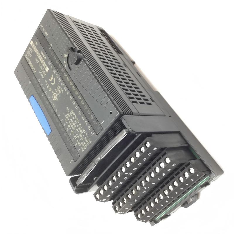
- GE
- IC200MDL650F
- VersaMax Discrete Input Module
- USA
- 110 x 66.8 x 50 mm
- 0.3 kg
- Xiamen, China
- New & In Stock
- T/T, PayPal, Western Union
- 1 Year
- 1-3 Working Days
- DHL, UPS, TNT, FedEx and EMS.
- 24-Hour Service
- COO
- 3
Our advantage

Global Logistics
We have a 10-year logistics and express cooperation agreement, so our products can be shipped to any place in the world.

Brand new and original
Our products are imported in bulk from the place of origin. Because of the cooperative relationship, our products are all original and 100% new.

24-hour service
We provide 7*24 hours service to our customers. We will be there whenever you need us.

Price advantage
All our products are priced very favorably because we have our own warehouse and supply.
| Company Information | |||
| [email protected] | |||
| Mobile | +8615980777398 | ||
| +8615980777398 | |||
| 15980777398 |
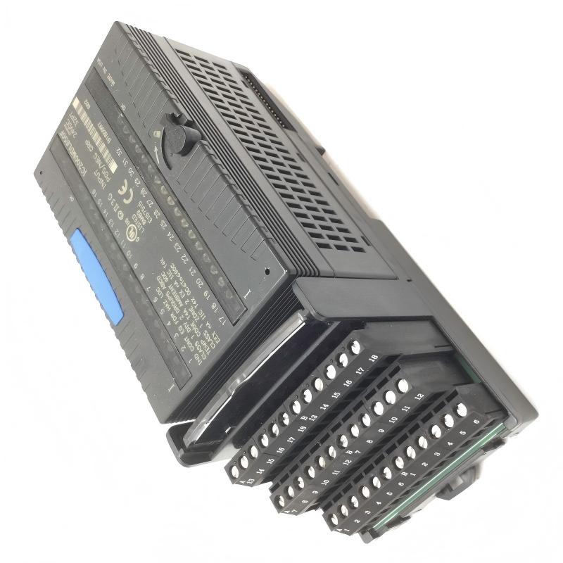
1. Product Overview
The GE IC200MDL650F VersaMax Discrete Input Module is an industrial automation component designed for use in compatible GE Fanuc VersaMax control systems. Discrete input modules enable a programmable logic controller (PLC) to monitor the on/off status of field devices, allowing the controller to respond to machine conditions, operator commands, and equipment interlocks.
In industrial applications, discrete input signals commonly originate from push buttons, selector switches, limit switches, proximity sensors, relay contacts, and other devices that provide two-state information. The input module interfaces these field signals with the PLC system, helping translate external device conditions into information that the controller can use in its logic program.
The IC200MDL650F model belongs to the VersaMax product family. Before installation or replacement, users should verify the exact electrical characteristics, input channel configuration, wiring requirements, and hardware compatibility for this specific model and revision. These details should not be inferred solely from the product family name.
With listed dimensions of 110 × 66.8 × 50 mm and a weight of 0.3 kg, the module is suitable for consideration in industrial control cabinet layouts where its mechanical footprint, mounting arrangement, and electrical specifications match the existing system.
For maintenance engineers, system integrators, and industrial spare-parts buyers, confirming the complete part number is essential to ensure that the replacement module matches the original equipment configuration.
2. Technical Specifications
| Parameter | Specification |
|---|---|
| Brand | GE Fanuc |
| Model Number | IC200MDL650F |
| Product Family | VersaMax |
| Product Name | Discrete Input Module |
| Product Category | PLC Digital Input Module |
| Dimensions | 110 × 66.8 × 50 mm |
| Weight | 0.3 kg |
| Primary Function | Acquisition of discrete field input signals |
| Signal Type | Discrete on/off signals; exact electrical type requires verification |
| Input Channel Count | Verify from the exact model documentation |
| Rated Input Voltage | Verify from the exact model documentation |
| Input Current | Verify from the exact model documentation |
| Input Response Time | Verify from the exact model documentation |
| Isolation Characteristics | Verify from the exact model documentation |
| Mounting and Base Requirements | Confirm the compatible VersaMax carrier or installation arrangement |
| Application | Industrial machine control and automation |
| Replacement Requirement | Match the complete model number and confirm system compatibility |
The dimensions and weight above are the supplied product specifications. Channel count, input voltage, polarity, wiring arrangement, isolation, and response time should be confirmed before connecting field devices.
3. Function and Working Principle
3.1 Acquisition of Discrete Signals
A discrete input module allows a PLC to monitor field devices that operate in defined states, such as ON and OFF. For example, a limit switch may indicate that a machine component has reached a specific position, while a push button may signal an operator request.
The input module receives the electrical signal from the field device and makes the corresponding input state available to the PLC system. The controller then evaluates that state according to the application program.
The exact electrical conditions interpreted as ON or OFF depend on the module’s input specifications and the wiring configuration.
3.2 Signal Conditioning
Industrial field signals may be affected by electrical noise, switching transients, and contact behavior. Discrete input circuits typically incorporate electrical conditioning appropriate to their design to help the module interpret field signals reliably.
The specific filtering, threshold, and transient-handling characteristics of the IC200MDL650F should be verified from its technical documentation. Engineers should not assume that every discrete input module uses the same input voltage range or filtering behavior.
3.3 Communication with the PLC System
In a compatible VersaMax installation, input states are transferred through the supported hardware architecture to the controller. The PLC program can then use the input information to control outputs, trigger sequences, activate alarms, or manage interlocks.
The module itself does not determine the full machine-control sequence. Its role is to provide input information to the controller, while the control logic and system configuration determine how the information is used.
3.4 Support for Equipment Monitoring
Discrete inputs are widely used to monitor machine status and operating conditions. Depending on the connected field devices, input information may indicate whether a guard is closed, a motor auxiliary contact is active, a valve position switch has changed state, or a material sensor has detected an object.
Applications involving safety functions require particular care. A standard PLC input module must not be assumed to provide a certified safety function unless the complete system has been specifically designed and validated for that purpose.
4. Role in Industrial Control Systems
4.1 Interface Between Field Devices and PLC Logic
The IC200MDL650F provides a discrete-input interface between compatible field wiring and the PLC control system. Without the appropriate input interface, the controller may not be able to acquire the electrical status of external devices in the required manner.
Correct selection is important because the input module must match the electrical characteristics of the connected devices and the supported control-system architecture.
4.2 Machine Sequence Control
Automated machines often rely on a series of discrete conditions before moving to the next step of a production sequence. These conditions may include the presence of a workpiece, confirmation of a cylinder position, activation of a limit switch, or receipt of an operator command.
The input module supplies the relevant status information to the PLC, enabling the programmed sequence to proceed when its conditions are satisfied.
4.3 Equipment Interlocking
Industrial control logic frequently uses discrete signals to prevent incompatible operations. For example, a controller may require a door-position signal, a pressure-switch state, or a motor-ready contact before allowing a process step to begin.
The input module can participate in this monitoring arrangement, but the quality of the interlock depends on the entire system, including field devices, wiring, PLC logic, and output equipment.
4.4 Fault Monitoring and Diagnostics
Unexpected input states can help maintenance personnel identify problems such as broken conductors, failed switches, incorrect wiring, or disconnected sensors. Depending on the field circuit design, a failed device may appear as a permanently ON or OFF input.
Because different faults can produce similar symptoms, technicians should compare the physical field condition, electrical measurements, module status, and PLC logic rather than relying on a single indication.
5. Industrial Applications
5.1 Manufacturing and Assembly Lines
Assembly systems use discrete signals to detect workpieces, confirm fixture positions, monitor machine doors, and track the completion of individual process steps.
A compatible VersaMax input module can provide the PLC with the required status information when the connected field devices and electrical characteristics match the module specifications.
5.2 Conveyor and Material Handling Systems
Conveyor systems use photoelectric sensors, proximity switches, limit switches, and motor-status contacts to monitor material movement and equipment conditions.
The PLC uses these signals to coordinate conveyor sections, identify product positions, and manage sequence transitions. Reliable operation depends on correct input wiring, appropriate sensor selection, and suitable controller logic.
5.3 Packaging Machinery
Packaging equipment may monitor container presence, product position, guard status, actuator feedback, and cycle-completion signals. Discrete input data allows the controller to coordinate machine movements and detect missing process conditions.
The IC200MDL650F may be considered for compatible installations where its exact input characteristics meet the requirements of the connected devices.
5.4 Process and Utility Equipment
Pumps, compressors, water-treatment equipment, and auxiliary process systems often use discrete contacts to indicate running status, pressure-switch activation, valve position, and equipment availability.
Input signals can support sequencing, alarm generation, and equipment monitoring. Any process-critical application should be evaluated against the required reliability and safety standards.
5.5 Building and Facility Automation
Some facility systems use discrete inputs to monitor equipment contacts, door switches, local operating commands, and status relays. Integration requires confirmation that the field voltage, input type, and grounding arrangement are compatible with the module.
6. Installation and System Integration
6.1 Verify the Complete Model Number
Before installation, confirm that the module label reads IC200MDL650F. Check the complete part number, hardware revision, and existing system records.
Modules within the same product family may differ in voltage range, channel arrangement, electrical characteristics, or mounting requirements. Similar appearance does not establish electrical interchangeability.
6.2 Confirm Electrical Compatibility
Before connecting field devices, verify:
- Rated input voltage and acceptable operating range.
- Input channel count and terminal assignments.
- Supported field-device wiring arrangements.
- Input polarity and common-terminal requirements.
- Input current and response characteristics.
- Isolation and grounding requirements.
- Compatibility with the installed VersaMax hardware configuration.
Do not apply field voltage until these details have been confirmed. Incorrect voltage or wiring may damage the module or connected equipment.
6.3 Inspect the Module and Mounting Hardware
Inspect the module for physical damage, contamination, bent contacts, damaged terminal interfaces, and signs of overheating. Confirm that the intended carrier, base, or mounting arrangement is compatible with the specific module.
Do not force the module into place or modify the connector, carrier, or housing to achieve a fit.
6.4 Follow Electrical Safety Procedures
Before installing or removing the module, follow the equipment manufacturer’s instructions and site safety procedures. Isolate power where required, verify the safe state of connected circuits, and apply lockout/tagout procedures when appropriate.
Field wiring may remain energized independently of the PLC rack. Confirm that all relevant sources of electrical energy have been addressed before touching terminals or conductors.
6.5 Connect Field Devices
Connect each field device according to the verified wiring diagram for the exact module. Label conductors and terminal assignments clearly to simplify future maintenance.
Keep field wiring organized and follow applicable requirements for grounding, shielding, cable routing, and separation from high-noise power conductors. The appropriate wiring method depends on the signal type and installation environment.
6.6 Configure the PLC Hardware
Confirm that the module is represented correctly in the controller’s hardware configuration, where required by the installed system. Verify the input addresses, channel assignments, and logic references before returning the machine to service.
Do not assume that an existing configuration will remain correct after a module replacement or rack modification.
6.7 Test Input Operation
After completing installation and the required safety checks, test each connected input using an approved commissioning procedure.
A typical test includes:
- Confirming the correct module identification and installation.
- Checking field wiring against the approved diagram.
- Operating the field device under controlled conditions.
- Verifying that the corresponding input state changes as expected.
- Confirming that the PLC logic responds correctly.
- Recording any discrepancies before releasing the equipment.
Testing should be performed by qualified personnel using procedures suitable for the machine and process.
7. Troubleshooting Common Problems
7.1 Input Signal Does Not Change
Possible causes:
- Incorrect field wiring.
- Missing or incorrect field supply voltage.
- Faulty sensor or switch.
- Incorrect terminal assignment.
- Incompatible input signal type.
- Incorrect PLC address or program reference.
Recommended checks:
Verify the field-device supply, inspect wiring against the exact module diagram, and test the field device independently where safe. Compare the physical device state with the input indication and the PLC program’s referenced address.
7.2 Input Remains Permanently ON
Possible causes:
- A field contact is stuck closed.
- A conductor is shorted to the active supply.
- The sensor is continuously detecting a target.
- The wiring polarity or common connection is incorrect.
- The PLC program is reading a different address than expected.
Recommended checks:
Inspect the field device and wiring, then verify the electrical state at the module terminals using appropriate instruments and safe procedures. Confirm the input address in the controller configuration before concluding that the module has failed.
7.3 Input Remains Permanently OFF
Possible causes:
- An open conductor.
- A disconnected field-device supply.
- A failed sensor or switch.
- Incorrect wiring or polarity.
- An input signal below the required operating threshold.
Recommended checks:
Check the field supply and wiring continuity under safe conditions. Confirm that the field device produces the correct signal for the module’s specified input type and voltage range.
7.4 Intermittent Input Signals
Possible causes:
- Loose terminals.
- Damaged cables.
- Electrical interference.
- Unstable field-device power.
- Mechanical vibration affecting a switch or connection.
- A signal-filtering or response-time mismatch.
Recommended checks:
Inspect terminals and cable routing, monitor the field signal during the fault, and compare the actual signal behavior with the module’s documented electrical characteristics. Do not change filtering or controller logic without understanding the process implications.
7.5 PLC Hardware Configuration Problems
Possible causes:
- Incorrect module identification.
- Incorrect rack or carrier configuration.
- Incorrect I/O address mapping.
- A connector or mounting issue.
- Hardware incompatibility.
Recommended checks:
Review the system’s hardware configuration, verify the module and mounting arrangement, and inspect the relevant controller diagnostics. Confirm compatibility before replacing the module.
7.6 Suspected Module Failure
Before declaring the IC200MDL650F defective, rule out field-device faults, wiring problems, incorrect supply voltage, configuration errors, and connector issues.
If the fault remains, follow the manufacturer’s diagnostic and replacement procedures. Use a replacement that has been confirmed compatible with the installed hardware and application.
8. Compatible System Components
The following table identifies component categories commonly associated with discrete-input integration. It does not establish specific part-number compatibility with the IC200MDL650F.
| Component Category | Role in the System | Verification Required |
|---|---|---|
| Compatible VersaMax Controller | Executes the application logic | Confirm controller and system compatibility |
| Compatible Module Carrier or Base | Provides the required physical and electrical interface | Verify the exact supported hardware |
| Field Sensors | Detect position, presence, or process conditions | Match signal type and electrical ratings |
| Limit and Selector Switches | Provide discrete operating states | Verify contact configuration and input requirements |
| Relay Auxiliary Contacts | Report equipment status | Confirm contact ratings and wiring arrangement |
| Field Power Supply | Supplies compatible field circuits | Confirm voltage, current capacity, and grounding |
| Terminal Blocks | Organize field wiring | Check terminal ratings and wiring standards |
| Industrial Control Cabinet | Houses and protects the control equipment | Verify environmental conditions and clearances |
9. Recommended Alternative Models
Selecting a substitute for the GE IC200MDL650F requires more than matching the VersaMax family name. Input modules may differ in channel count, voltage rating, input type, terminal layout, isolation, and supported hardware revision.
| Replacement Option | Recommendation |
|---|---|
| Exact GE IC200MDL650F | Preferred when it matches the original hardware requirement and condition |
| Manufacturer-approved revision | Consider only after confirming documented compatibility |
| Another VersaMax discrete input module | Verify all electrical, mechanical, and configuration differences before substitution |
| Input module from another PLC family | Do not treat as a direct replacement without a complete system redesign and compatibility review |
No specific alternative model is presented as a confirmed drop-in replacement. Check the complete model number, module documentation, and installed system configuration before purchasing a substitute.
10. Key Advantages
Reliable Field Signal Acquisition
When installed and wired according to its specifications, a compatible discrete input module allows a PLC to acquire the ON/OFF states of industrial field devices.
Integration with Automated Control Logic
Input information enables a controller to coordinate machine sequences, monitor equipment status, and respond to external conditions.
Broad Potential Application Range
Discrete input interfaces are used in manufacturing, packaging, material handling, utilities, and process equipment. Suitability for a particular application depends on the exact module characteristics.
Maintainable System Architecture
Clearly identified input channels and organized field wiring make commissioning, troubleshooting, and future system maintenance more manageable.
Practical Spare-Parts Identification
Recording the full IC200MDL650F model number, dimensions, weight, and associated equipment helps maintenance teams manage inventory and reduce selection errors.
11. Technical FAQs
Q1: What is the GE IC200MDL650F?
The GE IC200MDL650F is identified as a VersaMax discrete input module used in compatible industrial automation systems to interface discrete field signals with PLC control logic.
Q2: What are the dimensions and weight of the IC200MDL650F?
The supplied dimensions are 110 × 66.8 × 50 mm, and the supplied weight is 0.3 kg.
Q3: What devices can connect to a discrete input module?
Depending on the module’s electrical specifications, discrete inputs may be connected to devices such as switches, proximity sensors, photoelectric sensors, push buttons, and relay contacts. Confirm the exact input voltage, polarity, and wiring requirements before connecting any device.
Q4: How many input channels does the IC200MDL650F have?
The channel count should be confirmed from the technical documentation for the exact IC200MDL650F revision. Do not infer it from dimensions or from another module in the same product family.
Q5: What input voltage does this module support?
The exact rated input voltage and operating range must be verified from the module’s specifications. Applying an unverified voltage can cause equipment damage or unreliable operation.
Q6: Can the IC200MDL650F replace another VersaMax input module?
Not automatically. Verify the input type, voltage range, channel count, terminal assignment, carrier compatibility, and PLC configuration before substitution.
Q7: Why does a connected sensor fail to register in the PLC?
Common causes include incorrect wiring, missing field power, an incompatible signal, a faulty sensor, incorrect I/O addressing, or a configuration problem. Troubleshooting should begin with the field device and wiring before the module is replaced.
Q8: Does replacing the module require PLC configuration changes?
It depends on the installed system and whether the replacement has identical supported characteristics. Review the hardware configuration, input addresses, and application logic as part of the replacement procedure.
Q9: What should be checked before ordering a replacement?
Confirm the complete model number and revision, dimensions, input specifications, terminal arrangement, carrier compatibility, and the configuration of the existing PLC system. A clear photograph of the label and mounting interface can help with identification.
Q10: Can this module be used in a safety-critical application?
Do not assume that a standard discrete input module provides a certified safety function. Safety-related applications require appropriate certified components and a validated system architecture designed for the relevant safety requirements.
12. Conclusion
The GE IC200MDL650F VersaMax Discrete Input Module provides a discrete-signal interface for compatible industrial automation systems. Its role is to allow the PLC to monitor external device states and use that information in programmed machine sequences, equipment monitoring, and process control.
The supplied product dimensions are 110 × 66.8 × 50 mm, with a weight of 0.3 kg. Before installation or replacement, confirm the exact electrical ratings, input channel configuration, wiring requirements, mounting hardware, and controller compatibility.
For industrial maintenance teams, system integrators, and spare-parts purchasers, accurate model identification and careful commissioning are essential to achieving dependable input monitoring and minimizing avoidable downtime.