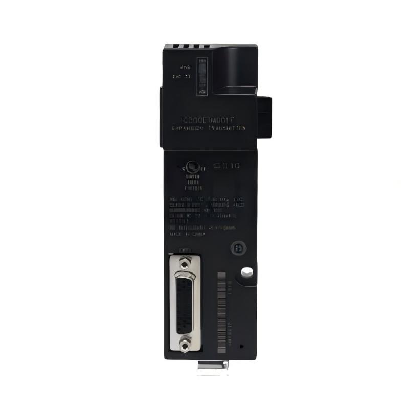
Product Overview
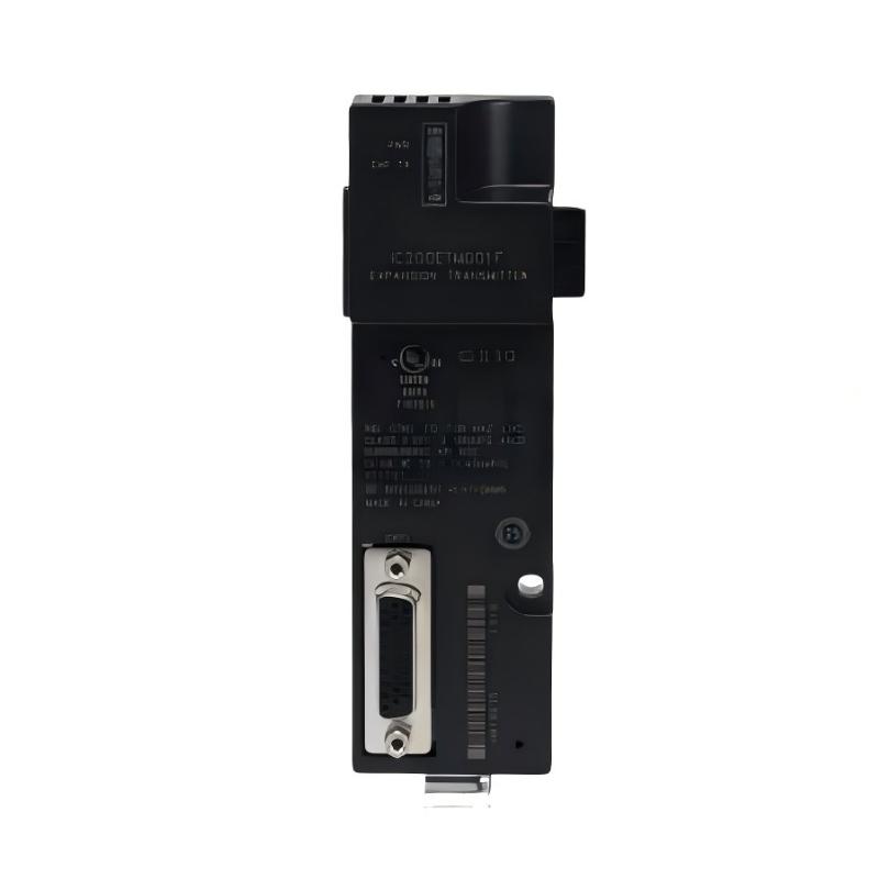
The GE IC200ETM001 VersaMax Extended Transmitter Module is an expansion communication component used in GE VersaMax modular automation systems. Its primary role is to transmit system information from the main VersaMax control section toward an extended I/O section, supporting the connection of additional I/O hardware within a larger control architecture.
In industrial automation, a PLC system may need to control a large number of field devices distributed across different machine sections. When all I/O modules are installed in one location, field wiring can become complicated and control-panel space may become difficult to manage. An extended I/O architecture provides a way to separate sections of the system while maintaining coordinated operation.
The IC200ETM001 works as part of this extended architecture. It is not a CPU module, digital input module, digital output module or power supply. Instead, it performs a system-level communication function associated with transmitting information toward an extended VersaMax I/O section.
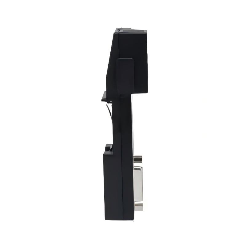
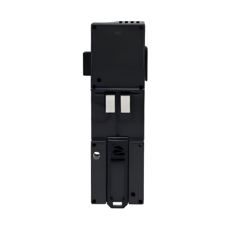
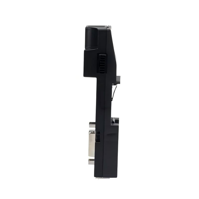
The specified dimensions of the IC200ETM001 are 150 × 35 × 100 mm, with a weight of approximately 0.14 kg. Its elongated compact form factor allows it to be integrated into an industrial control cabinet where additional I/O expansion is required.
The transmitter and receiver functions should be considered together. In an extended system, the transmitter is associated with the originating or main side of the expansion path, while the receiver is associated with the extended I/O side.
Technical Specifications
| Parameter |
Details |
| Manufacturer |
GE / GE Fanuc |
| Product Series |
VersaMax |
| Model |
IC200ETM001 |
| Product Type |
Extended Transmitter Module |
| Main Function |
Extended I/O system transmission |
| Application |
VersaMax modular and distributed I/O systems |
| Dimensions |
150 × 35 × 100 mm |
| Weight |
0.14 kg |
| Installation |
VersaMax modular control system |
| System Architecture |
Extended I/O |
| Communication Role |
Transmits system information toward an extended I/O section |
| I/O Function |
Supports extended I/O architecture |
| Controller Relationship |
Interfaces with the main VersaMax system |
| Application Type |
Machine and process automation |
| Maintenance |
Modular transmitter replacement |
| Environment |
Industrial control cabinet |
| Mounting |
System-dependent VersaMax installation |
Function and Working Principle
The main function of the IC200ETM001 is to provide the transmission side of an extended VersaMax I/O architecture.
A simplified system structure can be represented as:
VersaMax CPU / Main I/O → IC200ETM001 → Expansion Connection → Extended I/O Section
The transmitter sends the required system information from the primary section toward the extended section.
This architecture allows the main VersaMax control system to communicate with additional I/O hardware located outside the primary I/O section.
Transmission of Control Information
For output-related operations, information can follow a path such as:
PLC CPU → IC200ETM001 → Extended I/O Architecture → Output Module → Actuator
This allows output commands generated by the PLC application to reach devices installed within the extended I/O section.
Return of Input Information
Input information follows the opposite direction through the extended architecture:
Field Device → Input Module → Extended I/O Architecture → Main VersaMax System → CPU
The transmitter therefore forms one part of the overall communication path that allows the main control system and extended I/O section to operate together.
Role in Industrial Control Systems
The IC200ETM001 plays a system-expansion role rather than a conventional field-signal processing role.
A typical extended architecture can contain:
VersaMax CPU
↓
Main I/O Section
↓
IC200ETM001 Extended Transmitter
↓
Expansion Connection
↓
Extended Receiver
↓
Additional I/O Modules
↓
Field Devices
The CPU remains responsible for executing the PLC program. The transmitter and receiver architecture supports the communication required between the primary and extended portions of the I/O system.
This arrangement is useful when I/O hardware must be physically separated from the main control cabinet or when the number of required I/O modules makes a single local arrangement impractical.
Industrial Applications
The GE IC200ETM001 can be used in VersaMax automation systems that require extended I/O architecture.
Typical applications include:
- Factory automation
- Production lines
- Packaging machinery
- Conveyor systems
- Material handling
- Assembly equipment
- Manufacturing machinery
- Machine-control systems
- Process automation
- Distributed I/O applications
- Large industrial machines
- OEM automation equipment
- Multi-section control cabinets
- Automated production systems
For large machines, extended I/O can help place I/O modules closer to sensors and actuators, reducing the amount of field wiring that needs to return to the central control cabinet.
Extended Transmitter and Receiver Architecture
The relationship between the transmitter and receiver is important when designing or troubleshooting an extended VersaMax system.
A simplified architecture is:
Main System
CPU → Transmitter → Expansion Link
↓
Extended Section
Receiver → I/O Modules
The transmitter is associated with the originating side of the expansion path, while the receiver is associated with the destination or extended I/O side.
This arrangement allows the two portions of the system to function as a coordinated control architecture.
Why Extended I/O Is Useful
An extended I/O architecture can provide several practical benefits:
- Flexible I/O placement
- Better cabinet organization
- Reduced field-wiring distance
- Easier machine-section separation
- Improved accessibility
- More scalable system design
- Simplified expansion of I/O capacity
For example, a long conveyor may have sensors and actuators distributed along its entire length. Placing all I/O modules beside the CPU could require long individual field cables. Extended I/O can provide a more organized alternative.
Extended Transmitter vs. Extended Receiver
The IC200ETM001 should not be confused with the IC200ERM001 or IC200ERM002.
| Feature |
IC200ETM001 |
IC200ERM001 / IC200ERM002 |
| Product Type |
Extended Transmitter Module |
Extended Receiver Module |
| Main Role |
Transmits information toward extended section |
Receives information at extended section |
| System Position |
Main/originating side |
Extended I/O side |
| I/O Expansion |
Supports expansion architecture |
Supports expansion architecture |
| CPU Function |
No |
No |
| Field I/O Processing |
No |
No |
| System Relationship |
Works with extended receiver architecture |
Works with extended transmitter architecture |
| Typical Installation |
Main system side |
Extended I/O side |
The transmitter and receiver should therefore be considered as complementary elements within the complete extended architecture.
Installation and System Integration
Correct installation is essential for reliable communication between the main VersaMax system and the extended I/O section.
Mechanical Installation
Before installing the IC200ETM001, verify:
- Correct model
- Compatible VersaMax system
- Appropriate installation position
- Correct expansion architecture
- Adequate cabinet clearance
- Proper environmental conditions
The specified dimensions are 150 × 35 × 100 mm, so sufficient space should be reserved for installation and servicing.
Expansion Connection
The expansion connection between the transmitter and receiver should be installed carefully.
Check:
- Correct connection points
- Connector engagement
- Cable condition
- Mechanical security
- Cable routing
- Physical damage
An unreliable expansion connection can cause an entire extended I/O section to become unavailable.
Receiver-Side Integration
The IC200ETM001 should be used with the appropriate extended receiver architecture.
The complete system should be checked for:
- Main VersaMax CPU.
- Main system power.
- Extended transmitter.
- Expansion connection.
- Extended receiver.
- Extended I/O modules.
- Field wiring.
Commissioning
A practical commissioning sequence includes:
- Inspect the transmitter module.
- Verify mechanical installation.
- Confirm the expansion architecture.
- Check transmitter-to-receiver connections.
- Verify system power.
- Start the VersaMax controller.
- Check the extended I/O section.
- Verify I/O recognition.
- Test input signals.
- Test output commands.
- Run the machine under normal operating conditions.
Compatible System Components
The IC200ETM001 forms part of a larger VersaMax control architecture.
| Component |
Function |
| VersaMax CPU Module |
Executes PLC application logic |
| VersaMax Power Module |
Supports system power |
| IC200ETM001 |
Provides extended-system transmission |
| Extended Receiver Module |
Receives information at the extended section |
| Digital Input Modules |
Process discrete input signals |
| Digital Output Modules |
Control discrete field devices |
| Analog Input Modules |
Process analog measurements |
| Analog Output Modules |
Provide analog control signals |
| I/O Carriers |
Provide module interfaces |
| Terminal Bases |
Provide field-wiring connections |
| Expansion Connections |
Connect main and extended sections |
| Sensors |
Detect field conditions |
| Actuators |
Execute control commands |
The exact combination depends on the required I/O capacity and physical system layout.
I/O Expansion and Machine Layout
One of the main reasons for using an extended I/O architecture is to improve the physical organization of a machine.
For example, consider a packaging machine with:
- A central control cabinet
- A conveyor section
- A filling station
- A labeling station
- A discharge station
The CPU may remain in the main cabinet while appropriate I/O hardware is located closer to the individual machine sections.
This can reduce long field-wire runs and make maintenance more manageable.
A simplified architecture can be:
Main Cabinet
CPU → IC200ETM001
↓
Extended Machine Section
Receiver → I/O Modules → Sensors / Actuators
This approach can be particularly useful for large machines with geographically separated field devices.
Extended I/O Troubleshooting
If an extended I/O section does not communicate correctly, troubleshooting should begin with the complete expansion path.
A practical sequence is:
Power → CPU → IC200ETM001 → Expansion Connection → Receiver → I/O Modules → Field Wiring
Check Power
Verify that the main control system and extended I/O system have the required power.
A power problem can cause multiple modules to become unavailable simultaneously.
Check the Transmitter
Inspect the IC200ETM001 for abnormal operating conditions or unexpected status indications.
Inspect the Expansion Path
Check:
- Connectors
- Expansion cables
- Cable routing
- Physical damage
- Loose connections
Check the Receiver
If the transmitter appears normal but the extended section remains unavailable, inspect the receiver module and its installation.
Check I/O Modules
If only one I/O group is affected, investigate the corresponding I/O module and field wiring.
Verify System Configuration
The configured extended I/O architecture should correspond with the installed hardware.
A mismatch between software configuration and physical hardware can cause unexpected I/O behavior.
Recommended Alternative Models
The following VersaMax components may be considered depending on the required system function.
| Recommended Model |
Type |
Key Feature |
Application |
| IC200ETM001 |
Extended Transmitter Module |
Extended I/O transmission |
VersaMax extended I/O |
| IC200ERM001 |
Extended Receiver Module |
Extended I/O receiving interface |
VersaMax expanded I/O |
| IC200ERM002 |
Extended Receiver Module |
Extended I/O receiving interface |
Extended I/O systems |
| IC200CPU001 |
VersaMax CPU Module |
Central PLC processing |
Machine control |
| IC200CPU002 |
VersaMax CPU Module |
PLC control processing |
Automation systems |
| IC200CPWR102 |
VersaMax Power Module |
System power support |
VersaMax control |
| IC200EBI001 |
Ethernet Interface Unit |
Ethernet communication |
Networked automation |
| IC200DBI001 |
DeviceNet Interface |
DeviceNet communication |
Device-level networking |
| IC200CHS025 |
Compact I/O Carrier |
I/O module interface |
Compact I/O systems |
These products are not universal replacements. The correct selection depends on whether the system requires an extended transmitter, receiver, CPU, power module, network interface or I/O interface.
Key Advantages
- Designed for GE VersaMax automation systems
- Supports extended I/O architectures
- Provides the transmission side of an extended I/O system
- Works with compatible extended receiver architecture
- Supports distributed machine layouts
- Helps organize physically separated I/O
- Can reduce the need for long individual field-wiring runs
- Suitable for large industrial machines
- Supports modular system expansion
- Suitable for factory automation
- Useful for OEM machine-control systems
- Compact industrial design
- Dimensions of approximately 150 × 35 × 100 mm
- Weight of approximately 0.14 kg
Technical FAQs
What is GE IC200ETM001?
The GE IC200ETM001 is a VersaMax Extended Transmitter Module used to support communication between the main VersaMax control section and an extended I/O section.
What is the main function of IC200ETM001?
Its primary function is to transmit system information from the main portion of the VersaMax architecture toward the extended I/O section.
What are the dimensions of IC200ETM001?
The specified dimensions are 150 × 35 × 100 mm.
What is the weight of IC200ETM001?
The specified weight is approximately 0.14 kg.
Is IC200ETM001 a CPU module?
No. The IC200ETM001 is an extended transmitter module and does not replace the VersaMax CPU.
What is the difference between a transmitter and receiver module?
The transmitter is associated with the originating side of the extended I/O communication path, while the receiver is associated with the extended I/O side.
Does IC200ETM001 directly process field signals?
No. Field signals are handled by the appropriate digital, analog or specialized I/O modules. The IC200ETM001 supports communication within the extended I/O architecture.
Does IC200ETM001 work with IC200ERM001?
The transmitter and receiver belong to the same general extended I/O architecture, but complete system compatibility should be verified before installation or replacement.
What should be checked if the extended I/O section fails?
Check the power system, CPU, IC200ETM001, expansion connections, receiver, I/O modules and field wiring.
Can IC200ERM002 replace IC200ETM001?
No. An extended receiver and an extended transmitter have different positions and functions within the extended I/O architecture and should not be treated as direct substitutes.
Conclusion
The GE IC200ETM001 VersaMax Extended Transmitter Module is an important system-expansion component designed to support extended I/O architectures within GE VersaMax industrial automation systems. Its primary role is to transmit system information from the main VersaMax control section toward an extended I/O section.
With specified dimensions of 150 × 35 × 100 mm and a weight of approximately 0.14 kg, the IC200ETM001 provides a compact solution for machines and production systems requiring physically distributed I/O.
When combined with the appropriate expansion connection and receiver-side architecture, the transmitter allows additional I/O modules to participate in the central control process. This can provide greater flexibility in machine layout, cabinet organization and field-wiring design.
The IC200ETM001 should not be confused with a VersaMax CPU, power module, I/O carrier or extended receiver. Each component has a specific function within the automation architecture. For replacement projects, engineers should verify the complete system configuration, including the transmitter, receiver, expansion connections, CPU, power supply and I/O modules.
For VersaMax systems requiring an extended I/O architecture, the GE IC200ETM001 provides the transmitter-side interface needed to connect the main control system with an expanded section of industrial I/O.