

ProductPRODUCT
Featured products



Contact Us
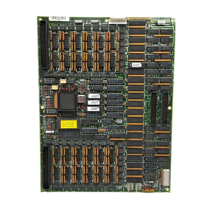
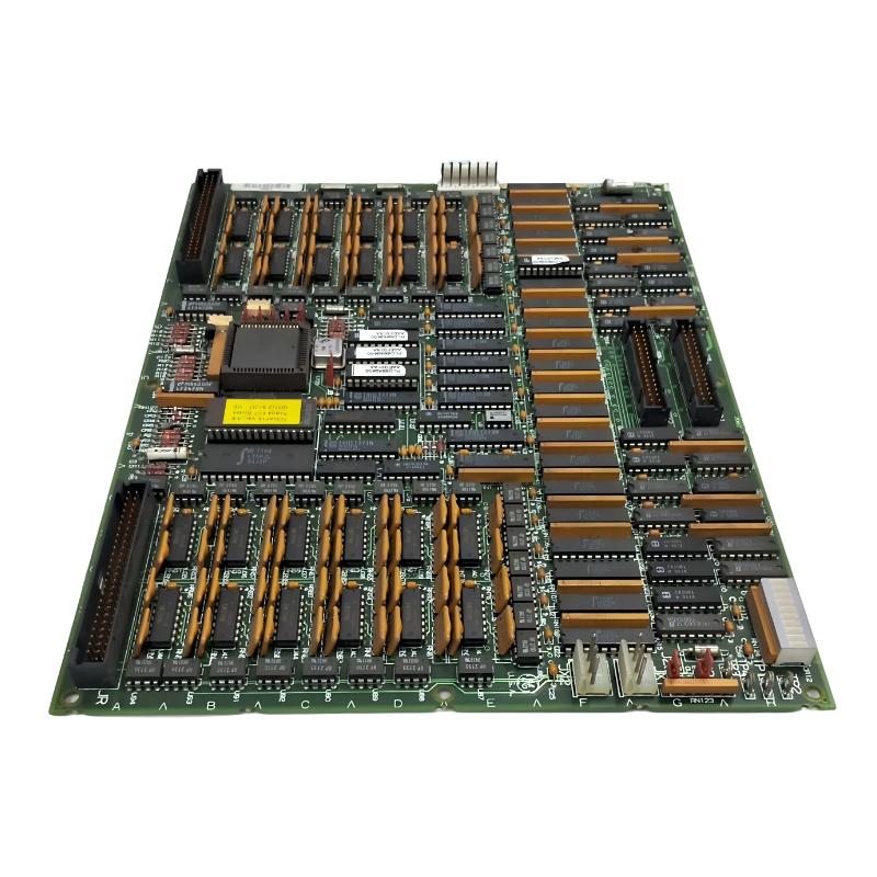
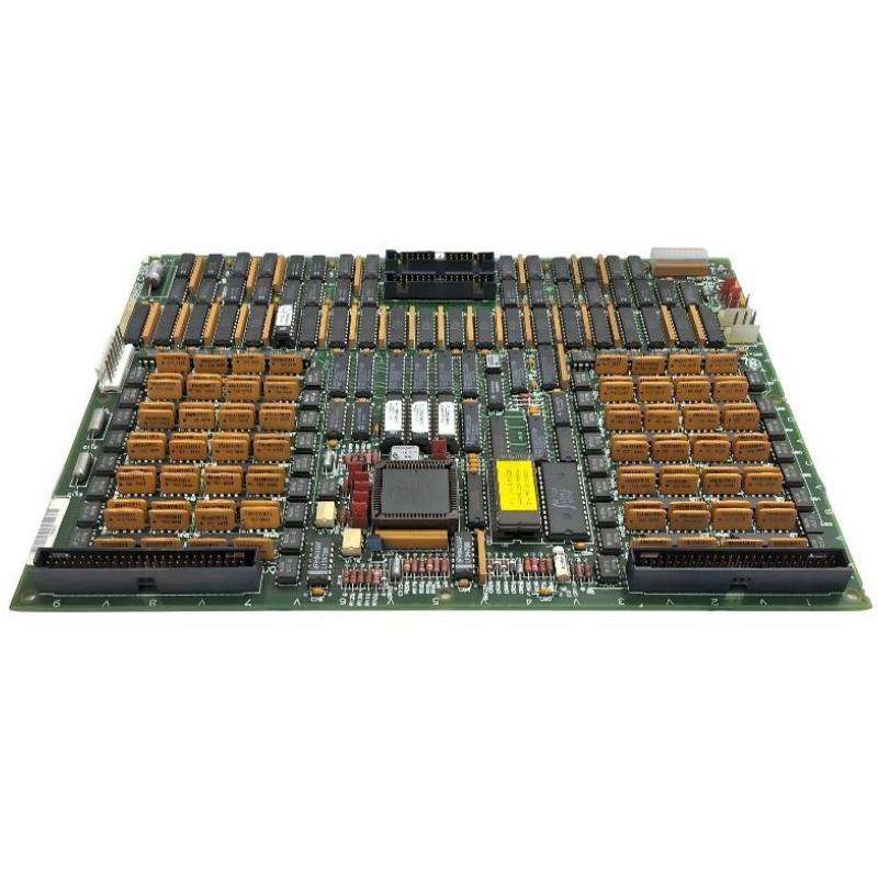
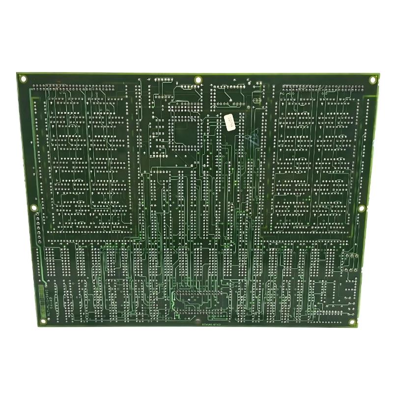
- GE
- DS215TCDAG1BZZ01A DS200TCDAG1BCB
- Digital I/O Board
- USA
- 265 × 180 × 32 mm
- 0.65 kg
- Xiamen, China
- New & In Stock
- T/T, PayPal, Western Union
- 1 Year
- 1-3 Working Days
- DHL, UPS, TNT, FedEx and EMS.
- 24-Hour Service
- COO
- 44
Our advantage

Global Logistics
We have a 10-year logistics and express cooperation agreement, so our products can be shipped to any place in the world.

Brand new and original
Our products are imported in bulk from the place of origin. Because of the cooperative relationship, our products are all original and 100% new.

24-hour service
We provide 7*24 hours service to our customers. We will be there whenever you need us.

Price advantage
All our products are priced very favorably because we have our own warehouse and supply.
| Company Information | |||
| [email protected] | |||
| Mobile | +8615980777398 | ||
| +8615980777398 | |||
| 15980777398 |
Product Overview
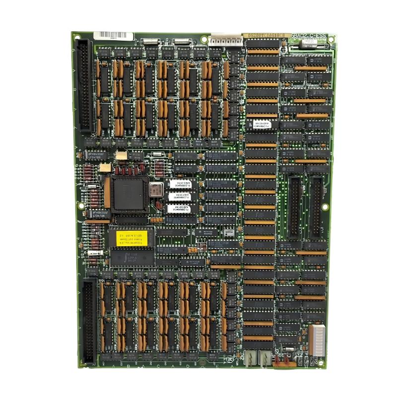
The GE DS215TCDAG1BZZ01A with the associated DS200TCDAG1BCB is a Digital I/O Board designed for compatible GE Mark V Speedtronic turbine control systems. The board belongs to the TCDA functional family and provides an important interface between field-level digital signals and the main turbine control architecture.
In an industrial turbine control system, a large number of operating conditions must be monitored continuously. Valve positions, relay states, auxiliary equipment status, permissive signals, alarm contacts, and other discrete conditions are typically represented as digital signals. The TCDA board provides the processing and interface functions required to transfer these signals between field terminal hardware and the Mark V control system.
The DS215TCDAG1BZZ01A represents a configured DS215-series board assembly, while DS200TCDAG1BCB identifies the associated functional Digital I/O Board configuration. The two identifiers are therefore important when identifying the correct replacement hardware for a legacy Mark V installation.
The board is designed to process both digital contact inputs and digital output information. It can receive field input signals through associated terminal boards and communicate processed information to the control system. It can also receive output commands from the control architecture and transfer them toward relay or other discrete output circuits.
This makes the board an active part of the control system rather than a simple passive terminal interface. Its processing, memory, communication, and configuration circuitry allow it to participate directly in the Mark V I/O architecture.
The specified GE DS215TCDAG1BZZ01A DS200TCDAG1BCB has dimensions of 265 × 180 × 32 mm and a weight of 0.65 kg.
Technical Specifications
| Parameter | Details |
|---|---|
| Manufacturer | GE General Electric |
| Model | DS215TCDAG1BZZ01A |
| Associated Board | DS200TCDAG1BCB |
| Functional Acronym | TCDA |
| Product Type | Digital I/O Board |
| System Family | GE Mark V Speedtronic |
| Primary Function | Digital input and output processing |
| Input Function | Digital contact input processing |
| Output Function | Digital relay and discrete output processing |
| Processing | On-board digital I/O processing |
| Communication | Mark V I/O network communication |
| Associated Terminal Boards | DTBA / DTBB and compatible Mark V terminal hardware |
| Application | Turbine control, monitoring and industrial automation |
| Installation | Mark V control cabinet / I/O core |
| Dimensions | 265 × 180 × 32 mm |
| Weight | 0.65 kg |
| Board Family | TCDA Digital I/O |
| Service Application | Maintenance, replacement and system restoration |
Function and Working Principle
The primary purpose of the DS215TCDAG1BZZ01A DS200TCDAG1BCB is to process discrete field signals and exchange them with the GE Mark V turbine control system.
Digital signals are widely used in turbine control because many field conditions can be represented by two basic states. A valve can be open or closed, a motor can be running or stopped, a relay can be energized or de-energized, and a protection contact can indicate normal or fault status.
The TCDA board processes these discrete signals so that the Mark V control logic can use them for sequencing, monitoring, permissives, alarms, and control decisions.
A simplified digital input path can be represented as:
Field Device → Field Wiring → DTBA/DTBB Terminal Board → TCDA Board → I/O Processing → Mark V Control Network → Control Processor
For a digital output command, the signal path operates in the opposite direction:
Mark V Control Logic → I/O Network → TCDA Board → Output Interface → Terminal Hardware → Relay / Solenoid / Discrete Field Device
This architecture allows the control system to monitor physical equipment and also issue commands to external devices.
The board can therefore participate in functions involving:
- Valve position monitoring
- Valve control commands
- Motor running status
- Relay status monitoring
- Solenoid control
- Pressure switch signals
- Limit switch signals
- Equipment permissive signals
- Alarm contacts
- Protection and trip indications
- Auxiliary equipment status
The processing of these signals is essential because the main controller does not normally connect directly to every individual field contact. The I/O architecture provides the necessary electrical and communication interface between field equipment and the control processor.
Role in Industrial Control Systems
The GE DS215TCDAG1BZZ01A plays an important role in the I/O portion of a Mark V turbine control system.
A turbine installation can contain hundreds or thousands of discrete signals. The control system must collect these signals, determine their current states, compare them with configured operating conditions, and use them within the appropriate control logic.
The TCDA board helps organize this process by acting as an electronic interface between terminal boards, I/O communication, and the Mark V control architecture.
Depending on the system configuration, the board can work alongside:
- GE Mark V control processors
- DTBA terminal boards
- DTBB terminal boards
- TCRA relay output boards
- TCQA control boards
- TCQE control boards
- TCEA interface boards
- STCA interface hardware
- UCPB control hardware
- TCPS power supply boards
- IONET communication hardware
These components form a complete control and I/O chain. The TCDA is particularly important because it provides the processing point where digital field information enters or leaves the control-system architecture.
A failure in this part of the system can therefore create symptoms at the operator interface even when the actual field device is operating correctly. Conversely, a faulty field contact or terminal connection can appear to be an I/O board failure.
For this reason, maintenance personnel should evaluate the complete signal path before replacing the board.
Digital Input Processing
Digital input processing is one of the principal functions of the DS200TCDAG1BCB.
Field switches and relay contacts generate discrete signals that represent equipment conditions. These signals are routed through the appropriate terminal hardware and then processed by the TCDA board.
Typical digital input applications include:
- Valve open and closed feedback
- Motor running indication
- Motor stopped indication
- Breaker status
- Relay status
- Pressure switch contacts
- Limit switch contacts
- Equipment fault contacts
- Emergency or protective status
- Auxiliary equipment permissives
Once the input reaches the board, the signal is converted into information that can be processed by the Mark V control architecture.
The controller can then use the information in control sequences. For example, a valve-open confirmation may be required before a subsequent turbine sequence is allowed to continue. Similarly, an auxiliary motor running signal may be required before another control function is enabled.
This makes reliable digital input processing essential for both automatic sequencing and operator monitoring.
Digital Output Processing
The DS215TCDAG1BZZ01A also participates in digital output functions within the Mark V architecture.
A digital output originates in control logic and is transferred through the control-system communication path to the appropriate I/O board. The TCDA board processes the output information and interfaces it with the appropriate output hardware.
Typical output applications include:
- Relay control
- Solenoid control
- Valve commands
- Auxiliary equipment control
- Alarm outputs
- Discrete permissive signals
- Equipment enable signals
Digital outputs allow software-based control logic to interact with physical equipment.
For example, the Mark V controller may determine that a particular valve should be energized. The command is transmitted through the I/O network to the relevant hardware, where the output circuit is activated and the field device receives the appropriate command.
IONET Communication
Communication between Mark V I/O boards and control processors is an important part of the TCDA architecture.
The TCDA board uses the Mark V I/O communication structure to exchange digital signal information with the wider control system. This communication path allows field information to reach the control processors without requiring every field signal to be directly connected to the main controller.
The general architecture can be represented as:
Field I/O → TCDA → I/O Network → Mark V Control Processor
For output functions:
Mark V Control Processor → I/O Network → TCDA → Field Output Interface
Communication faults can therefore affect multiple digital channels simultaneously. If several I/O signals disappear at the same time, technicians should consider communication, board power, network connections, and common interface circuits before assuming that multiple field devices have failed.
Mark V System Integration
The DS215TCDAG1BZZ01A is intended to operate as part of a larger GE Mark V system rather than as an independent control module.
The Mark V architecture separates control processing, I/O processing, terminal interfacing, power supply functions, and communication functions into different hardware assemblies.
The TCDA board occupies an important position within this architecture because it handles digital field information.
A typical system-level arrangement may include:
| System Layer | Typical Component | Primary Role |
|---|---|---|
| Field Layer | Switches, relays, valves, solenoids | Physical equipment and status signals |
| Terminal Layer | DTBA / DTBB | Field signal termination |
| I/O Layer | DS200TCDAG1BCB / TCDA | Digital signal processing |
| Communication Layer | IONET hardware | I/O data transmission |
| Control Layer | Mark V control processor | Control logic and sequencing |
| Operator Layer | HMI / operator station | Monitoring and operator commands |
This layered architecture makes it possible to troubleshoot a signal systematically from the field device to the control processor.
Compatible System Components
The DS215TCDAG1BZZ01A DS200TCDAG1BCB can be integrated with several components used in GE Mark V turbine control systems.
| Component | Type | Function |
|---|---|---|
| DS200TCDAG1B | Digital I/O Board Family | TCDA digital input/output processing |
| DTBA | Terminal Board | Provides field signal termination and interface |
| DTBB | Terminal Board | Interfaces digital field input signals |
| TCRA | Relay Output Board | Handles relay and discrete output functions |
| TCQA | Control Board | Provides control and system processing functions |
| TCQE | Control Board | Provides associated Mark V control functions |
| TCEA | Interface Board | Provides additional system interface functions |
| STCA | Interface Board | Supports Mark V control-system interfaces |
| UCPB | Control Processor Board | Provides control-system processing |
| TCPS | Power Supply Board | Provides system power |
The exact combination of components depends on the turbine model, control architecture, I/O core configuration, and application requirements.
Installation and System Integration
Correct installation of the GE DS215TCDAG1BZZ01A is important because the board interfaces with both control-system communication and field-level I/O hardware.
Before installation, technicians should verify the complete part number and compare the replacement board with the original assembly.
A recommended installation sequence includes:
- Place the turbine control system into the approved maintenance condition.
- Isolate the applicable power sources.
- Verify that hazardous voltage has been removed.
- Record the complete DS215TCDAG1BZZ01A part number.
- Record the DS200TCDAG1BCB identification.
- Document the original board position.
- Record all connector positions.
- Document jumper settings before removing the original board.
- Inspect the replacement PCB for physical damage.
- Check connectors for contamination or bent pins.
- Install the board into the correct I/O core position.
- Reconnect communication and field interface connections.
- Verify that all connectors are fully seated.
- Confirm correct board orientation.
- Restore power according to the approved commissioning procedure.
- Check board status indicators.
- Verify I/O communication.
- Verify digital input states.
- Perform controlled digital output testing.
- Confirm normal communication with the control system.
Electrostatic discharge precautions should be followed whenever the PCB is handled. The board should be held by its edges rather than by components, connectors, or conductive traces.
After installation, the technician should verify actual field signal behavior instead of relying only on the presence of power or status LEDs.
Hardware Configuration
The DS200TCDAG1BCB includes hardware configuration resources that can affect board operation.
Configuration hardware can include jumpers and programmable memory components. These resources allow the board to operate according to the requirements of the specific Mark V installation.
Before replacing an installed board, technicians should record:
- Jumper positions
- Memory device arrangement
- Board revision
- Firmware or programmable logic identification
- Connector configuration
- Board location
- Associated terminal-board connections
Incorrect configuration can result in communication problems, incorrect I/O states, or unexpected system behavior.
Replacement boards should therefore be evaluated as complete configured assemblies rather than only by the basic DS200TCDAG1B functional number.
Maintenance and Troubleshooting Considerations
When troubleshooting the DS215TCDAG1BZZ01A DS200TCDAG1BCB, a structured signal-path approach is recommended.
| Observed Condition | Possible Area to Check |
|---|---|
| One digital input is incorrect | Field switch, wiring, terminal connection and individual input channel |
| Several digital inputs fail together | Common power, terminal board, communication path or TCDA board |
| Digital input remains permanently active | Field contact, wiring short, input circuit or configuration |
| Digital input remains inactive | Field device, wiring, terminal board or input circuitry |
| Digital output does not activate | Control logic, I/O communication, output circuit or terminal hardware |
| Several outputs fail together | Power supply, communication, common interface or board-level fault |
| Intermittent I/O operation | Loose connectors, wiring, vibration, contamination or PCB condition |
| Loss of communication | IONET connections, board power, network hardware or TCDA communication interface |
| Board does not initialize | Power, configuration memory, hardware or communication problem |
A single-channel failure should not automatically be treated as evidence of complete board failure. The corresponding field device and terminal connection should be checked first.
When multiple channels fail simultaneously, common causes become more likely. These can include loss of board power, communication problems, common terminal connections, or a board-level hardware problem.
Intermittent faults require particular attention to connectors, wiring, vibration, contamination, thermal conditions, and mechanical mounting.
Diagnostic Indicators and Testing
The board’s diagnostic indicators can provide useful information during maintenance.
Technicians should observe the board during system startup and normal operation. Important observations may include:
- Power status
- Board initialization
- Communication activity
- I/O state changes
- Abnormal LED conditions
- Changes during field-device operation
However, indicator LEDs should not be used as the only diagnostic method. A board can show normal power status while an individual I/O channel, communication circuit, or external wiring path is defective.
The most reliable troubleshooting approach combines board diagnostics with field measurements, terminal-board checks, communication verification, and control-system status information.
Common Causes of I/O Problems
Digital I/O faults in legacy turbine control systems can originate from several areas.
Common causes include:
- Loose field wiring
- Damaged terminal connections
- Faulty field switches
- Incorrect relay operation
- Communication cable problems
- Loss of control power
- Incorrect jumper configuration
- Memory or firmware mismatch
- PCB component degradation
- Connector contamination
- Thermal stress
- Vibration-related connection problems
Because the TCDA board sits between the field devices and the control system, technicians should isolate the fault location before replacing the PCB.
Replacement Considerations
When selecting a replacement for the GE DS215TCDAG1BZZ01A, the complete part number should be checked rather than relying only on the general description “Digital I/O Board.”
The relevant identifiers include:
- DS215TCDAG1BZZ01A
- DS200TCDAG1BCB
- TCDA functional designation
- Hardware revision
- Firmware configuration
- Memory arrangement
- Jumper configuration
- I/O core location
The associated Mark V system should also be identified before selecting a replacement. Different turbine control configurations can use different combinations of I/O boards and terminal hardware.
For critical applications, the replacement board should be functionally tested and its configuration verified before the turbine is returned to normal operation.
Recommended Alternative Models
The following models are related to the GE Mark V Digital I/O and control architecture and may be useful for comparison or spare-parts planning. They should not automatically be treated as direct replacements without verifying the complete system configuration.
| Model | Type | Key Feature | Application |
|---|---|---|---|
| DS215TCDAG1BZZ01A | Digital I/O Board | Configured TCDA I/O assembly | GE Mark V turbine control |
| DS200TCDAG1BCB | Digital I/O Board | TCDA digital input/output processing | Mark V Speedtronic systems |
| DS200TCDAG1BDB | Digital I/O Board | Related TCDA hardware configuration | GE Mark V digital I/O |
| DS200TCDAG1BFD | Digital I/O Board | Related TCDA configuration | GE turbine control systems |
| DS200TCDAG1B | Digital I/O Board | Base TCDA functional family | Mark V I/O applications |
| DS215TCEAG1BZZ01A | Digital I/O Board | Related Mark V I/O architecture | GE turbine control |
| DS215TCQAG1BZZ01A | Control / I/O Board | Related control-system processing | GE Mark V installations |
Replacement recommendation: The closest identification match is the complete DS215TCDAG1BZZ01A DS200TCDAG1BCB configuration. Other TCDA variants may have different hardware revisions, memory arrangements, firmware, or configuration details and should therefore be verified before use.
Key Advantages
- Designed for GE Mark V Speedtronic turbine control systems
- Provides digital input and output processing
- Interfaces field contact signals with the control architecture
- Supports relay and discrete output functions
- Supports communication with Mark V I/O networks
- Allows field status information to be processed by turbine control logic
- Supports digital control commands to external equipment
- Provides a structured interface between terminal boards and control processors
- Suitable for legacy turbine control maintenance
- Useful for industrial automation spare-parts and replacement projects
Technical FAQs
What is the GE DS215TCDAG1BZZ01A?
The GE DS215TCDAG1BZZ01A is a configured Digital I/O Board for compatible GE Mark V Speedtronic turbine control systems. The associated board identification is DS200TCDAG1BCB.
What is the main function of the DS200TCDAG1BCB?
The DS200TCDAG1BCB provides digital input and output processing. It interfaces field contact information and discrete output commands with the Mark V control architecture.
What does TCDA mean?
TCDA is the functional acronym associated with the Mark V Digital I/O Board family. It identifies the board’s digital input/output role within the turbine control architecture.
What are the dimensions of the DS215TCDAG1BZZ01A?
The specified dimensions are 265 × 180 × 32 mm.
How much does the DS215TCDAG1BZZ01A weigh?
The specified weight for this product configuration is 0.65 kg.
Where is the DS215TCDAG1BZZ01A used?
It is used in compatible GE Mark V Speedtronic turbine control systems, particularly for digital field input and output processing.
What types of signals can the TCDA board process?
The board is designed for digital or discrete signals such as contact inputs, equipment status signals, relay states, valve indications, permissives, alarms, and control outputs.
What terminal boards are associated with the DS215TCDAG1BZZ01A?
Depending on the system configuration, the TCDA board can interface with Mark V terminal hardware such as DTBA and DTBB boards.
Does the DS215TCDAG1BZZ01A communicate with the main controller?
Yes. The TCDA participates in the Mark V I/O communication architecture, allowing processed field information to be exchanged with the main control system.
Can DS200TCDAG1BCB replace every DS200TCDAG1B variant?
No. Although the boards belong to the same functional TCDA family, individual revisions can have different hardware and configuration characteristics. The complete system configuration should be verified before replacement.
What should be checked before replacing this board?
Technicians should check the complete part number, board revision, memory arrangement, firmware, jumper positions, I/O core location, connector positions, terminal-board connections, and system configuration.
What are common symptoms of a TCDA-related problem?
Possible symptoms include incorrect digital input status, missing field signals, output commands that do not operate, intermittent I/O behavior, communication errors, or abnormal board diagnostics. Each symptom should be investigated through the complete field-to-controller signal path.
Conclusion
The GE DS215TCDAG1BZZ01A DS200TCDAG1BCB Digital I/O Board is an important component of compatible GE Mark V Speedtronic turbine control systems. As a member of the TCDA family, it provides the digital input and output processing required to connect field devices with the turbine control architecture.
The board can process discrete signals from switches, relays, valves, motors, protection devices, and auxiliary equipment while also supporting digital output commands for external control devices. Through the Mark V I/O communication architecture, it provides an organized path between field-level signals and the control processor.
The specified product configuration measures 265 × 180 × 32 mm and weighs 0.65 kg. Its application within an industrial control cabinet makes accurate part-number identification particularly important when planning maintenance or replacement.
The relationship between DS215TCDAG1BZZ01A and DS200TCDAG1BCB should be considered when sourcing replacement hardware. The DS215 number identifies the configured assembly, while the DS200TCDAG1BCB identifies the associated TCDA Digital I/O Board configuration.
For maintenance engineers, turbine-control specialists, and industrial automation system integrators, the correct replacement process should include verification of hardware revision, firmware, memory configuration, jumpers, connectors, terminal-board wiring, and I/O core location. A complete signal-path test should then be performed after installation.
When correctly matched with the appropriate Mark V terminal boards, communication hardware, control processors, and field devices, the GE DS215TCDAG1BZZ01A DS200TCDAG1BCB provides an effective digital I/O interface for legacy turbine control applications and supports reliable monitoring, sequencing, and discrete equipment control.