Product Overview
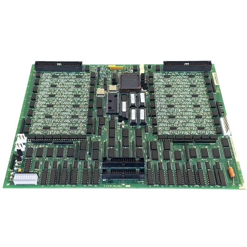
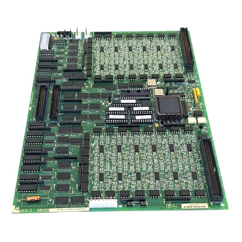
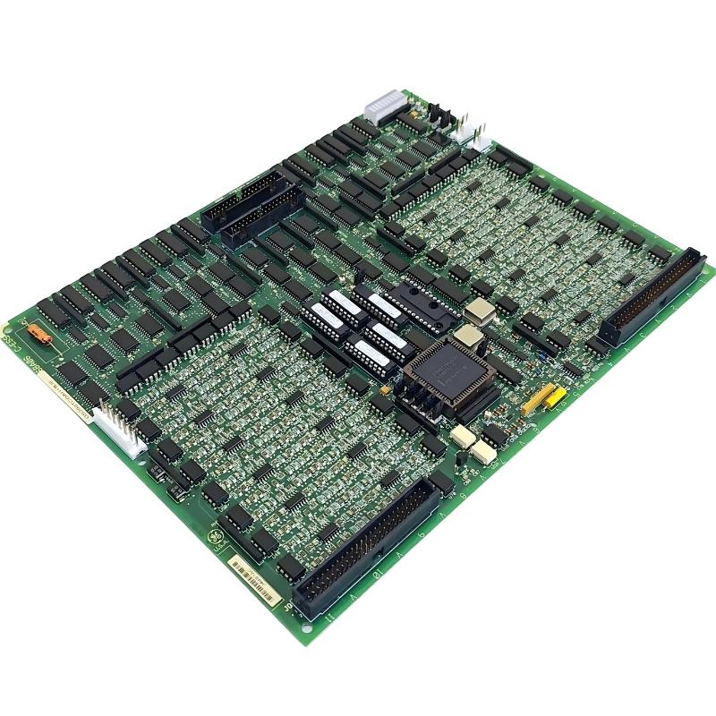
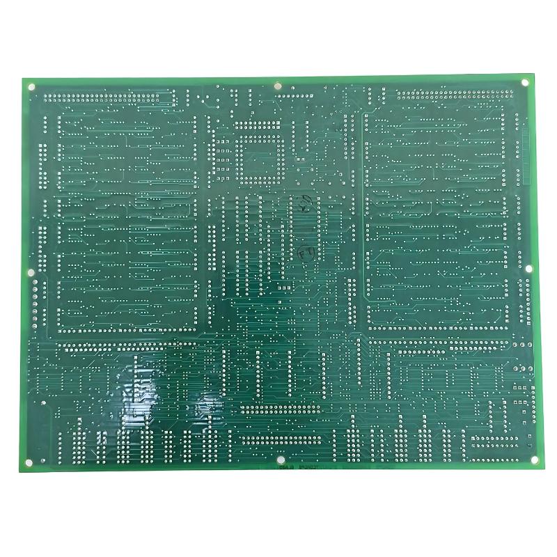
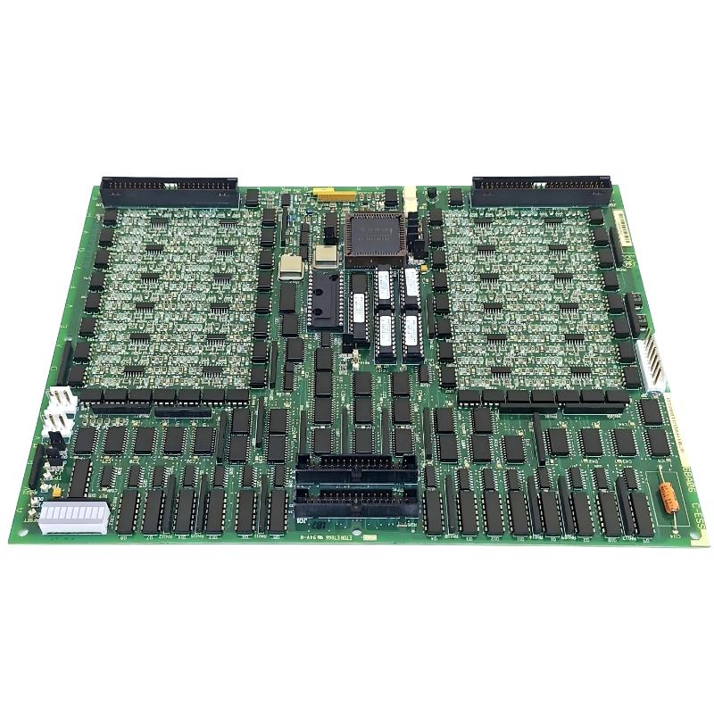
The GE DS200TCDAH1BGD Mark V Digital I/O Board is an active digital input/output interface used within compatible GE Mark V Speedtronic turbine control systems. Its primary function is to process digital contact inputs and digital contact-output signals and exchange the resulting information with other Mark V control hardware.
The TCDA board is associated with the digital I/O cores and interfaces with terminal boards and relay/interface boards. Digital contact inputs can be conditioned and time-tagged before being transmitted through the Mark V I/O network, while digital output commands are routed toward the appropriate relay or solenoid interface hardware.
The supplied dimensions for the DS200TCDAH1BGD are 330 × 280 × 25 mm, with a stated weight of 0.907 kg.
Technical Specifications
| Parameter |
Details |
| Manufacturer |
GE |
| Model |
DS200TCDAH1BGD |
| Product Type |
Mark V Digital I/O Board |
| Board Family |
TCDA |
| Control Platform |
GE Mark V Speedtronic |
| Main Function |
Digital Input and Output Processing |
| Input Type |
Digital / Contact Inputs |
| Output Type |
Digital Contact Outputs |
| Network Interface |
Mark V I/O Network |
| Application |
Turbine Control and Industrial Automation |
| Installation |
Mark V Digital I/O Core |
| Dimensions |
330 × 280 × 25 mm |
| Weight |
0.907 kg |
Function and Working Principle
The DS200TCDAH1BGD provides a digital signal interface within the Mark V control architecture.
A simplified input path is:
Field Contact → DTBA / DTBB Terminal Board → DS200TCDAH1BGD → I/O Network → Mark V Control Hardware
A simplified output path is:
Mark V Control Logic → DS200TCDAH1BGD → TCRA Relay Board → Relay / Solenoid Device
The board therefore operates in both directions:
- Digital inputs are acquired from field contact circuits.
- Digital outputs are transmitted toward relay or solenoid interfaces.
The TCDA circuitry conditions incoming contact signals, detects changes of state, and communicates the information through the I/O network. Contact-input inversion can be handled through software configuration rather than relying solely on physical wiring polarity.
Digital Input Function
Digital inputs generally represent discrete states rather than continuously varying measurements.
Examples include:
- Contact open
- Contact closed
- Switch status
- Limit-switch status
- Auxiliary contact status
- Equipment running indication
- Equipment trip indication
- Valve status
- Interlock status
- Alarm contact
The DS200TCDAH1BGD receives these signals from the appropriate terminal interfaces and processes them for use by the Mark V control system.
Digital Output Function
Digital outputs allow Mark V control logic to command external devices.
Depending on the system configuration, output commands can be associated with:
- Relays
- Solenoids
- Contactors
- Control circuits
- Auxiliary equipment
- Discrete actuators
The TCDA board routes digital output information toward the associated relay/interface boards rather than directly serving as the final field-load device in every application.
I/O Network Interface
The TCDA board communicates processed digital information through the Mark V I/O network.
This provides a path between the digital I/O hardware and other control-system electronics.
A simplified architecture is:
Field Devices
↓
DTBA / DTBB Terminal Interfaces
↓
DS200TCDAH1BGD
↓
I/O Network
↓
Control Hardware
For output signals:
Control Hardware
↓
I/O Network / TCDA
↓
TCRA Relay Interface
↓
Field Relay / Solenoid
This architecture separates field termination, signal processing, networking, and control logic.
TCDA Connector Functions
The board uses multiple interfaces for different signal groups.
| Connector |
General Function |
| JP |
Distributes board power from the applicable TCPS supply |
| JQ |
Connects to the DTBA terminal-board interface |
| JR |
Connects to the DTBB terminal-board interface |
| JO1 |
Routes contact-output signals toward the applicable TCRA interface |
| JO2 |
Routes additional contact-output signals toward the applicable TCRA interface |
| JX1 |
Shielded twisted-pair I/O network connection |
| JX2 |
Alternative I/O network connection |
The exact connector usage depends on the Mark V core and cabinet configuration.
Hardware Configuration
The TCDA board uses hardware jumpers for configuration and system operation.
The configuration can include functions related to:
- I/O network termination
- I/O network identification
- Stall-timer operation
- Factory-test functions
Because jumper settings can affect communication and board operation, they should be documented before replacing an existing board.
Do not assume that two visually similar TCDA boards have identical jumper configurations.
Software Configuration
Digital contact-input behavior can also depend on Mark V software configuration.
In particular, contact-input inversion can be defined through I/O configuration constants.
This means an apparently incorrect digital state may not necessarily indicate a defective board.
For example, a field contact that is physically closed may be interpreted differently depending on the configured input logic.
Role in the Mark V Control System
The DS200TCDAH1BGD sits between field digital signals and higher-level Mark V control logic.
A typical architecture is:
Field Contacts
↓
Terminal Boards
↓
DS200TCDAH1BGD Digital I/O Board
↓
I/O Network
↓
Mark V Control Processor
↓
Control / Alarm / Protection Logic
The board is therefore important for both monitoring and discrete control functions.
Industrial Applications
The DS200TCDAH1BGD can be used in compatible Mark V installations involving:
- Gas turbines
- Steam turbines
- Generator systems
- Turbine auxiliary equipment
- Industrial process equipment
- Discrete equipment monitoring
- Relay control
- Solenoid control
- Turbine sequencing
- Alarm and interlock systems
Digital I/O is particularly important for equipment states that need to be represented as clear ON/OFF or open/closed conditions.
Installation Guide
Step 1 – Verify the Exact Part Number
Before installation, verify:
- DS200TCDAH1BGD
- Complete revision suffix
- Mark V system configuration
- Board location
- Connector arrangement
- Jumper settings
- Associated terminal and relay boards
A board from the same general TCDA family should not automatically be treated as a drop-in replacement without checking the complete configuration.
Step 2 – Safely Isolate the System
Before replacing the board:
- Shut down the relevant equipment.
- Isolate electrical power.
- Follow site lockout/tagout procedures.
- Verify that applicable circuits are de-energized.
- Use ESD-safe handling procedures.
Digital I/O circuits may interface with external control voltages, relay circuits, and solenoids, so proper isolation is essential.
Step 3 – Document the Existing Board
Before removal:
- Photograph the board.
- Record connector positions.
- Record jumper settings.
- Document board location.
- Label applicable wiring.
- Record associated terminal boards.
- Record any diagnostic information.
This information can make post-installation troubleshooting substantially easier.
Step 4 – Remove the Existing Board
Carefully:
- Disconnect the I/O network cable.
- Disconnect signal connectors.
- Disconnect applicable power connections.
- Release mounting hardware.
- Remove the board.
- Place it on an ESD-safe surface.
Avoid pulling connectors by their wires.
Step 5 – Inspect the Replacement
Check the replacement DS200TCDAH1BGD for:
- Bent connector pins
- Damaged sockets
- Cracked components
- Burn marks
- Corrosion
- Contamination
- Mechanical damage
Compare its configuration with the original board before installation.
Step 6 – Verify Hardware Jumpers
Before powering the system:
- Compare jumper positions.
- Verify I/O network identification.
- Verify termination configuration.
- Check applicable timer settings.
- Confirm that factory-test jumpers are not incorrectly configured.
Incorrect jumper settings can cause communication or system-initialization problems.
Step 7 – Install the Board
Install the board by:
- Aligning it with the appropriate rack position.
- Securing the mounting hardware.
- Connecting the applicable power interface.
- Connecting DTBA/DTBB interfaces.
- Connecting output interfaces.
- Connecting the I/O network.
- Checking every connector for secure seating.
Commissioning Procedure
After installation, commissioning should proceed in stages.
Hardware Verification
Confirm:
- Board position
- Connector seating
- Jumper configuration
- I/O network connection
- Power connection
Digital Input Verification
Test representative field inputs:
- Open contact
- Closed contact
- Alarm contact
- Status contact
- Limit switch
Verify that the Mark V system displays the expected state.
Digital Output Verification
Where permitted by the operating procedure, test the appropriate output functions and confirm:
- Correct command
- Correct relay response
- Correct solenoid response
- Correct feedback indication
Testing should be performed under controlled conditions because output circuits may operate real equipment.
Common Failure Symptoms
| Symptom |
Possible Cause |
| Digital input does not change state |
Field contact or wiring fault |
| Input state is reversed |
Software inversion/configuration |
| Multiple inputs unavailable |
Connector, power, or board problem |
| Digital output does not operate |
Output path or relay-interface problem |
| I/O network communication fault |
Network connection or jumper configuration |
| Board not recognized |
Configuration or hardware problem |
| Intermittent digital status |
Loose connector or field wiring |
| Unexpected output |
Configuration or control-logic issue |
Troubleshooting Guide
Digital Input Does Not Change State
If a contact input remains fixed:
- Check the field device.
- Check field wiring.
- Check the DTBA/DTBB terminal interface.
- Inspect the JQ/JR connection.
- Check the TCDA board.
- Verify software input configuration.
- Review system diagnostics.
This approach helps determine whether the problem is in the field circuit or the digital I/O hardware.
Digital Input Is Reversed
If an ON signal appears as OFF, or an OFF signal appears as ON:
- Verify the field contact.
- Check wiring.
- Verify the terminal-board connection.
- Review the input inversion configuration.
- Confirm that the software configuration matches the intended field logic.
Do not replace the board simply because the displayed state is inverted.
Multiple Digital Inputs Fail
If many inputs fail simultaneously:
- Check the common power supply.
- Inspect JQ/JR connectors.
- Check the associated terminal board.
- Inspect the TCDA board.
- Review I/O network diagnostics.
- Check system configuration.
Multiple simultaneous failures generally warrant investigation of shared components first.
Digital Output Does Not Operate
If a commanded output does not activate:
- Verify that the Mark V control logic is issuing the command.
- Check the TCDA output interface.
- Inspect JO1/JO2 connections.
- Check the associated TCRA relay board.
- Inspect the external relay or solenoid circuit.
- Verify field power.
- Check for configuration or interlock conditions.
A failed actuator should not automatically be attributed to the TCDA board.
I/O Network Communication Fault
If the board does not communicate properly:
- Check the JX1/JX2 connection.
- Inspect shielded twisted-pair cabling.
- Verify I/O network identification.
- Check termination configuration.
- Inspect associated network hardware.
- Review Mark V diagnostics.
Hardware jumper settings can be important when investigating network-related problems.
Physical Inspection
Inspect the DS200TCDAH1BGD for:
- Burn marks
- Discolored components
- Damaged connectors
- Bent pins
- Corrosion
- Contamination
- Cracked solder joints
- Mechanical damage
Also inspect the surrounding cabinet for:
- Excessive temperature
- Dust accumulation
- Vibration
- Loose wiring
- Poor ventilation
Preventive Maintenance
Recommended maintenance includes:
- Periodic visual inspection
- Connector inspection
- I/O network cable inspection
- Terminal-board inspection
- Field-wiring inspection
- Jumper-configuration verification
- Cabinet cleaning
- Cooling-system inspection
- Review of recurring digital I/O alarms
For long-service Mark V installations, maintaining accurate board configuration records is particularly important.
Digital Signal Integrity
Digital signals may appear simple because they represent discrete states, but reliable operation still depends on the complete electrical path.
Important factors include:
Contact Quality
Dirty, oxidized, or mechanically damaged contacts can cause intermittent state changes.
Wiring
Loose or damaged field wiring can produce false status indications.
Electrical Noise
Noise can occasionally cause unwanted transitions in sensitive digital circuits.
Grounding
Poor grounding can affect signal stability and communication performance.
Configuration
Incorrect input inversion or I/O configuration can make a healthy circuit appear to operate incorrectly.
System Integration
The DS200TCDAH1BGD operates as part of a broader Mark V digital control system.
| Component |
Function |
| Field Contact |
Provides discrete equipment status |
| DTBA / DTBB |
Provides field termination |
| DS200TCDAH1BGD |
Processes digital I/O signals |
| TCRA |
Provides relay/output interface |
| I/O Network |
Transfers I/O information |
| Mark V Controller |
Executes control logic |
| Operator Interface |
Displays status and alarms |
| External Relay / Solenoid |
Performs commanded action |
This architecture means that troubleshooting should follow the complete signal path rather than focusing on the TCDA board alone.
Replacement Considerations
Before replacing a DS200TCDAH1BGD, document:
- Complete part number
- Board revision
- Existing board location
- Connector arrangement
- Jumper positions
- I/O network configuration
- Associated terminal boards
- Associated relay boards
- Existing diagnostic status
After replacement, verify both digital input and digital output functions.
Key Advantages
- Designed for compatible GE Mark V Speedtronic systems
- Provides digital input and output processing
- Interfaces with digital contact signals
- Supports relay and solenoid output paths
- Communicates through the Mark V I/O network
- Supports time-tagged contact-state information
- Suitable for turbine control and industrial automation
- Supplied dimensions: 330 × 280 × 25 mm
- Supplied weight: 0.907 kg
Technical FAQs
What is the GE DS200TCDAH1BGD?
The GE DS200TCDAH1BGD is a Mark V Digital I/O Board used to process digital contact inputs and outputs within compatible GE Speedtronic control systems.
What is the difference between digital and analog I/O?
Digital I/O represents discrete states such as ON/OFF or open/closed, while analog I/O represents continuously varying values such as temperature, pressure, or flow.
What does the TCDA board do with digital inputs?
It receives digital contact signals from associated terminal boards, conditions the signals, detects changes of state, and transfers the information through the Mark V I/O network.
Where do digital output signals go?
Depending on the system configuration, output signals can be routed from the TCDA board toward TCRA relay interfaces and ultimately to devices such as relays or solenoids.
What are the dimensions?
The supplied dimensions are 330 × 280 × 25 mm.
What is the weight?
The supplied weight is 0.907 kg.
Why can a digital input appear reversed?
Input inversion can be determined through software configuration. Therefore, an apparently reversed input does not necessarily indicate a hardware failure.
What can cause an I/O network communication problem?
Possible causes include incorrect network connections, damaged communication cabling, incorrect board identification, termination configuration problems, or associated Mark V network hardware faults.
Should the board be replaced when one digital input fails?
Not immediately. The field contact, wiring, terminal board, connector, software configuration, and associated I/O hardware should be checked first.
Conclusion
The GE DS200TCDAH1BGD Mark V Digital I/O Board is a key interface component for discrete signals in compatible GE Speedtronic turbine-control systems. It processes digital contact inputs from associated terminal interfaces and routes digital output commands toward relay and solenoid interface hardware while communicating I/O information through the Mark V network.
Successful installation requires careful attention to board identification, connector placement, jumper configuration, I/O network connections, field wiring, and software configuration. During troubleshooting, technicians should distinguish between field-device problems, terminal-board faults, communication issues, configuration errors, and actual TCDA hardware failures.
With supplied dimensions of 330 × 280 × 25 mm and a weight of 0.907 kg, the DS200TCDAH1BGD provides a substantial digital I/O interface for legacy turbine and industrial automation systems.