

ProductPRODUCT
Featured products



Contact Us
- GE
- DS200TCCAF1BDF
- MARK V Software PROM Kit
- USA
- 50 × 25 × 10 mm
- 0.02 kg
- Xiamen, China
- New & In Stock
- T/T, PayPal, Western Union
- 1 Year
- 1-3 Working Days
- DHL, UPS, TNT, FedEx and EMS.
- 24-Hour Service
- COO
- 50
Our advantage

Global Logistics
We have a 10-year logistics and express cooperation agreement, so our products can be shipped to any place in the world.

Brand new and original
Our products are imported in bulk from the place of origin. Because of the cooperative relationship, our products are all original and 100% new.

24-hour service
We provide 7*24 hours service to our customers. We will be there whenever you need us.

Price advantage
All our products are priced very favorably because we have our own warehouse and supply.
| Company Information | |||
| [email protected] | |||
| Mobile | +8615980777398 | ||
| +8615980777398 | |||
| 15980777398 |
Product Overview
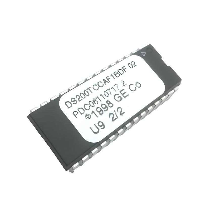
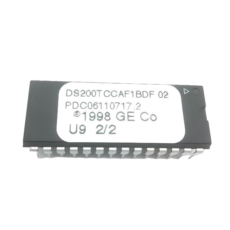
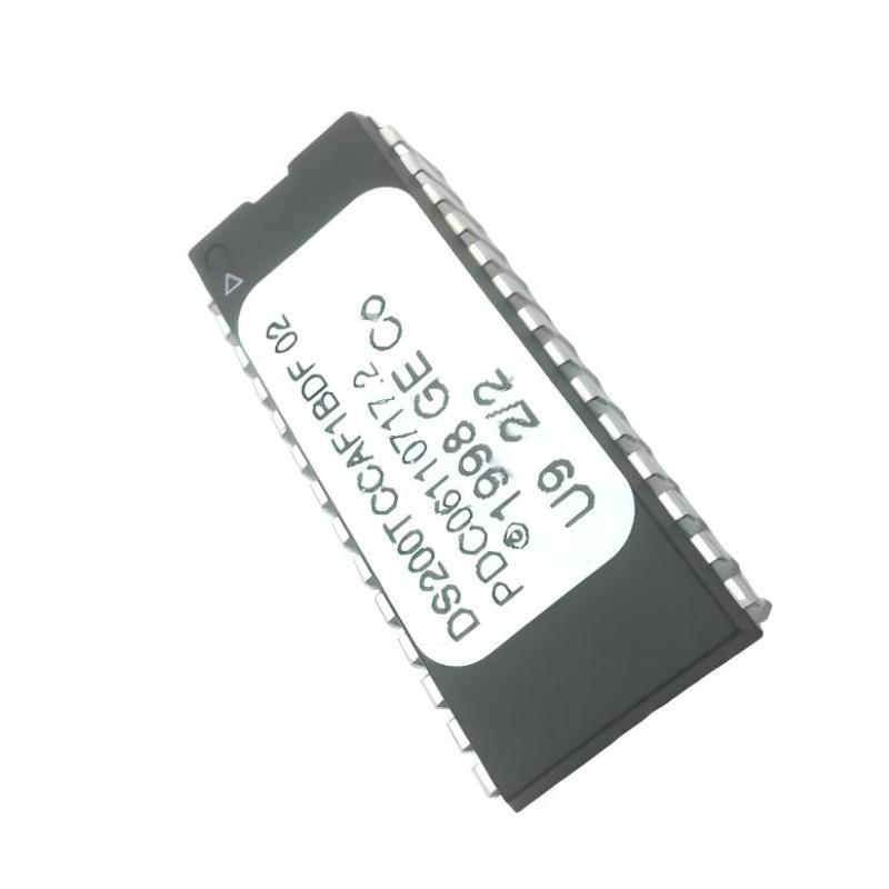
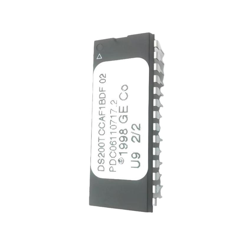
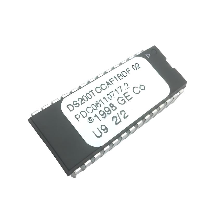
The GE DS200TCCAF1BDF Mark V Software PROM Kit is a firmware-storage component associated with the GE Mark V Speedtronic control system. Unlike a conventional I/O terminal board, this product is designed to store the software or firmware information required by compatible control hardware.
PROM devices are important in legacy industrial control systems because the stored program determines how associated control electronics execute their intended functions. The DS200TCCAF1BDF is therefore a configuration-critical component: installing the wrong PROM set, using an incorrect revision, or transferring devices incorrectly can prevent the control system from operating as intended.
The supplied physical specification for this product is 50 × 25 × 10 mm, with a stated weight of only 0.02 kg.
Technical Specifications
| Parameter | Details |
|---|---|
| Manufacturer | GE |
| Model | DS200TCCAF1BDF |
| Product Type | Mark V Software PROM Kit |
| Functional Description | Software PROM Set |
| Control Platform | GE Mark V / Speedtronic |
| Main Function | Firmware / Program Storage |
| Application | Industrial Turbine Control |
| Installation | Control Board / PROM Socket |
| Physical Format | Compact Programmable Read-Only Memory Set |
| Dimensions | 50 × 25 × 10 mm |
| Weight | 0.02 kg |
Function and Working Principle
The DS200TCCAF1BDF differs significantly from a typical GE Mark V circuit board.
Its primary function is program storage.
A simplified architecture is:
PROM Set → Mark V Control Hardware → Processor Executes Stored Program → Control / Monitoring / Protection Functions
A PROM contains non-volatile program information. Unlike volatile memory, the stored information is retained when system power is removed.
In a legacy turbine-control system, this stored program can define functions such as:
- Control sequences
- Monitoring logic
- Input interpretation
- Output behavior
- Alarm handling
- Protection functions
- System-specific operating routines
The exact software content depends on the particular PROM set and system configuration.
What Is a Software PROM Kit?
PROM stands for Programmable Read-Only Memory.
A PROM device stores information that the associated control hardware can read during operation.
A software PROM kit may contain one or more memory devices intended to work together with a specific control-board configuration.
This makes the DS200TCCAF1BDF fundamentally different from:
- Analog I/O boards
- Digital I/O boards
- Terminal boards
- Power-supply boards
- Communication boards
The component does not primarily provide field signal termination or electrical power. Instead, it provides the program information required by compatible Mark V control hardware.
Role in GE Mark V Systems
The Mark V system relies on dedicated control hardware and embedded software to perform turbine-control functions.
A simplified structure is:
Field Signals
↓
I/O Electronics
↓
Control Hardware
↓
PROM-Based Software
↓
Control Logic
↓
Turbine / Generator Equipment
The PROM content must correspond to the correct hardware revision and system configuration.
For this reason, PROM replacement should be treated as a configuration-sensitive maintenance procedure, not simply as a routine component swap.
Main Features
Non-Volatile Program Storage
The PROM retains its stored information without continuous power.
This makes it suitable for legacy control systems where firmware must remain available after shutdown or power loss.
Compact Construction
The supplied dimensions are:
50 × 25 × 10 mm
The supplied weight is:
0.02 kg
The extremely low weight is consistent with a small memory-device-based component rather than a conventional PCB assembly.
Mark V Application
The DS200TCCAF1BDF is associated with GE Mark V Speedtronic control equipment.
Because Mark V systems can contain hardware and software revisions specific to particular installations, exact part-number verification is essential before installation.
Industrial Applications
The DS200TCCAF1BDF is intended for compatible industrial control applications involving legacy GE Mark V systems.
Potential applications include:
- Gas turbine control
- Steam turbine control
- Power-generation systems
- Generator control
- Turbine protection
- Industrial rotating equipment
- Legacy Speedtronic installations
Installation Guide
Step 1 – Confirm the PROM Identification
Before installation, verify:
- DS200TCCAF1BDF part number
- PROM device markings
- Software revision
- Hardware compatibility
- Original system configuration
Do not install a PROM based only on physical appearance.
Two devices can look identical while containing different software versions.
Step 2 – Record the Existing Configuration
Before removing the original PROM set:
- Record the location of each device.
- Record device markings.
- Photograph the original installation.
- Note orientation.
- Record socket identification.
- Document the associated control-board part number.
This information can be extremely valuable if troubleshooting is required after installation.
Step 3 – Power Down the System
PROM replacement should be performed only after the applicable control hardware has been safely de-energized.
Follow:
- Site lockout/tagout procedures
- Electrical safety procedures
- ESD precautions
- Manufacturer-approved maintenance practices
Never remove or insert a PROM into an energized socket unless the specific hardware is explicitly designed and approved for such a procedure.
Step 4 – Remove the Existing PROM
Use appropriate PROM extraction equipment.
When removing the device:
- Avoid bending pins.
- Avoid touching exposed contacts unnecessarily.
- Do not pry aggressively against the PCB.
- Keep track of the device orientation.
- Place the removed PROM in an ESD-safe container.
Step 5 – Verify Orientation
PROM devices are orientation-sensitive.
Before insertion, verify:
- Pin-1 position
- Socket orientation
- Device notch or identification mark
- Board markings
Incorrect orientation can cause hardware malfunction or physical damage when power is restored.
Step 6 – Install the DS200TCCAF1BDF
Carefully:
- Align the PROM with the socket.
- Verify pin alignment.
- Ensure no pins are bent underneath the device.
- Press the PROM evenly into the socket.
- Confirm that the device is fully seated.
Do not force the device into the socket.
Commissioning Procedure
After installation:
Hardware Check
Verify:
- PROM seating
- Correct orientation
- No bent pins
- Correct socket location
- Correct control-board identification
Power-Up
Restore power according to the approved system procedure.
Observe:
- Startup behavior
- Control-system diagnostics
- Processor status
- Alarm indications
- Communication status
Functional Verification
Confirm that:
- The control system recognizes the expected configuration.
- No unexpected software or configuration alarms appear.
- Normal control functions are available.
- Associated I/O functions behave correctly.
Common Failure Symptoms
| Symptom | Possible Cause |
|---|---|
| Controller fails to start | Incorrect or damaged PROM |
| Software/configuration alarm | Wrong revision or PROM set |
| Unexpected control behavior | Incorrect software content |
| Processor fault | Poor PROM connection |
| System does not recognize program | Incorrect device or socket |
| Intermittent operation | Poor contact or damaged pins |
| Multiple functions unavailable | Incompatible software/hardware combination |
Troubleshooting Guide
Controller Does Not Start
If the control hardware fails to start after PROM replacement:
- Power down safely.
- Verify PROM orientation.
- Check the device location.
- Inspect pins for bending.
- Confirm the part number.
- Verify software revision.
- Compare with the original configuration.
Do not repeatedly power-cycle a system when the PROM installation itself is in question.
Software or Configuration Alarm
If the system reports a software-related alarm:
- Confirm the PROM identification.
- Verify revision compatibility.
- Check whether the complete PROM set has been installed.
- Verify socket locations.
- Compare the replacement configuration with the original.
A configuration mismatch can produce system-level symptoms even when the PROM device itself is physically healthy.
Intermittent Operation
Intermittent operation can result from:
- Poor socket contact
- Oxidized contacts
- Bent pins
- Loose PROM seating
- Mechanical vibration
- Socket degradation
Inspect the physical installation before assuming that the stored software has become corrupted.
Unexpected Control Behavior
If the system starts but behaves differently from the original configuration:
- Verify the PROM revision.
- Confirm the correct PROM set.
- Check associated board revision.
- Review system configuration.
- Compare installed devices against maintenance records.
Software mismatch should be considered when the hardware appears normal but system behavior changes after replacement.
PROM Handling Precautions
PROM devices are small and relatively lightweight, but they require careful handling.
Avoid:
- Static discharge
- Excessive mechanical force
- Bent pins
- Incorrect orientation
- Improper storage
- Contamination of contacts
- Installing an unidentified device
Recommended handling practices include:
- Use ESD-safe workstations.
- Wear an appropriate grounding strap.
- Store removed devices in conductive or ESD-safe packaging.
- Keep identification labels intact.
- Document device location and revision.
Physical Inspection
Inspect the DS200TCCAF1BDF for:
- Bent pins
- Cracked package
- Damaged markings
- Contaminated contacts
- Physical deformation
- Signs of overheating
Also inspect the associated PROM socket for:
- Broken contacts
- Corrosion
- Mechanical damage
- Loose socket connections
- Contamination
A damaged socket can cause symptoms that appear to originate from the PROM itself.
Preventive Maintenance
PROM devices generally require less routine maintenance than active electronic boards, but configuration management is extremely important.
Recommended practices include:
- Maintain software revision records.
- Keep spare PROMs properly labeled.
- Store spare devices in ESD-safe packaging.
- Record the original device locations.
- Document compatible control-board revisions.
- Maintain backup configuration information.
- Inspect PROM sockets during major control-system maintenance.
For legacy systems, accurate software-revision records can be just as important as hardware documentation.
System Integration
The DS200TCCAF1BDF should be considered part of a larger control-system configuration.
| Component | Function |
|---|---|
| Field Sensors | Provide process information |
| I/O Boards | Acquire and condition signals |
| Control Processor | Executes control operations |
| PROM Set | Stores required software/firmware |
| Communication Hardware | Transfers control-system data |
| Operator Interface | Provides monitoring and commands |
| Protection Logic | Provides equipment protection |
The correct interaction between software, processor hardware, I/O hardware, and configuration data is essential for reliable turbine operation.
Key Advantages
- Designed for compatible GE Mark V control systems
- Provides non-volatile program storage
- Compact physical format
- Very low weight
- Supports legacy turbine-control applications
- Simplifies replacement of compatible software-memory devices
- Allows control software to remain available after power removal
- Suitable for maintenance of existing Mark V installations
Technical FAQs
What is the GE DS200TCCAF1BDF?
The GE DS200TCCAF1BDF is a Mark V Software PROM Kit associated with GE Speedtronic control equipment.
What does PROM mean?
PROM means Programmable Read-Only Memory. It is a type of non-volatile memory used to retain stored program information without continuous electrical power.
Is the DS200TCCAF1BDF an I/O board?
No. It is a software-memory component rather than a conventional analog, digital, or terminal I/O board.
Why is the software revision important?
The stored software must be compatible with the associated control hardware and system configuration. An incorrect revision can result in startup faults, configuration alarms, or unexpected system behavior.
What are the dimensions?
The supplied dimensions are 50 × 25 × 10 mm.
What is the weight?
The supplied weight is 0.02 kg.
Can the PROM be installed in any Mark V socket?
No. The correct socket and orientation depend on the associated hardware and system configuration. The original installation and applicable system documentation should be used to determine the correct location.
What can cause a PROM-related failure?
Potential causes include incorrect software revision, incorrect device placement, bent pins, poor socket contact, ESD damage, physical damage, or incompatibility between the PROM and associated control hardware.
Conclusion
The GE DS200TCCAF1BDF Mark V Software PROM Kit is a compact but configuration-critical component for compatible GE Mark V Speedtronic control systems. Its role is fundamentally different from that of a conventional control PCB: it provides the non-volatile program information required by associated control hardware.
Because the component contains software rather than simply providing electrical connections, part-number verification, software-revision control, correct device orientation, socket identification, and ESD-safe handling are essential during replacement.
With supplied dimensions of 50 × 25 × 10 mm and a weight of 0.02 kg, the DS200TCCAF1BDF is physically small, but its software content can have a significant effect on system operation. For legacy Mark V maintenance, careful configuration management and systematic commissioning are therefore essential when replacing this PROM kit.