

ProductPRODUCT
Featured products
Contact Us
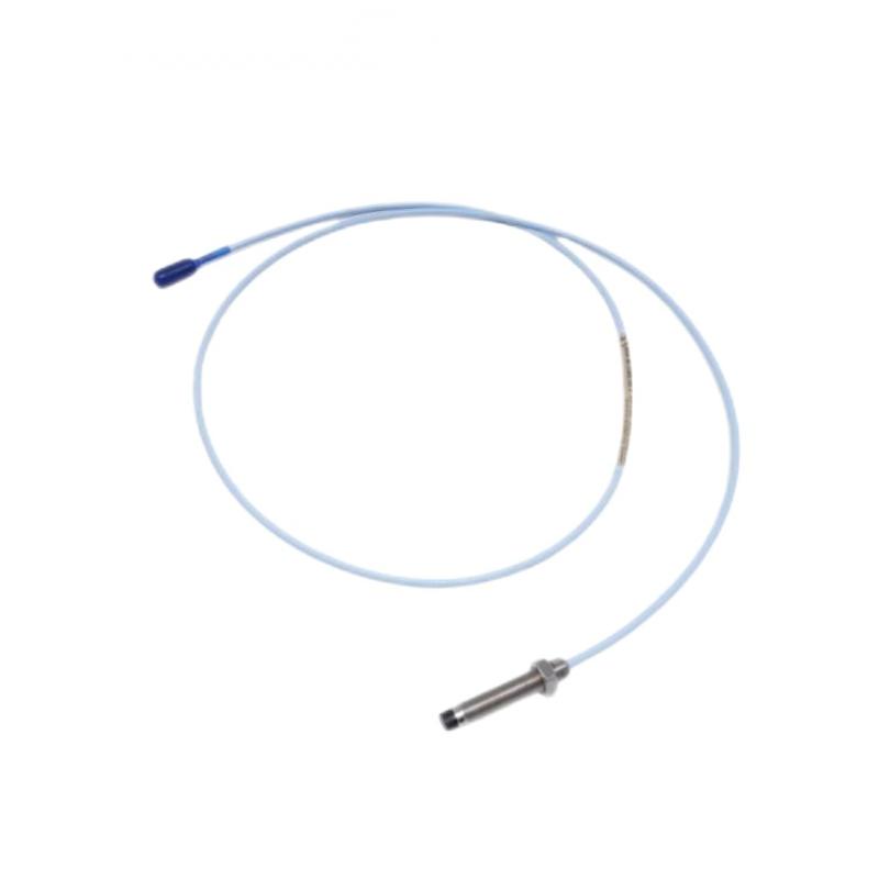
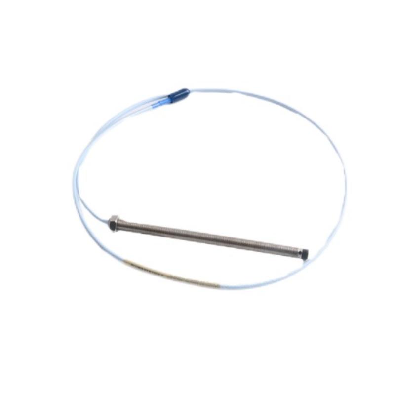
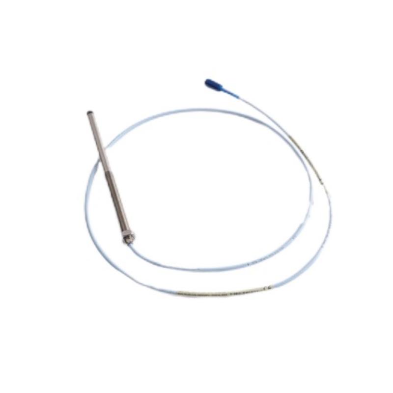
- Bently Nevada
- 330910-05-10-10-02-00
- 3300 NSv Proximity Probe
- USA
- 100 mm
- 1kg
- Xiamen, China
- New & In Stock
- T/T, PayPal, Western Union
- 1 Year
- 1-3 Working Days
- DHL, UPS, TNT, FedEx and EMS.
- 24-Hour Service
- COO
- 2
Our advantage

Global Logistics
We have a 10-year logistics and express cooperation agreement, so our products can be shipped to any place in the world.

Brand new and original
Our products are imported in bulk from the place of origin. Because of the cooperative relationship, our products are all original and 100% new.

24-hour service
We provide 7*24 hours service to our customers. We will be there whenever you need us.

Price advantage
All our products are priced very favorably because we have our own warehouse and supply.
| Company Information | |||
| [email protected] | |||
| Mobile | +8615980777398 | ||
| +8615980777398 | |||
| 15980777398 |
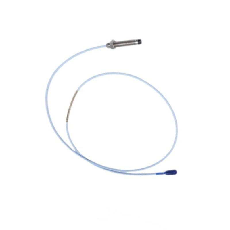
Bently Nevada 330910-05-10-10-02-00 Proximity Probe
1. Product Overview
The Bently Nevada 330910-05-10-10-02-00 is an armored proximity probe in the 3300 NSv product series, designed for non-contact measurement of shaft displacement and vibration-related movement in compatible rotating machinery monitoring systems.
The 3300 NSv design is intended for applications where installation clearance is limited or where the geometry of a smaller shaft makes probe selection particularly important. The probe uses an M10 × 1 metric thread and an armored construction, making it suitable for installations designed around that mounting interface.
Its ordering code indicates a 50 mm unthreaded length, a 100 mm overall case length, a 1.0 m total probe length, a miniature coaxial ClickLoc connector with standard cable, and an approval option marked 00.
The probe is not a stand-alone monitor. It operates as part of a compatible measurement channel that includes the appropriate driver electronics and monitoring equipment.
2. Technical Parameters
| Parameter | Specification |
|---|---|
| Product model | 330910-05-10-10-02-00 |
| Brand | Bently Nevada |
| Product series | 3300 NSv |
| Product type | Armored proximity probe |
| Measurement principle | Eddy-current sensing |
| Mounting thread | M10 × 1 |
| Unthreaded length | 50 mm |
| Overall case length | 100 mm |
| Total probe length | 1.0 m (1000 mm / approximately 39.4 in) |
| Connector | Miniature coaxial ClickLoc |
| Cable type | Standard cable |
| Cable impedance | 75 Ω coaxial |
| Probe construction | Armored |
| Probe-tip material | PPS, subject to configuration verification |
| Probe-case material | AISI 304 stainless steel, subject to configuration verification |
| Target material | Suitable conductive target; system performance is specified using the approved target material |
| Typical linear range | Approximately 1.5 mm (60 mils) for the compatible NSv measurement system |
| Typical scale factor | Approximately 7.87 V/mm (200 mV/mil), subject to system specifications |
| Frequency response | Typically up to 10 kHz for the compatible measurement system |
| Agency approval option | 00 — approval option not required |
| Overall dimensions | 100 mm case length; 50 mm unthreaded length; 1.0 m total probe length |
| Weight | Exact net weight not confirmed; verify the supplied probe’s weight and packaging details |
| Typical applications | Shaft vibration, displacement, and position monitoring |
| System requirements | Compatible 3300 NSv driver and monitoring equipment |
| Installation type | Fixed threaded mounting at an approved measurement point |
Important dimensional note: The 50 mm unthreaded length, 100 mm case length, and 1.0 m total probe length describe different aspects of the configuration. They should not be added together as though they were three separate body lengths. The exact dimensional drawing should be checked before ordering a replacement.
3. Model Number Configuration
The complete model number identifies the probe’s mechanical dimensions, cable length, connector configuration, and approval option.
| Code | Meaning | Specification |
|---|---|---|
| 330910 | Base model | 3300 NSv armored proximity probe with M10 × 1 thread |
| 05 | Unthreaded-length option | 50 mm |
| 10 | Overall case-length option | 100 mm |
| 10 | Total-length option | 1.0 m |
| 02 | Connector and cable option | Miniature coaxial ClickLoc connector, standard cable |
| 00 | Agency approval option | Not required |
When replacing an existing probe, the entire ordering code should be checked. A model with the same base number but a different unthreaded length, case length, cable length, or connector option may not fit the installation or meet the existing system’s requirements.
4. Product Introduction
4.1 Non-contact measurement
The 330910 probe uses eddy-current sensing to measure the gap between the probe tip and a conductive target. When the shaft moves relative to the fixed probe, the gap changes and produces a corresponding electrical response.
Compatible driver electronics convert this response into a measurement signal for the machinery monitoring system. The resulting data can be used to observe shaft displacement and vibration-related movement.
Because the sensing method does not require direct contact with the rotating shaft, the probe avoids normal contact wear during operation.
4.2 Narrow-side-view design
The 3300 NSv family is designed for applications where surrounding metal surfaces and restricted mounting geometry can affect proximity measurements. Its narrow-side-view characteristics make it useful for certain small-shaft and restricted-clearance installations.
This is particularly relevant in machinery where the probe must be installed within a limited counterbore or close to nearby metallic surfaces. The exact suitability depends on the shaft diameter, probe position, mounting geometry, and measurement requirements.
4.3 Armored mechanical construction
The armored design provides additional protection around the probe’s cable section. In an industrial installation, this can help reduce the risk of incidental mechanical damage during installation, inspection, or routine maintenance.
Armor does not remove the need for proper cable routing. Excessive bending, pulling, twisting, and exposure to temperatures outside the specified limits must still be avoided.
4.4 Defined mechanical configuration
This model combines a 50 mm unthreaded section with a 100 mm overall case length and a 1.0 m total probe length. These dimensions help engineers identify a suitable mounting arrangement and determine whether the probe can reach the intended measurement point.
The mounting thread and dimensions should always be compared with the existing installation drawing before procurement.
4.5 Part of a complete monitoring system
The probe is only one component of a proximity measurement channel. The complete channel normally requires a compatible driver, the appropriate interconnection arrangement, and monitoring electronics.
The probe, cable, and driver must be matched correctly to achieve the intended electrical response and measurement performance.
5. Product Applications
5.1 Steam and gas turbines
Proximity probes can be used on suitable turbine installations to monitor shaft displacement and vibration-related movement. Continuous measurements help operators observe changes during startup, load changes, steady operation, and shutdown.
The required probe location and measurement range depend on the turbine’s mechanical design and monitoring strategy.
5.2 Centrifugal compressors
Compressors used in power generation, gas processing, refrigeration, and manufacturing may require continuous shaft monitoring. The 3300 NSv design can be useful where a compact probe arrangement is needed around a smaller shaft or a restricted mounting location.
The measurement signals can be reviewed alongside speed, load, operating temperature, and historical trends.
5.3 Process gas compressors
In process plants, an unexpected compressor shutdown can interrupt production and increase maintenance costs. A correctly configured proximity measurement channel can provide ongoing shaft-related information to the machinery monitoring system.
The probe should be selected according to the required shaft measurement, environmental limits, and compatibility of the existing monitoring equipment.
5.4 Industrial pumps
Pumps used in water treatment, chemical processing, and industrial utilities may require shaft displacement measurements at selected locations. Where the pump and monitoring arrangement support proximity sensing, the probe can contribute to condition monitoring.
The installation must account for available clearance, the target material, and the mounting requirements.
5.5 Electric motors
On suitable motors, proximity measurements can provide information about shaft movement relative to a fixed mounting point. These readings can be evaluated with bearing temperature, speed, load, and other operating indicators.
Probe selection should be based on the motor’s monitoring requirements rather than the product’s physical fit alone.
5.6 Gearboxes and rotating equipment
Some gearboxes and transmission assemblies require shaft-position or vibration-related measurements. A compatible proximity probe can support such applications when the target geometry and system design are appropriate.
The probe should be mounted at the specified measurement point to ensure that the resulting readings reflect the intended shaft movement.
5.7 Power generation and heavy industry
Power plants and heavy industrial facilities often use continuous monitoring on critical rotating machinery. A proximity probe can form part of the monitoring channel for an approved turbine, compressor, or other rotating asset.
The data can support maintenance planning and machinery protection when interpreted by the correct monitoring system.
5.8 Predictive maintenance
Repeated shaft measurements allow maintenance personnel to compare present readings with historical operating trends. Changes in the readings may indicate a need to inspect the machine, verify operating conditions, or investigate other possible causes.
The probe itself does not identify every fault. Accurate diagnosis requires suitable monitoring equipment, correct configuration, and engineering assessment.
6. Main Product Advantages
6.1 Non-contact sensing
The probe measures shaft movement without touching the rotating target during normal operation. This avoids contact-related sensor wear and supports continuous measurement.
6.2 Compact metric mounting
The M10 × 1 threaded configuration provides a defined metric mounting interface. It is useful where the machine housing and installation drawing are designed for this thread size.
6.3 Armored cable protection
The armored construction offers additional mechanical protection for the cable section. This can help reduce damage associated with routine handling or incidental contact in suitable industrial installations.
6.4 Clearly defined installation dimensions
The 50 mm unthreaded length and 100 mm case length provide useful reference dimensions for checking mounting depth and clearance. The 1.0 m total length identifies the selected probe-length configuration.
6.5 Suitable for restricted-clearance installations
The NSv design is intended for applications where probe clearance and nearby metal surfaces require particular attention. This can make it useful for selected smaller-shaft installations and compact machinery layouts.
6.6 Supports continuous monitoring
When connected to compatible driver and monitoring equipment, the probe can provide ongoing measurements rather than relying solely on periodic manual inspections.
6.7 Helps support maintenance planning
Historical measurement trends can help maintenance teams determine whether a machine’s behavior has changed and whether additional investigation is warranted.
6.8 Configuration-specific replacement
The complete ordering code helps distinguish this model from other probes in the same family. Matching the entire code reduces the risk of choosing a replacement with the wrong dimensions, cable length, connector, or approval option.
7. Installation and Maintenance Recommendations
1. Verify the complete model number. Check all suffixes against the existing probe and the approved equipment documentation.
2. Confirm the mounting thread. Ensure that the mounting point accepts an M10 × 1 threaded probe.
3. Check mounting dimensions. Verify the 50 mm unthreaded length and 100 mm case length against the installation drawing.
4. Confirm the probe gap. Follow the instructions for the compatible driver and monitoring system rather than relying on a generic gap setting.
5. Check target suitability. Ensure that the shaft or target material and geometry meet the requirements of the measurement system.
6. Inspect the connector and cable. Verify the miniature coaxial ClickLoc connector and standard cable configuration.
7. Protect the cable. Avoid excessive bending, tension, twisting, and contact with hot or sharp surfaces.
8. Confirm the complete measurement channel. The probe, driver, cable arrangement, and monitor must be compatible.
9. Verify the signal after installation. Check the measurement channel and required calibration settings before placing the equipment into normal service.
10. Keep replacement records. Record the full part number, installation location, and commissioning details for future maintenance.
8. Five Related Models in the Same Series
The following models are related 3300 NSv proximity probes. Their base configurations are shown for comparison; the complete ordering code determines the actual dimensions, cable length, connector, and approval option.
| Model | Series | Main configuration | Dimensions | Weight (kg) |
|---|---|---|---|---|
| 330903 | 3300 NSv | M8 × 1 thread, without armor | Depends on the ordered configuration | Not confirmed |
| 330904 | 3300 NSv | M8 × 1 thread, with armor | Depends on the ordered configuration | Not confirmed |
| 330905 | 3300 NSv | M10 × 1 thread, without armor | Depends on the ordered configuration | Not confirmed |
| 330908 | 3300 NSv | 3/8-24 UNF thread, without armor | Depends on the ordered configuration | Not confirmed |
| 330909 | 3300 NSv | 3/8-24 UNF thread, with armor | Depends on the ordered configuration | Not confirmed |
These models share the general purpose of proximity measurement, but they differ in mounting interface and construction. They should not be treated as direct substitutes without checking the mechanical and electrical requirements.
9. Five Other Models from the Same Brand
The following models represent other proximity probes, transducer-system components, and monitoring hardware. They have different functions, so they are related product options rather than automatic replacements for the 330910 probe.
| Model | Product series | Main function | Dimensions | Weight (kg) |
|---|---|---|---|---|
| 330901 | 3300 NSv | 1/4-28 UNF proximity probe without armor | Depends on the ordered configuration | Not confirmed |
| 330902 | 3300 NSv | 1/4-28 UNF proximity probe with armor | Depends on the ordered configuration | Not confirmed |
| 330980 | 3300 XL NSv | Proximitor sensor for a compatible NSv transducer system | Depends on mounting and system configuration | Not confirmed |
| 330100 | 3300 XL | Extension cable family for compatible transducer arrangements | Depends on cable length and connector configuration | Not confirmed |
| 3500/42M | 3500 monitoring system | Machinery monitoring module for supported vibration and position inputs | Depends on the specified hardware arrangement | Not confirmed |
The probe, extension cable, Proximitor sensor, and monitoring module serve different roles. Before selecting any of these products, verify the complete measurement-channel design and electrical compatibility.
10. Purchasing Checklist
| Item | Required specification or check |
|---|---|
| Full model number | 330910-05-10-10-02-00 |
| Brand | Bently Nevada |
| Series | 3300 NSv |
| Thread | M10 × 1 |
| Unthreaded length | 50 mm |
| Overall case length | 100 mm |
| Total probe length | 1.0 m |
| Construction | Armored |
| Connector | Miniature coaxial ClickLoc |
| Cable | Standard cable |
| Approval option | 00 — not required |
| Dimensions | Confirm against the model-specific drawing |
| Weight | Net weight not confirmed; request verified product weight in kg |
| Driver compatibility | Confirm compatibility with the installed NSv system |
| Replacement check | Match mounting, cable, connector, and measurement requirements |
11. Product Summary
The Bently Nevada 330910-05-10-10-02-00 is an armored 3300 NSv proximity probe with an M10 × 1 mounting thread, 50 mm unthreaded length, 100 mm case length, and 1.0 m total probe length. It uses a miniature coaxial ClickLoc connector with standard cable.
Its principal role is to provide non-contact shaft-displacement measurements in compatible rotating machinery monitoring systems. The NSv design can be useful where the installation has limited clearance or requires a probe suited to a smaller target geometry.
The most important considerations when selecting or replacing this model are the complete part number, mechanical dimensions, connector and cable arrangement, driver compatibility, and required approvals. Exact net weight should be confirmed for the supplied configuration rather than assumed from the product family.