

ProductPRODUCT
Featured products
Contact Us
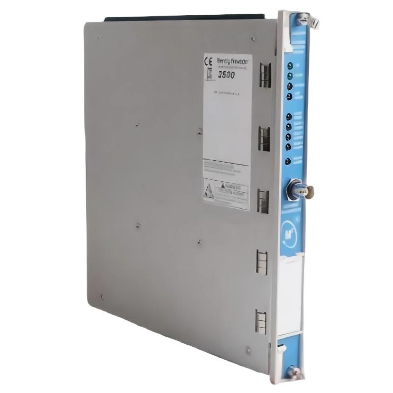
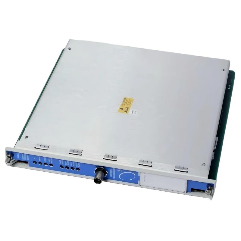
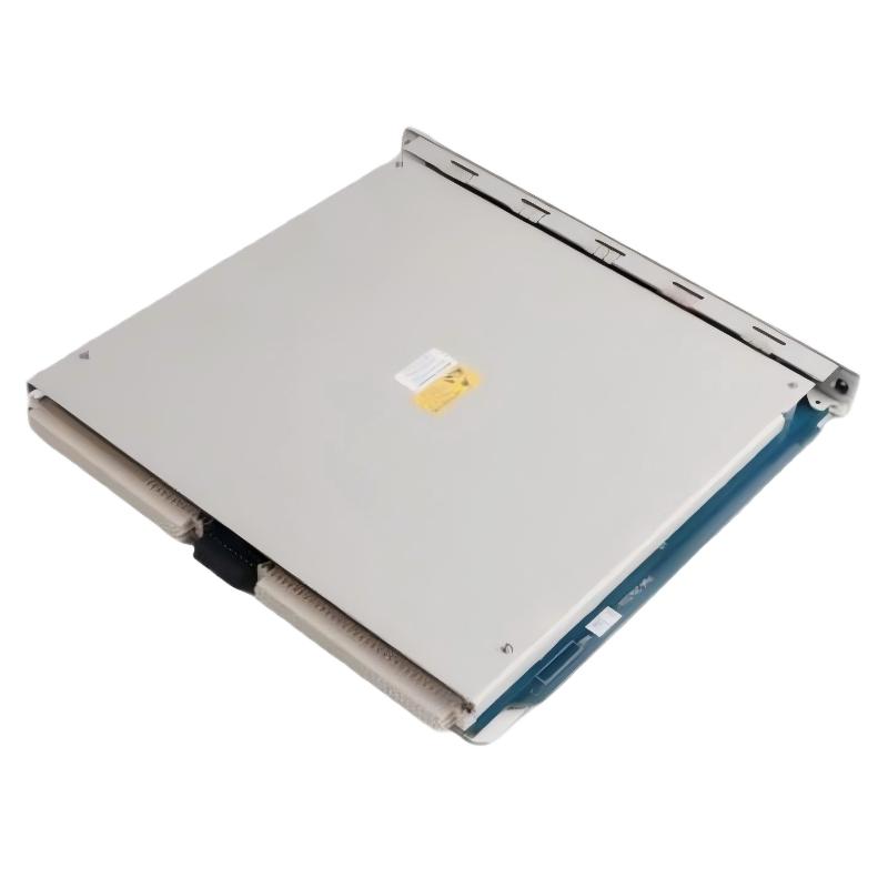
- Bently Nevada
- 3500/53-02-00 286566-01
- Overspeed Detection Module
- USA
- 241.3 × 24.4 × 241.8 mm
- 0.92kg
- Xiamen, China
- New & In Stock
- T/T, PayPal, Western Union
- 1 Year
- 1-3 Working Days
- DHL, UPS, TNT, FedEx and EMS.
- 24-Hour Service
- COO
- 2
Our advantage

Global Logistics
We have a 10-year logistics and express cooperation agreement, so our products can be shipped to any place in the world.

Brand new and original
Our products are imported in bulk from the place of origin. Because of the cooperative relationship, our products are all original and 100% new.

24-hour service
We provide 7*24 hours service to our customers. We will be there whenever you need us.

Price advantage
All our products are priced very favorably because we have our own warehouse and supply.
| Company Information | |||
| [email protected] | |||
| Mobile | +8615980777398 | ||
| +8615980777398 | |||
| 15980777398 |
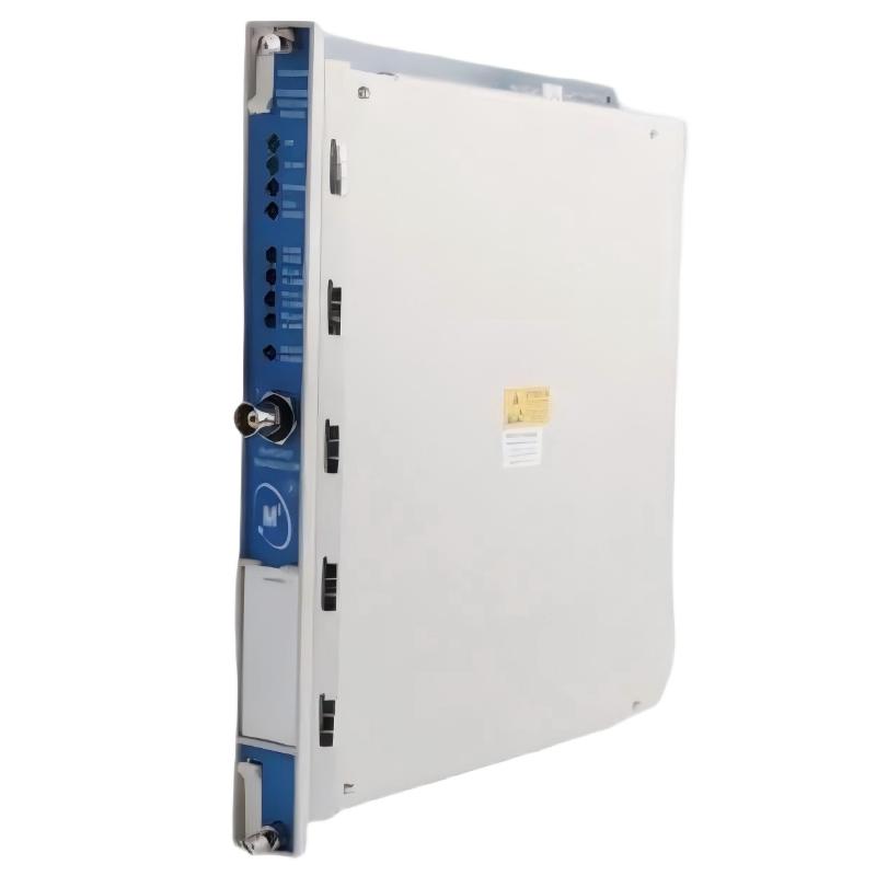
Bently Nevada 3500/53-02-00 — Part Number 286566-01
1. Product Overview
The 3500/53-02-00, part number 286566-01, is an electronic overspeed detection module associated with the 3500 Series machinery protection system. It is designed to monitor rotational speed and detect overspeed conditions in critical rotating machinery.
The module receives speed-related signals from compatible sensors, processes those signals, and evaluates the measured speed against configured protection limits. When the applicable trip criteria are met, it provides outputs for use in the machine’s overspeed protection arrangement.
Overspeed protection is particularly important for turbines, high-speed compressors, turboexpanders, and other rotating equipment where excessive rotational speed can create substantial mechanical stress. A dedicated protection function helps detect an abnormal speed condition so that the designated shutdown system can respond.
The 3500/53 is intended to operate as part of a compatible rack-based protection system. It is not a standalone sensor and should not be treated as an independent shutdown system without the necessary sensors, power supplies, configuration, output circuits, and final trip devices.
Important model-number distinction: The part number 286566-01 is associated with the 3500/53M overspeed detection module in product listings. The 3500/53-02-00 designation and 286566-01 should be checked together against the installed module’s label and approved equipment records before ordering a replacement.
2. Brand and Product Classification
| Parameter | Specification |
|---|---|
| Brand | Bently Nevada |
| Model designation | 3500/53-02-00 |
| Part number | 286566-01 |
| Product name | Electronic Overspeed Detection Module |
| Product family | 3500 Series |
| Product category | Machinery speed monitoring and overspeed protection |
| Primary function | Detects excessive rotational speed from compatible sensor signals |
| Typical installation | Compatible 3500 rack |
| Input signal sources | Compatible proximity transducers or magnetic pickups |
| Protection function | Speed monitoring and configured overspeed trip detection |
| Output functions | Recorder output and relay outputs, according to configuration |
| Redundancy | Supported multi-module voting arrangements, subject to system design |
| Power supply | Supplied through the compatible rack |
| Main card dimensions | Approximately 241.3 × 24.4 × 241.8 mm |
| Main card weight | Approximately 0.82–0.92 kg, depending on the documented version |
| I/O module dimensions | Approximately 241.3 × 24.4 × 99.1 mm |
| I/O module weight | Approximately 0.45 kg |
| Shipping weight | Depends on packaging and supplied accessories |
| Package dimensions | Supplier-dependent; not the same as module dimensions |
The main card and its associated rear I/O module are separate components. Their dimensions and weights should therefore be recorded separately rather than combined into a single figure without confirming what the supplied assembly includes.
3. Detailed Technical Parameters
The following specifications summarize the commonly listed characteristics of the 3500/53M overspeed detection module and its associated I/O assembly.
| Parameter | Technical specification |
|---|---|
| Model | 3500/53-02-00 |
| Part number | 286566-01 |
| Module type | Electronic overspeed detection module |
| Product series | 3500 Series |
| Input signal type | Speed pulse signal from a compatible proximity transducer or magnetic pickup |
| Input signal range | +10.0 V to −24.0 V DC, internally limited |
| Input impedance | 20 kΩ |
| Maximum input frequency | Up to 20 kHz for supported configurations |
| Speed range | Up to 99,999 RPM, depending on configuration |
| Pulses per revolution | Configurable according to the sensor and system setup |
| Typical power consumption | 8.0 W |
| Transducer power supply | −24 V DC, up to 40 mA maximum, where supported |
| Recorder output | 4–20 mA, proportional to configured full-scale speed |
| Output impedance | Approximately 550 Ω |
| Current-output load resistance | 0–600 Ω |
| Output voltage compliance | 0 to +12 V DC across the load |
| Recorder output resolution | Approximately 0.3662 µA per bit |
| Recorder output update rate | Approximately 100 ms |
| Relay type | SPDT, single-pole double-throw |
| Operating temperature | −30°C to +65°C |
| Storage temperature | −40°C to +85°C |
| Relative humidity | Up to 95%, non-condensing |
| Main card dimensions (H × W × D) | 241.3 × 24.4 × 241.8 mm |
| Main card weight | Approximately 0.82–0.92 kg, depending on the version |
| I/O module dimensions (H × W × D) | 241.3 × 24.4 × 99.1 mm |
| I/O module weight | Approximately 0.45 kg |
| Rack space | One full-height front slot for the main module and one full-height rear slot for the corresponding I/O module |
| Package dimensions | Not fixed; depend on packaging |
| Gross shipping weight | Not confirmed for the exact supplied assembly |
The specifications above are reference values for the module family, not a substitute for the applicable revision-specific manual. The precise speed range, accuracy, input configuration, relay logic, and output behavior must be confirmed for the installed hardware and approved configuration.
4. Model Number and Part Number Explanation
The model designation and hardware part number identify related aspects of the product.
| Identifier | Description |
|---|---|
| 3500 | Machinery monitoring and protection system family |
| /53 | Electronic overspeed detection module |
| -02 | Configuration option associated with the specified model |
| -00 | Approval option indicated by the ordering code |
| 286566-01 | Main module hardware part number |
| Associated I/O assembly | Must be identified from the installed rear I/O module label |
The full part number is important when purchasing a replacement. Modules with similar model names may have different hardware revisions, I/O configurations, approval options, or system requirements.
For the requested combination, verify the front-panel label, rear I/O part number, and rack documentation before placing an order. The part number 286566-01 is also associated with the 3500/53M designation in product listings, so it is worth confirming the exact model printed on the existing unit.
5. Product Introduction
The 3500/53 overspeed detection module is designed to monitor rotational speed and provide a dedicated overspeed protection function for critical machinery.
During operation, a compatible sensor generates pulses as a shaft or another rotating target moves. The module receives the signal, determines the corresponding rotational speed, and compares the measured value with the configured protection limits.
If the measured speed reaches the applicable trip threshold, the module’s configured output can be used to initiate a protective response through the associated relay and shutdown circuitry.
This arrangement is particularly valuable for machines that operate at high speed or have strict maximum-speed limits. Excessive speed can generate forces that increase rapidly with rotational speed, placing considerable stress on rotors, blades, couplings, bearings, and other mechanical components.
The module forms part of a larger protection system. Correct operation depends not only on the module itself but also on the sensor type, pulse quality, sensor placement, configuration settings, power supplies, rack compatibility, and final trip circuit.
For critical applications, multiple modules can be arranged in supported voting architectures. Common arrangements include two-out-of-two and two-out-of-three voting, subject to the particular system design. These arrangements must be engineered and tested as a complete protection system rather than treated as a simple module-counting exercise.
6. Product Applications
6.1 Steam turbines
Steam turbines are commonly used in power generation and industrial drive applications. Their protection systems need to detect excessive rotational speed and initiate the designated response when a configured limit is exceeded.
The 3500/53 can form part of a compatible overspeed protection arrangement by processing speed signals from suitable sensors. Correct selection requires confirmation of the turbine’s operating range, trip thresholds, sensor arrangement, and shutdown interface.
6.2 Gas turbines
Gas turbines operate at high rotational speeds and may be used in power plants, mechanical drive systems, and industrial facilities.
An overspeed detection module can monitor the speed signal and provide a dedicated protection output when the configured criteria are met. The module must be integrated with the machine’s approved protection architecture and tested under the applicable commissioning procedures.
6.3 Centrifugal compressors
Centrifugal compressors are widely used in refineries, gas processing plants, petrochemical facilities, and other continuous-process installations.
The 3500/53 may be used as part of an overspeed protection arrangement where the compressor’s speed signal and system requirements are compatible with the module. Its role is to support speed protection, not to replace the compressor’s complete vibration, temperature, pressure, and process-control systems.
6.4 Turboexpanders
Turboexpanders can operate at very high speeds in gas processing, refrigeration, and energy-recovery applications.
A dedicated overspeed detection function helps identify a speed excursion that may require protective action. The module’s suitability depends on the required speed range, sensor configuration, response requirements, and trip-system design.
6.5 Generator drive systems
In turbine-generator installations, rotational speed is an important operating parameter. Overspeed protection can help protect the rotating equipment if the machine exceeds its permitted speed range.
The 3500/53 can contribute to this protection function when used in a suitable configuration. It does not replace generator electrical protection, turbine control, or other required machinery protection functions.
6.6 High-speed industrial rotating equipment
Specialized rotating machines may require dedicated speed monitoring because excessive speed can create severe mechanical loads.
The module may be considered where the required sensor input, speed range, and protection architecture match the installed system. The engineering design should define the trip threshold, expected response, alarm behavior, reset procedure, and testing requirements.
7. Product Advantages
7.1 Dedicated overspeed protection
The module is designed for overspeed detection rather than only general vibration trending. This allows the speed-protection function to be treated as a distinct part of the machine’s protection strategy.
7.2 Compatibility with suitable speed sensors
The module family supports compatible proximity transducers and magnetic pickups. This provides flexibility when designing a sensing arrangement for different types of rotating machinery.
The sensor must still be selected according to the required signal characteristics, operating speed, target geometry, and installation environment.
7.3 Support for redundant voting architectures
Supported multi-module configurations can be used to build voting arrangements for critical protection applications.
A properly engineered redundant system can improve availability and help manage certain module or signal faults. The overall result depends on sensor independence, power architecture, wiring, module configuration, and the final trip circuit.
7.4 Integration into a rack-based protection system
The 3500 architecture provides a modular rack arrangement for compatible monitoring and protection equipment.
This can simplify the organization of system components and provide a common framework for monitoring, communication, and protection functions.
7.5 Configurable speed thresholds
The protection settings can be configured to match the requirements of the particular machine and operating range.
Correct configuration is essential. Incorrect speed scaling, trip thresholds, or relay logic can prevent the system from responding as intended.
7.6 Recorder and relay interfaces
The module family supports a recorder output and relay-based interfaces, subject to the installed configuration. These outputs can provide speed-related information to compatible systems and support the configured protection logic.
The output’s intended load, signal scaling, and trip behavior should be checked during commissioning.
7.7 Front-panel status indication
Status indicators can help maintenance personnel identify basic operating conditions, communication status, bypass or test states, and alarm conditions where supported.
These indicators are useful for initial troubleshooting but do not replace full system diagnostics or functional proof testing.
7.8 Maintainable modular hardware
A modular rack-based design can simplify replacement and maintenance when the replacement module, I/O assembly, and system configuration are compatible.
Recording the full model and part numbers helps reduce the risk of installing a module that looks similar but has a different configuration.
8. Installation and Commissioning Considerations
Before installing or replacing the module, check the following items.
– Confirm the part number. Verify the front-panel model, main card number, rear I/O number, and hardware revision.
– Check rack compatibility. Confirm that the rack and power supplies support the required module configuration.
– Verify sensor compatibility. Ensure that the proximity transducer or magnetic pickup provides a suitable signal for the module.
– Validate speed scaling. Check the number of pulses per revolution, sensor arrangement, and configured speed range.
– Review trip thresholds. Ensure that the protection settings match the approved machinery protection design.
– Check relay logic. Confirm how the module output interacts with the external shutdown circuit.
– Validate redundant configurations. For voting arrangements, check the module count, signal paths, power supplies, voting logic, and fault response.
– Perform functional testing. Follow the approved commissioning procedure to test signal detection, speed calculation, alarm behavior, trip output, and reset operation.
– Document all changes. Record the installed part numbers, settings, test results, and any approved configuration changes.
Because overspeed protection is a critical machinery function, installation and testing should be performed by qualified personnel under the site’s approved procedures.
9. Five Related Models in the Same Series
The following models are related to the 3500 rack-based machinery monitoring and protection system. They perform different functions and should not be treated as direct substitutes for the overspeed detection module.
| Model | Product description | Main parameters | Dimensions (H × W × D) | Weight (kg) |
|---|---|---|---|---|
| 3500/15 | Rack power supply module | Provides rack power; exact configuration depends on the selected power-supply version | Version-dependent; confirm the applicable drawing | Not confirmed |
| 3500/22M | Transient Data Interface | Supports rack communication and data-interface functions | Full-height rack module; verify exact hardware dimensions | Not confirmed |
| 3500/25 | Keyphasor module | Processes compatible phase-reference signals for rotational timing | Full-height rack module; verify exact hardware dimensions | Not confirmed |
| 3500/40M | Proximitor monitor | Monitors compatible proximity-probe signals for shaft-related measurements | Approximately 241.3 × 24.4 × 241.8 mm for the full-height module format | Approximately 0.91 |
| 3500/42M | Proximitor/Seismic monitor | Supports compatible vibration and displacement monitoring channels | Approximately 241.3 × 24.4 × 241.8 mm for the full-height module format | Approximately 0.91 |
The dimensions and weights of rack modules vary by hardware version and configuration. The values above are indicative for the full-height monitor-module format; exact figures should be confirmed for the selected part number.
10. Five Other Popular Models from the Same Brand
The following products cover common sensing and machinery-monitoring functions. Their purposes differ from the 3500/53 overspeed detection module.
| Model | Product description | Main parameters | Dimensions | Weight (kg) |
|---|---|---|---|---|
| 330101 | 3300 XL proximity probe family | Non-contact displacement measurement; thread, probe length, and cable options depend on the full model | Depends on the selected probe configuration | Not confirmed |
| 330103 | 3300 XL proximity probe family | Compatible probe family for shaft displacement and vibration measurements | Depends on probe length and mounting options | Not confirmed |
| 330180 | 3300 XL 8 mm proximity probe family | Non-contact measurement of relative shaft movement and vibration | Depends on the selected probe length and mounting configuration | Not confirmed |
| 330930 | 3300 XL NSv extension cable family | Extension cable available in different lengths and construction options | Depends on the selected cable length | Depends on length and construction |
| 3500/42M | Proximitor/Seismic monitor | Rack-based monitoring of compatible proximity and seismic inputs | Approximately 241.3 × 24.4 × 241.8 mm for the full-height module format | Approximately 0.91 |
The 3300 XL products are primarily sensing-system components, while the 3500/42M is a rack-based monitoring module. They can form part of a broader machinery monitoring installation when the equipment is compatible, but they do not replace the dedicated overspeed protection function of the 3500/53.
11. Product Selection and Comparison Guide
| Selection factor | 3500/53-02-00, 286566-01 | What to verify |
|---|---|---|
| Main function | Electronic overspeed detection | Confirm that a dedicated overspeed protection function is required |
| Input signal | Compatible speed-sensor signal | Verify sensor type and electrical compatibility |
| Input impedance | 20 kΩ | Check the selected sensor’s output requirements |
| Input signal range | +10.0 V to −24.0 V DC, internally limited | Confirm signal amplitude and polarity |
| Typical power consumption | 8.0 W | Check rack power capacity |
| Recorder output | 4–20 mA | Confirm output scaling and load |
| Relay output | SPDT | Verify the required trip interface |
| Redundancy | Supported multi-module voting arrangements | Confirm the complete protection architecture |
| Operating temperature | −30°C to +65°C | Check the actual installation temperature |
| Main card dimensions | Approximately 241.3 × 24.4 × 241.8 mm | Confirm the hardware drawing |
| Main card weight | Approximately 0.82–0.92 kg | Confirm the exact revision |
| I/O module weight | Approximately 0.45 kg | Confirm the rear I/O part number |
| Shipping weight | Depends on packaging | Request the actual gross weight |
| System compatibility | 3500 rack-based protection system | Verify rack, firmware, module, and I/O compatibility |
12. Maintenance and Lifecycle Management
Regular maintenance is important because an overspeed protection system may remain inactive during normal operation but be required to respond rapidly during an abnormal event.
During scheduled maintenance, inspect the module and rack connections for visible damage, loose seating, contamination, or abnormal status indications. Review event records and system diagnostics according to the site’s maintenance procedure.
Functional proof testing should verify the complete protection path, including sensor signal detection, speed calculation, configured trip thresholds, relay operation, and the final shutdown interface. Testing should be planned so that it does not create an unintended trip or compromise safe machinery operation.
When replacing a module, verify the main card part number, associated I/O assembly, hardware revision, rack compatibility, and configured settings. After installation, carry out the required functional tests and document the results before returning the protection function to service.
If speed readings are unstable or trip behavior is inconsistent, investigate the entire signal and protection path. Potential causes include sensor faults, wiring problems, incorrect scaling, module configuration, rack power, relay circuitry, or external shutdown logic. Replacing the module alone may not resolve a problem originating elsewhere.
Spare-parts planning should include the exact hardware identifiers, compatible I/O assemblies, configuration records, proof-test requirements, and supplier confirmation of the delivered revision.
13. Final Product Summary
The Bently Nevada 3500/53-02-00, part number 286566-01, is associated with the 3500 Series electronic overspeed detection system. Its purpose is to process compatible rotational-speed signals and provide outputs for a configured overspeed protection arrangement.
Its key characteristics include compatible proximity-probe or magnetic-pickup inputs, a nominal 20 kΩ input impedance, typical power consumption of 8.0 W, recorder and relay interfaces, and support for appropriately engineered redundant voting configurations.
The most important factors when selecting this module are the exact hardware identity, sensor compatibility, rack configuration, speed range, trip logic, and associated I/O assembly.
For procurement and engineering records, confirm the complete part number and revision, the main card and I/O dimensions, and the net weight of the actual supplied assembly. This avoids confusing main-card measurements with the combined assembly or shipping package.