

ProductPRODUCT
Featured products
Contact Us
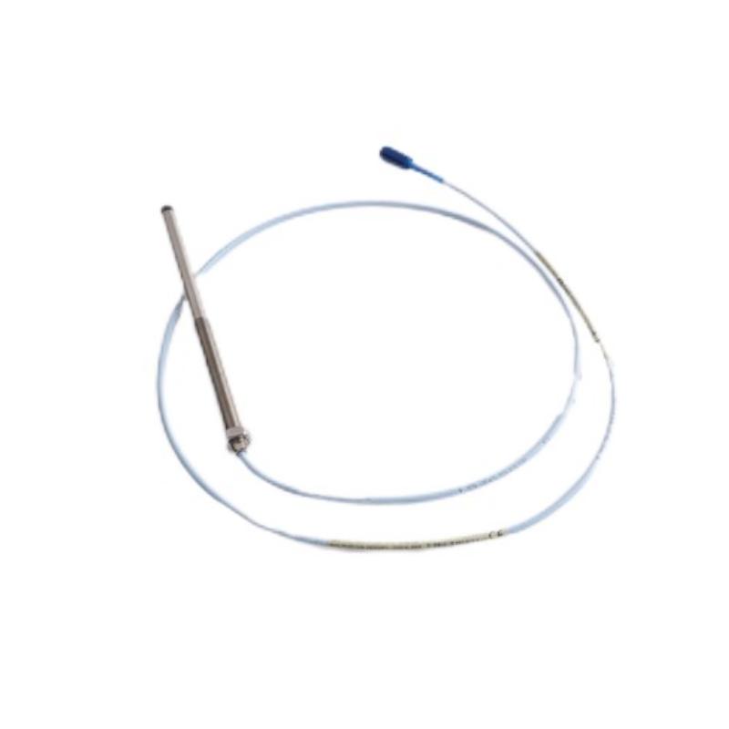
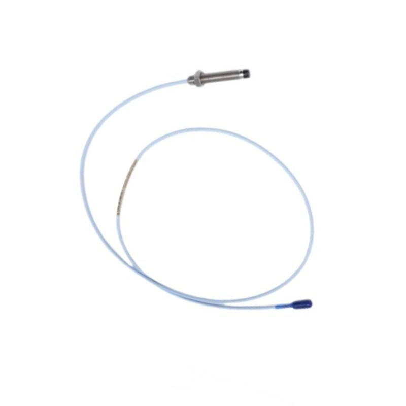
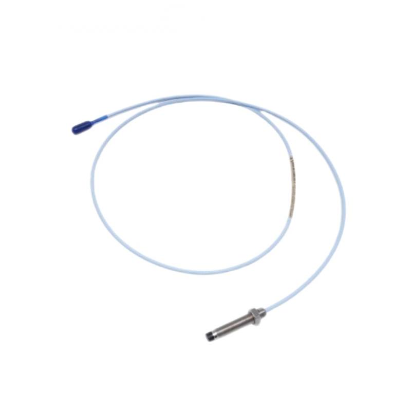
- Bently Nevada
- 330910-00-10-05-02-CN
- 3300 NSv Proximity Probe
- USA
- 100 mm
- 0.15kg
- Xiamen, China
- New & In Stock
- T/T, PayPal, Western Union
- 1 Year
- 1-3 Working Days
- DHL, UPS, TNT, FedEx and EMS.
- 24-Hour Service
- COO
- 2
Our advantage

Global Logistics
We have a 10-year logistics and express cooperation agreement, so our products can be shipped to any place in the world.

Brand new and original
Our products are imported in bulk from the place of origin. Because of the cooperative relationship, our products are all original and 100% new.

24-hour service
We provide 7*24 hours service to our customers. We will be there whenever you need us.

Price advantage
All our products are priced very favorably because we have our own warehouse and supply.
| Company Information | |||
| [email protected] | |||
| Mobile | +8615980777398 | ||
| +8615980777398 | |||
| 15980777398 |
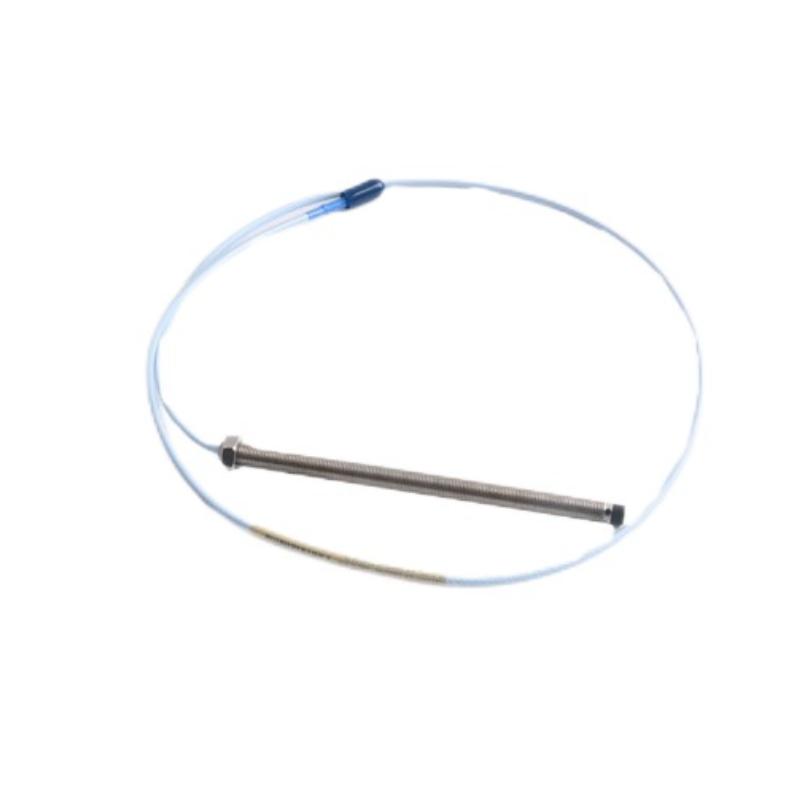
Bently Nevada 330910-00-10-05-02-CN Proximity Probe: Technical Specifications, Product Description, Applications, and Model Recommendations
1. Product Overview
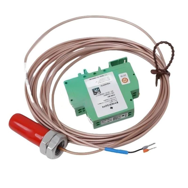
The Bently Nevada 330910-00-10-05-02-CN is a 3300 NSv proximity probe designed for non-contact measurement of shaft movement in rotating machinery. It is used in compatible machinery monitoring systems to provide displacement-related signals for equipment condition monitoring and protection.
The probe features an M10 × 1 metric mounting thread and an armored construction. Its specified configuration includes a zero-millimetre unthreaded length, a 100 mm overall case length, a 0.5 m total probe length, and a miniature coaxial ClickLoc connector with standard cable.
The 3300 NSv series is designed for applications where a compact sensing arrangement is needed, including installations with limited space around the monitored shaft. The probe operates as part of a complete measurement channel and must be paired with compatible driver electronics, cabling, and monitoring equipment.
2. Technical Parameters
| Parameter | Specification |
|---|---|
| Product model | 330910-00-10-05-02-CN |
| Brand | Bently Nevada |
| Product series | 3300 NSv |
| Product type | Eddy-current proximity probe |
| Primary function | Non-contact shaft displacement measurement |
| Mounting thread | M10 × 1 |
| Probe construction | Armored |
| Unthreaded length | 0 mm |
| Overall case length | 100 mm |
| Total probe length | 0.5 m (500 mm / approximately 19.7 in) |
| Connector type | Miniature coaxial ClickLoc |
| Cable type | Standard cable |
| Cable impedance | 75 Ω coaxial cable |
| Probe-tip material | Polyphenylene sulfide (PPS), subject to configuration verification |
| Probe case material | AISI 304 stainless steel, subject to configuration verification |
| Measurement principle | Eddy-current sensing |
| Nominal linear range | Approximately 1.5 mm (60 mils) for the applicable matched system |
| Typical recommended gap | Approximately 1.0 mm (40 mils), subject to the system installation procedure |
| Typical scale factor | Approximately 7.87 V/mm (200 mV/mil) for the applicable matched system |
| Frequency response | Typically 0–10 kHz, subject to the matched system specifications |
| Approval suffix | CN; confirm the specific country approval and certification requirements for the supplied unit |
| Dimensions | 100 mm case length, M10 × 1 thread, 500 mm total probe length; the exact overall assembly envelope should be checked against the dimensional drawing |
| Weight | Approximately 0.15 kg (150 g), listed product weight; confirm net weight and packaging weight with the supplier |
| Typical installation | Fixed mounting at a designated machinery measurement point |
| Compatible equipment | Matching 3300 NSv driver, suitable extension components if required, and compatible monitoring electronics |
| Intended environment | Industrial rotating machinery, within the specified operating and installation limits |
Technical note: The 100 mm case length and 0.5 m total length describe different parts of the assembly. The total length should not be interpreted as the threaded metal body length. The approximately 0.15 kg figure is a commercial listing value, not a guaranteed shipping or net weight for every supplied package. Measurement performance must be verified against the correct matched system documentation.
3. Model Number Breakdown
The complete model number identifies the mechanical configuration, cable length, connector arrangement, and approval option. Each section should be checked when ordering a replacement.
| Model section | Meaning | Configuration |
|---|---|---|
| 330910 | Base model | 3300 NSv proximity probe, M10 × 1 thread, armored construction |
| 00 | Unthreaded-length option | 0 mm |
| 10 | Overall case-length option | 100 mm |
| 05 | Total-length option | 0.5 m |
| 02 | Connector and cable option | Miniature coaxial ClickLoc connector, standard cable |
| CN | Country-specific option | Confirm the applicable country-specific approval and documentation requirements |
The model code should be treated as a complete configuration identifier rather than a general product-family name. A probe with a different case length, cable length, connector, or approval suffix may not be a direct replacement, even when its base model is also 330910.
4. Product Introduction
4.1 Non-contact sensing technology
The 330910 proximity probe uses the eddy-current measurement principle. It produces an electromagnetic field at the sensing tip and detects changes in the electrical response as the distance to a suitable conductive target changes.
When the monitored shaft moves relative to the stationary probe, the gap changes. The compatible driver electronics convert the probe’s response into a measurement signal that can be used by a machinery monitoring system.
Because the probe is designed for non-contact operation, it does not need to touch the rotating shaft during normal measurement. This makes the technology suitable for continuous monitoring of shaft movement in appropriately designed installations.
4.2 M10 × 1 mounting configuration
The M10 × 1 thread provides a metric mounting arrangement for equipment designed to accept this probe format. Correct thread matching is important for secure installation and accurate positioning.
The 100 mm overall case length allows the probe to be positioned according to the mechanical requirements of the measurement point. The actual installation depth depends on the mounting arrangement, the unthreaded length, the required probe gap, and the available clearance around the machine.
4.3 Armored construction
The armored configuration provides additional mechanical protection around the cable section. This can be beneficial in industrial environments where installation handling, nearby components, or routine maintenance may expose the cable to incidental mechanical contact.
Armor should not be regarded as complete protection against all forms of damage. The cable still needs suitable routing, strain relief, bend-radius control, and protection from excessive pulling forces or harsh environmental conditions.
4.4 Compact 3300 NSv sensing design
The 3300 NSv family is intended for proximity measurement applications that benefit from a relatively compact probe arrangement. The probe can be used where installation geometry, shaft dimensions, or restricted mounting clearance make the choice of sensing hardware particularly important.
The correct probe must still be selected according to the shaft material, target geometry, measurement range, and requirements of the associated driver electronics.
4.5 Part of a complete measurement channel
The 330910 is a sensing component, not a stand-alone machinery protection system. Its measurements depend on a compatible system that may include:
-
The proximity probe.
-
Compatible driver or Proximitor electronics.
-
Extension cable or other matching interconnection components, where required.
-
Machinery monitoring equipment.
-
Suitable mounting hardware and installation provisions.
A correctly matched measurement channel can provide useful shaft-related data for monitoring and maintenance decisions.
5. Product Applications
5.1 Steam and gas turbines
Turbines contain rotating assemblies that may require continuous measurement of shaft movement and vibration. A correctly configured proximity probe can provide shaft-displacement signals to a compatible monitoring system.
These measurements can help operating personnel observe changes during startup, normal operation, load changes, and shutdown. The suitability of the probe depends on the turbine’s measurement design and the required system performance.
5.2 Industrial compressors
Compressors are often important to the stability of continuous industrial processes. Shaft movement and vibration can change with operating load, speed, alignment, and mechanical condition.
A 3300 NSv proximity probe can be used at suitable measurement points to provide displacement-related signals. Monitoring personnel can evaluate these readings alongside operating data and historical trends to identify conditions requiring further investigation.
5.3 Pumps and pumping systems
Industrial pumps may operate in power plants, water-treatment facilities, chemical plants, and process industries. On suitable machines, proximity measurements can support monitoring of shaft movement and vibration.
The probe should be chosen according to the pump’s mounting arrangement, shaft target, operating environment, and monitoring-system requirements. Not every pump installation requires a proximity probe.
5.4 Electric motors
For appropriate motor installations, proximity probes can provide information about shaft movement relative to a fixed reference point.
The readings may be evaluated together with bearing temperatures, operating speed, electrical load, and other condition indicators. This can help maintenance personnel distinguish normal changes in operating behavior from changes that warrant closer inspection.
5.5 Gearboxes and rotating transmission equipment
Gearboxes, couplings, and other rotating equipment may require shaft-related measurements at designated locations. A proximity probe can support these applications when the target material, shaft geometry, and monitoring architecture are suitable.
Probe placement is important because the measured movement depends on the relative position of the probe and the conductive target.
5.6 Power generation equipment
Power generation facilities commonly monitor critical rotating assets to support operational reliability and maintenance planning. Proximity probes can form part of the measurement channels used on compatible turbines, compressors, and other rotating machinery.
The exact application and required alarm settings should be established by the equipment design and monitoring-system requirements.
5.7 Oil, gas, and process industries
Process plants often operate equipment continuously and may face significant costs when critical machinery fails unexpectedly. A properly installed proximity probe can supply shaft-related measurements for use in a broader condition-monitoring strategy.
Its armored cable arrangement may be useful where additional mechanical protection is needed, although environmental suitability must be confirmed for each installation.
5.8 Predictive and preventive maintenance
The probe can contribute to maintenance programs by providing repeated measurements that can be compared over time. A change in shaft-displacement readings may prompt further investigation, particularly when it coincides with other abnormal indicators.
The probe does not independently identify every fault. Reliable diagnosis depends on measurement quality, monitoring-system configuration, machine operating conditions, and appropriate interpretation of the data.
6. Product Advantages
6.1 Non-contact measurement
The sensing principle allows shaft movement to be measured without direct physical contact between the probe tip and the rotating target.
This avoids normal sensor-to-shaft rubbing and makes the technology suitable for continuous measurement when correctly installed.
6.2 Metric mounting thread
The M10 × 1 threaded body provides a defined mounting interface for compatible metric installations.
Matching the thread and installation geometry helps simplify replacement work and reduces the risk of using a probe that cannot be mounted correctly.
6.3 Armored cable protection
The armored construction offers additional mechanical protection around the cable section compared with an unarmored arrangement.
This can be useful in machinery areas where cables may be exposed to incidental contact during installation or maintenance.
6.4 Defined 100 mm case length
The 100 mm case-length configuration gives the installer a specific mechanical dimension to work with when checking probe placement and available clearance.
Confirming this dimension before ordering is especially important when replacing an existing probe in a fixed mounting location.
6.5 Short integral cable configuration
The 0.5 m total-length option can be useful where the connection arrangement requires a shorter probe cable. The overall system cable length must still meet the requirements of the selected driver and monitoring equipment.
A shorter cable should not be substituted for a longer configuration without checking the complete transducer-system requirements.
6.6 Standard ClickLoc connector
The miniature coaxial ClickLoc connector provides a defined connection interface for compatible components.
The connector type must match the installed cable and associated electronics. Physical fit alone is not sufficient to establish electrical compatibility.
6.7 Supports continuous condition monitoring
When connected to suitable monitoring electronics, the probe can provide ongoing measurements rather than relying only on periodic manual inspections.
This information can help maintenance teams observe trends and decide when additional checks are needed.
6.8 Suitable for integration into existing systems
For installations already designed around the 3300 NSv family, a correctly specified replacement probe may allow the existing monitoring arrangement to be maintained.
Before replacement, the complete model number, cable arrangement, driver compatibility, and approval requirements should be checked.
6.9 Helps support equipment reliability
A reliable measurement channel can provide useful information about shaft behavior. This can support machinery-condition assessment, maintenance planning, and decisions about whether abnormal readings require further investigation.
The benefit depends on correct installation, suitable monitoring thresholds, and consistent interpretation of the measurements.
7. Installation and Maintenance Recommendations
1. Confirm the full part number. Check that the installed probe and replacement have matching configuration codes.
2. Verify the mounting interface. Confirm the M10 × 1 thread and the required mounting depth.
3. Check the case length. Ensure the 100 mm case is compatible with the available mounting space and the intended measurement point.
4. Confirm the required probe gap. Set the gap according to the applicable driver and monitoring-system instructions.
5. Inspect the shaft target. The target must be suitable for eddy-current measurement and meet the required geometry specifications.
6. Check cable and connector compatibility. Verify the standard cable and miniature coaxial ClickLoc interface against the existing system.
7. Review the approval requirements. Confirm the meaning of the CN suffix for the exact unit and the intended installation location.
8. Protect the cable during installation. Avoid excessive bending, pulling, twisting, and contact with sharp or hot surfaces.
9. Verify the measurement channel. After installation, check signal quality and the required calibration or gap settings before relying on the measurements.
10. Record replacement details. Keep the full part number, installation date, measurement location, and relevant commissioning results with the maintenance records.
8. Five Related Models in the Same Series
The following are related 3300 NSv probe models. The table compares their base configurations and general mechanical characteristics. Complete ordering codes determine the actual length, cable, connector, and approval options.
| Model | Series | Thread and construction | Dimensions | Weight (kg) |
|---|---|---|---|---|
| 330903 | 3300 NSv | M8 × 1, without armor | Case length depends on ordering code | Not confirmed |
| 330904 | 3300 NSv | M8 × 1, with armor | Case length depends on ordering code | Not confirmed |
| 330905 | 3300 NSv | M10 × 1, without armor | Case length depends on ordering code | Not confirmed |
| 330908 | 3300 NSv | 3/8-24 UNF, without armor | Case length depends on ordering code | Not confirmed |
| 330909 | 3300 NSv | 3/8-24 UNF, with armor | Case length depends on ordering code | Not confirmed |
These models are related by product family and intended measurement function, but their mounting threads and cable constructions differ. They should not be treated as direct mechanical replacements without checking the complete specifications.
9. Five Other Popular Models from the Same Brand
The models below represent other commonly encountered proximity-sensing and machinery-monitoring components. Some are probe or cable products, while others belong to the monitoring electronics family.
| Model | Product family | Main function | Dimensions | Weight (kg) |
|---|---|---|---|---|
| 330901 | 3300 NSv | 1/4-28 UNF proximity probe without armor | Depends on the complete configuration | Not confirmed |
| 330902 | 3300 NSv | 1/4-28 UNF proximity probe with armor | Depends on the complete configuration | Not confirmed |
| 330980 | 3300 XL NSv | Proximitor sensor for a compatible NSv transducer system | Depends on mounting option and system configuration | Not confirmed |
| 330100 | 3300 XL | Extension cable family for compatible transducer arrangements | Depends on cable length and connector configuration | Not confirmed |
| 3500/42M | 3500 monitoring system | Machinery monitoring module for supported vibration and position inputs | Rack-module dimensions depend on the specified hardware | Not confirmed |
Selection note: These are related products, not five direct substitutes for the 330910-00-10-05-02-CN. In particular, a Proximitor sensor, extension cable, and monitoring module perform different functions from the probe itself. Compatibility should be checked across the complete measurement channel.
10. Purchasing and Replacement Checklist
| Item to verify | Requirement |
|---|---|
| Complete model number | 330910-00-10-05-02-CN |
| Product series | 3300 NSv |
| Thread | M10 × 1 |
| Probe construction | Armored |
| Unthreaded length | 0 mm |
| Case length | 100 mm |
| Total probe length | 0.5 m |
| Connector | Miniature coaxial ClickLoc |
| Cable | Standard cable |
| Approval option | Confirm country-specific CN requirements |
| Physical dimensions | Check the manufacturer’s dimensional drawing |
| Weight | Approximately 0.15 kg listed; confirm actual net weight |
| Driver compatibility | Verify against the existing NSv transducer system |
| Replacement suitability | Confirm mounting, cable, connector, and system compatibility |
11. Final Product Summary
The Bently Nevada 330910-00-10-05-02-CN is an armored, M10 × 1 threaded proximity probe in the 3300 NSv series. Its specified configuration uses a 100 mm case, a 0.5 m total probe length, and a miniature coaxial ClickLoc connector with standard cable.
Its primary purpose is to measure shaft movement without physical contact and provide a signal to compatible machinery monitoring equipment. Typical applications include suitable turbines, compressors, pumps, motors, and other rotating machinery where shaft displacement or vibration-related measurements are required.
The principal selection considerations are the mounting thread, case length, cable length, connector arrangement, approval suffix, and compatibility with the existing driver and monitoring electronics. Confirming these details before installation or purchasing helps reduce replacement errors and supports dependable operation of the complete measurement channel.