

ProductPRODUCT
Featured products
Contact Us
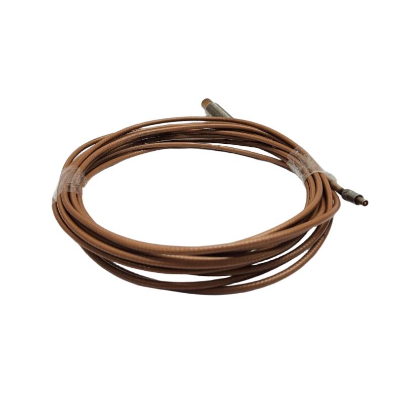
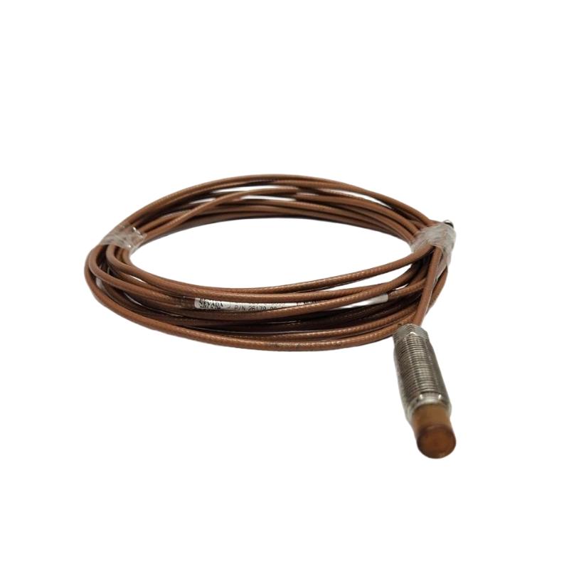
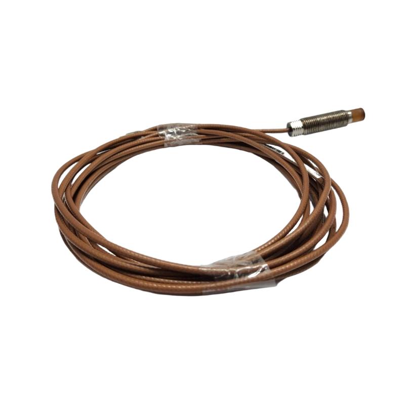
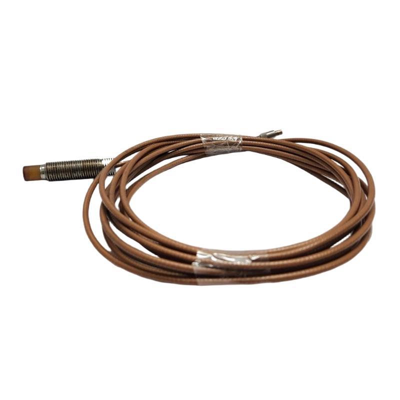
- Bently Nevada
- 26179-01-04-10-02
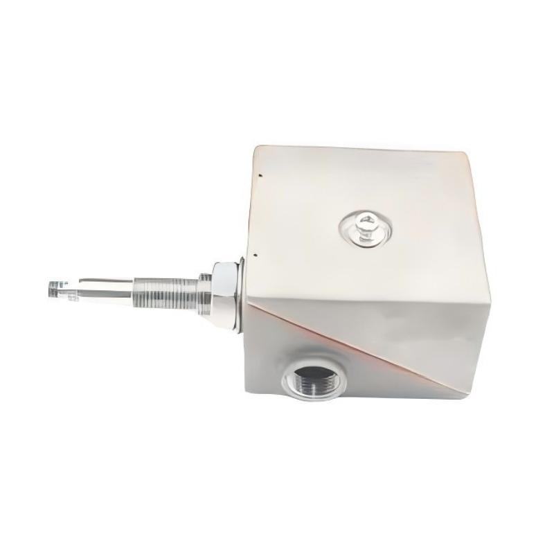
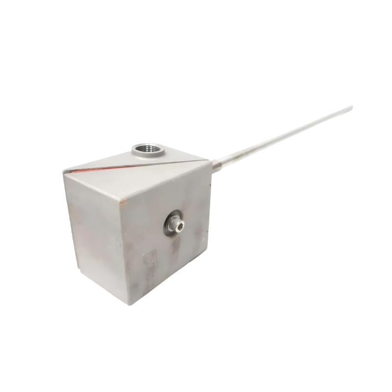
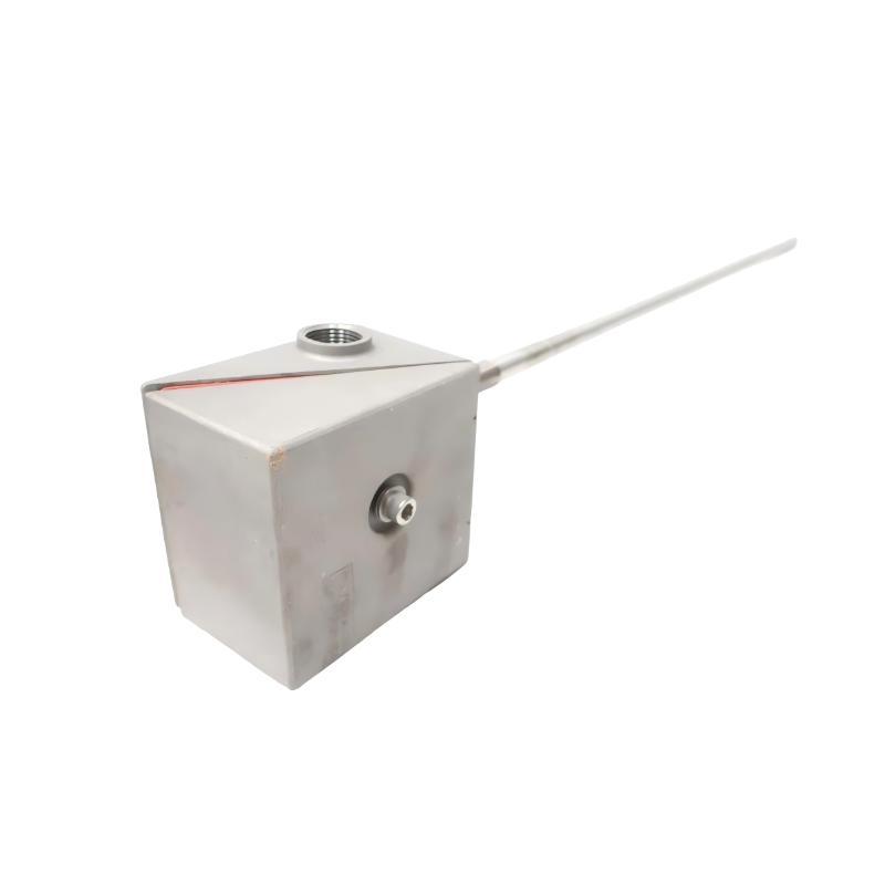
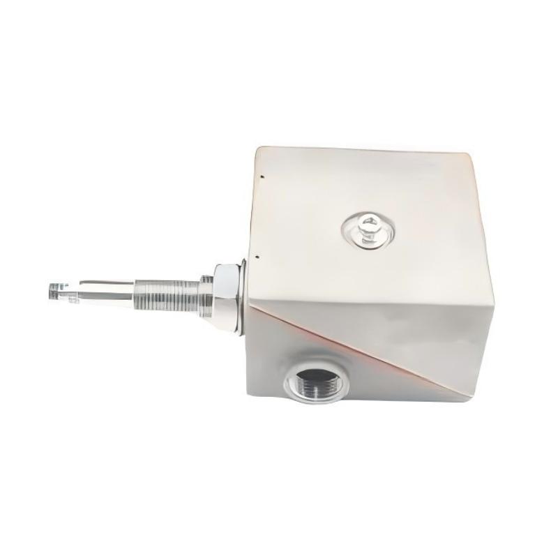
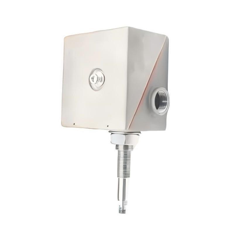
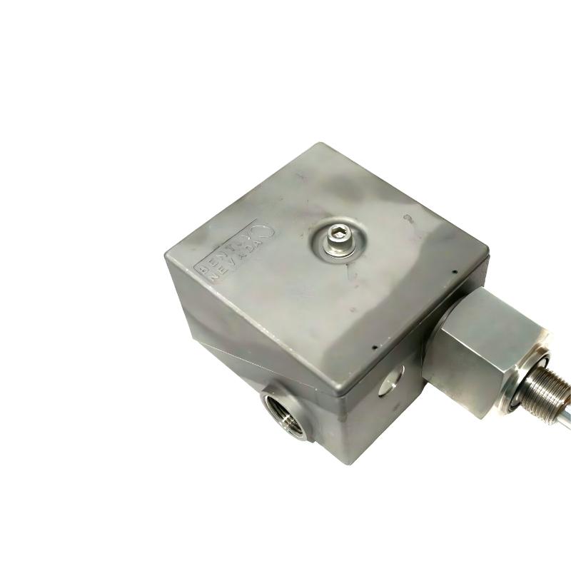
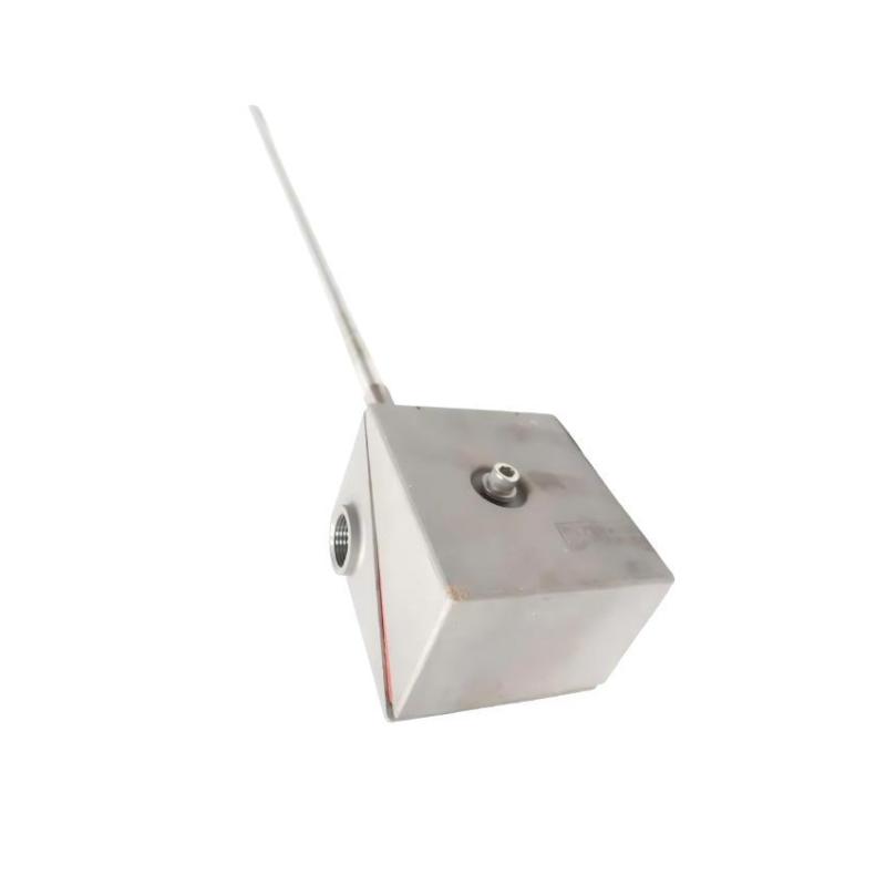
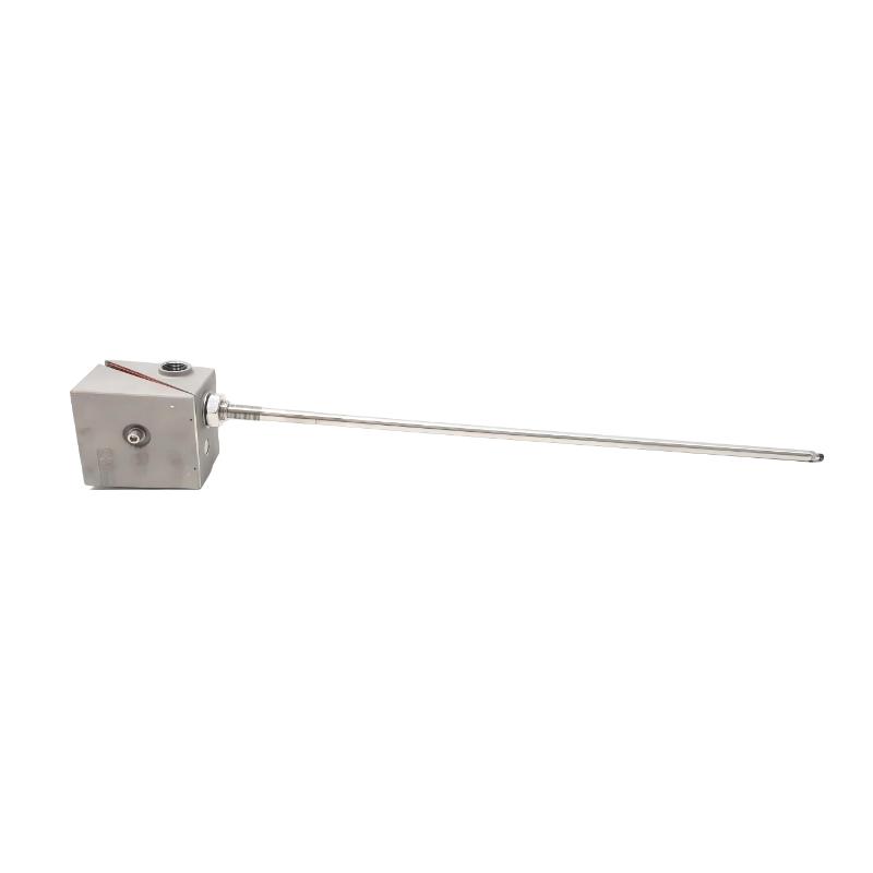
- 7200 11 mm Standard Mount Proximity Probe
- USA
- 1 meter
- 0.59 kg
- Xiamen, China
- New & In Stock
- T/T, PayPal, Western Union
- 1 Year
- 1-3 Working Days
- DHL, UPS, TNT, FedEx and EMS.
- 24-Hour Service
- COO
- 4
Our advantage

Global Logistics
We have a 10-year logistics and express cooperation agreement, so our products can be shipped to any place in the world.

Brand new and original
Our products are imported in bulk from the place of origin. Because of the cooperative relationship, our products are all original and 100% new.

24-hour service
We provide 7*24 hours service to our customers. We will be there whenever you need us.

Price advantage
All our products are priced very favorably because we have our own warehouse and supply.
| Company Information | |||
| [email protected] | |||
| Mobile | +8615980777398 | ||
| +8615980777398 | |||
| 15980777398 |
Product Overview
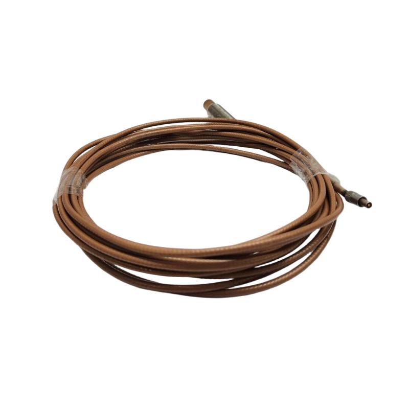
The Bently Nevada 26179-01-04-10-02 is a proximity probe used for non-contact measurement of shaft movement in rotating machinery. It belongs to the 7200 Series and operates as part of an eddy-current transducer system, converting changes in the distance between the probe tip and a conductive target into an electrical signal for compatible monitoring equipment.
In a turbine, compressor, or other high-speed rotating machine, the shaft may move radially as operating conditions change. Such movement can be associated with rotor imbalance, misalignment, bearing condition, or changing mechanical loads. A proximity probe mounted near the shaft detects this movement without physical contact with the rotating component.
The standard-mount arrangement uses a threaded probe body to secure the sensing element at the required measurement point. Correct mounting allows the probe to remain aligned with the shaft and helps prevent unwanted movement caused by vibration or mechanical looseness. The mounting thread, available adjustment, target clearance, and surrounding metalwork all need to be considered during installation.
A typical installation places the probe close to a prepared shaft surface near a bearing or another designated measurement location. As the shaft rotates, the distance between the shaft surface and the probe changes. The resulting electrical signal contains information about shaft vibration and, under suitable measurement conditions, shaft position.
This type of measurement is particularly useful in machinery monitoring systems where shaft displacement is observed continuously. In a compressor train, for example, measurements from probes installed near bearing locations can be evaluated alongside other operating parameters to identify changes in machine behavior. The probe supplies the displacement-related signal, while the connected monitoring equipment performs signal processing and alarm evaluation.
The complete measurement chain matters as much as the sensing element. The probe, integral cable, extension cable, and Proximitor sensor must form a compatible 7200 Series system. Cable length and system configuration affect the electrical characteristics of the measurement circuit, so components from different proximity-probe families should not be substituted solely because their connectors or external appearance seem similar.
For maintenance personnel, the probe is one part of a wider condition-monitoring arrangement. Its measurements can help identify changes in shaft movement, but diagnosing the cause requires consideration of other machine data, operating conditions, and the integrity of the sensing installation.
Technical Specifications
| Parameter | Specification |
|---|---|
| Manufacturer | Bently Nevada |
| Model | 26179-01-04-10-02 |
| Product Type | 7200 Series Standard Mount Proximity Probe |
| Product Series | 7200 Series |
| Sensing Technology | Eddy-current proximity measurement |
| Probe Tip Diameter | 8 mm |
| Mounting Type | Standard mount |
| Thread Type | M10 × 1 |
| Unthreaded Length | 1.0 in |
| Case Length | 1.0 in |
| Target Type | Electrically conductive shaft surface |
| Measurement Principle | Non-contact displacement sensing |
| Typical Measurement Applications | Shaft vibration and shaft position monitoring |
| Total Length | 1 meter |
| System Configuration | Compatible 7200 Series probe, extension cable, and Proximitor sensor |
| Output Processing | Compatible 7200 Series Proximitor and monitoring equipment |
| Mounting Arrangement | Threaded probe body with adjustment and locking hardware |
| Weight | 0.59 kg |
Product Features
- Non-contact measurement: Detects shaft displacement without direct contact with the rotating surface.
- Eddy-current sensing: Converts changes in probe-to-target distance into an electrical measurement signal.
- Standard-mount construction: Uses a threaded body for installation and positioning at a designated measurement point.
- Rotating machinery monitoring: Supports shaft vibration and position measurements when integrated with compatible equipment.
- Continuous signal generation: Allows the connected monitoring system to observe changes in shaft movement over time.
- 7200 Series compatibility: Forms part of a matched proximity transducer system rather than operating as an independent monitoring device.
- Integral cable connection: Connects the probe to the remaining measurement circuit through the specified system arrangement.
- Adjustable installation position: Allows the probe gap to be set during commissioning within the applicable mechanical and electrical limits.
Working Principle
The probe uses eddy-current sensing to measure the distance between its tip and a conductive target, usually a rotating machinery shaft. An alternating electromagnetic field generated by the sensing circuit induces eddy currents in the target. Changes in the probe-to-shaft gap alter the electrical response, allowing the connected Proximitor sensor to produce an output related to displacement.
Rotating Shaft → Eddy-Current Probe → Proximitor Sensor → Monitoring Channel → Vibration or Position Data
When the shaft moves toward or away from the probe, the measured gap changes. The signal-conditioning electronics convert this change into a usable electrical output. A compatible monitoring channel then interprets the signal according to its configured measurement range and calibration.
For shaft vibration monitoring, the dynamic component of the signal represents shaft movement relative to the probe mounting point. The monitoring system can evaluate this movement over time and compare it with configured alarm limits. The probe does not identify the cause of vibration on its own; additional measurements and mechanical investigation may be needed to distinguish imbalance, misalignment, bearing-related movement, or other conditions.
The probe can also contribute to shaft-position measurements when installed and configured for that purpose. Static position and dynamic vibration are different aspects of the signal. Correct interpretation depends on the monitoring channel, installation geometry, and measurement objective.
The initial probe gap must be established during installation. If the probe is positioned outside its specified linear operating region, the output may no longer represent displacement accurately. An incorrect gap can also reduce the available measurement range for shaft movement in one direction.
The probe is part of a complete 7200 Series transducer circuit. The integral cable, any extension cable, and the Proximitor sensor must be selected as a compatible combination. The total electrical cable length is a system-level parameter, not merely a matter of choosing a cable that physically reaches the monitoring cabinet.
Electrical interference, poor shielding practices, loose connections, and an unstable mounting point can affect signal quality. If the measured vibration changes unexpectedly, technicians should examine the complete measurement chain before concluding that the shaft itself has developed a mechanical fault.
Role in a Rotating Machinery Protection System
The Bently Nevada 26179-01-04-10-02 provides the local shaft-displacement measurement used by a compatible machinery monitoring system. Its signal can contribute to vibration monitoring, shaft-position evaluation, and trend analysis when installed at the appropriate machine location.
Shaft Surface → 26179-01-04-10-02 Probe → 7200 Series Proximitor Sensor → Monitoring Channel → Operator Interface
| System Component | Function |
|---|---|
| Bently Nevada 26179-01-04-10-02 | Detects changes in the gap between the probe tip and shaft surface |
| Conductive Shaft Target | Provides the surface against which displacement is measured |
| Probe Mounting Hardware | Holds the probe at the required measurement position |
| Probe Integral Cable | Carries the probe signal within the specified transducer arrangement |
| Compatible Extension Cable | Connects the probe circuit to the Proximitor sensor while maintaining the required system configuration |
| 7200 Series Proximitor Sensor | Conditions the probe signal and produces the corresponding electrical output |
| Machinery Monitoring Channel | Processes the output for shaft vibration or position measurement |
| Monitoring Rack | Collects and evaluates measurement signals from installed sensors |
| Operator Interface | Displays measured values, trends, and configured alarm information |
Industrial Applications
| Application | Typical Use |
|---|---|
| Steam Turbines | Monitoring shaft vibration and relative shaft movement near designated bearing locations |
| Industrial Compressors | Tracking changes in shaft motion during continuous operation |
| Centrifugal Compressor Trains | Supplying proximity measurements to machinery monitoring channels |
| Power Generation Equipment | Supporting rotating machinery condition monitoring |
| Industrial Pumps | Measuring shaft displacement where the machine and monitoring arrangement are compatible |
| Turbomachinery Test Rigs | Collecting shaft movement data during controlled operating tests |
| Bearing Monitoring | Observing relative shaft motion near bearing housings |
| Rotating Equipment Diagnostics | Providing displacement data for vibration analysis |
| Continuous Process Plants | Supporting machinery trend monitoring during changing load conditions |
| Maintenance and Commissioning | Establishing baseline measurements after correct installation and system calibration |
Installation and Maintenance
- Confirm the mounting location: Select a measurement point that provides the required view of the shaft surface and corresponds to the machine’s monitoring arrangement.
- Inspect the target surface: Ensure the shaft surface is suitable for proximity measurement and that its condition is consistent with the system’s measurement requirements.
- Check the mounting thread: Confirm that the mounting provision accepts the specified M10 × 1 threaded probe body and that the mechanical arrangement allows proper adjustment.
- Align the probe with the target: Position the probe so that it measures the intended shaft movement without interference from adjacent structures.
- Set the initial gap: Adjust the probe according to the applicable 7200 Series installation procedure and the requirements of the receiving measurement system.
- Secure the probe body: Tighten the locking hardware as specified, ensuring that the probe cannot move under machine vibration.
- Inspect the integral cable: Check the cable jacket, connector, and termination for damage, contamination, or mechanical strain.
- Match the transducer components: Use a compatible 7200 Series extension cable and Proximitor sensor, maintaining the specified total electrical cable configuration.
- Route the cable carefully: Avoid sharp bends, crushing, excessive tension, and unnecessary proximity to high-interference power wiring.
- Verify the electrical output: Confirm that the Proximitor sensor and monitoring channel produce the expected response for the installed probe and configured gap.
- Establish a baseline reading: Record the measurement under a known machine condition and compare it with the expected operating behavior.
- Review readings during maintenance: Inspect the mounting, connections, cable condition, and measurement trends whenever the monitoring system reports abnormal or unstable values.
If the output becomes noisy or the displayed shaft movement changes unexpectedly, inspect the probe gap, mechanical mounting, cable connections, and system compatibility. A measurement fault should be distinguished from actual shaft movement before maintenance decisions are made.
Related Components
| Component | Function |
|---|---|
| Bently Nevada 26179-01-04-10-02 | Detects shaft displacement using the 7200 Series sensing arrangement |
| Compatible 7200 Series Proximitor Sensor | Conditions the probe signal for monitoring |
| Compatible 7200 Series Extension Cable | Completes the probe-to-Proximitor electrical connection |
| Probe Mounting Hardware | Secures the probe and maintains its measurement position |
| Conductive Shaft Target | Provides the surface measured by the eddy-current probe |
| Machinery Monitoring Channel | Processes the conditioned signal for vibration or position measurements |
| Monitoring Rack | Collects and evaluates signals from multiple measurement points |
| Signal Cable Accessories | Support the required cable routing and connection arrangement |
Recommended Related Models
| Model | Product Type | Typical Application |
|---|---|---|
| Bently Nevada 26179 Series | 7200 Series Standard Mount Proximity Probe | Shaft displacement measurement using the corresponding probe configuration |
| Bently Nevada 26180 Series | 7200 Series Standard Mount Proximity Probe with Armor | Applications requiring an armored probe cable arrangement |
| Bently Nevada 24798 Series | 7200 Series Standard Mount Proximity Probe | Applications using the corresponding probe configuration with inch-based mounting threads |
| Bently Nevada 7200 Series Proximitor Sensor | Proximity Probe Signal Conditioner | Signal conditioning for a compatible 7200 Series probe circuit |
Key Advantages
- Measures shaft displacement without physical contact with the rotating surface.
- Supports vibration and shaft-position monitoring in compatible systems.
- Uses a threaded standard-mount arrangement.
- Supplies displacement-related signals for continuous machinery monitoring.
- Can be integrated with compatible Proximitor sensors and monitoring channels.
- Supports condition assessment when used with suitable monitoring and diagnostic equipment.
Technical FAQs
What is the difference between the 7200 Series 8 mm probe and an 11 mm proximity probe?
The sensing-tip geometry and associated electrical characteristics differ between probe families. The probe, Proximitor sensor, extension cable, and monitoring configuration must be matched to the intended series. An 11 mm probe should not be treated as a direct substitute for an 8 mm probe simply because both measure shaft displacement.
Why must the probe gap be set correctly during installation?
The initial gap determines the probe’s operating point within its linear measurement range. If the gap is incorrect, the system may lose measurement range in one direction or produce an inaccurate displacement reading. The gap should be established using the applicable installation procedure and compatible signal-conditioning equipment.
Can the probe measure both shaft vibration and shaft position?
It can contribute to either measurement when installed with a compatible 7200 Series transducer circuit and configured monitoring channel. Shaft vibration represents dynamic movement, while shaft position concerns the measured relative position. The monitoring setup and application determine how the output is interpreted.
What should be checked before replacing a faulty proximity probe?
Inspect the probe gap, mounting security, integral cable, extension cable, Proximitor sensor, and monitoring-channel configuration. Confirm that the complete system uses compatible 7200 Series components and the correct cable arrangement. These checks help determine whether the fault originates in the probe or elsewhere in the measurement chain.